Solicitar presupuesto
Indique el equipo y los requisitos del proyecto. Si necesita ayuda para elegir un modelo, describa la aplicación.
¿Tiene planos o especificaciones? Envíelos a [email protected] con la referencia del proyecto.

Cast-resin and amorphous-core designs
for indoor power distribution.
SCB cast-resin designs for 6–10 kV, 20 kV and 35 kV systems, alongside the SCBH amorphous-core family.
Three-phase cast-resin distribution transformers with SCB12, SCB14 and SCB18 rating schedules.
Cast-resin distribution transformers with 20, 22 and 24 kV primary-voltage options.
Three-phase resin-insulated construction for 35 kV indoor distribution and infrastructure installations.
Amorphous-core distribution transformers with separate SCBH15, SCBH17 and SCBH19 loss schedules.
The dry-type range includes cast-resin SCB transformers in the 6–10 kV, 20 kV and 35 kV families, together with SCBH amorphous-alloy transformers for the 6–10 kV family. These three-phase designs serve buildings, industrial facilities and indoor distribution installations where the transformer arrangement, cooling air and enclosure must fit the room.
Rated capacity is 30–4000 kVA for 10 kV SCB and SCBH transformers and 20 kV SCB transformers. The reference schedules show loss and impedance data for the ratings listed.
| familia | Capacity coverage | Opciones de voltaje primario | voltaje secundario | Detailed schedule |
|---|---|---|---|---|
| SCB 6–10 kV | Opciones de voltaje primario6 / 6.3 / 6.6 / 10 / 10.5 / 11 kV | voltaje secundario0.4 kV | Capacity coverage30–4000 kVA at 10 kV | Detailed schedule19 entries; SCB12, SCB14 and SCB18 loss columns |
| SCB 20 kV | Opciones de voltaje primario20 / 22 / 24 kV | voltaje secundario0.4 kV | Capacity coverage30–4000 kVA at 20 kV | Detailed schedule17 entries; B/F/H load-loss conditions |
| SCB 35 kV | Opciones de voltaje primarioClase 35 kV | voltaje secundarioEspecificado por proyecto | Capacity coverageEspecificado por proyecto | Detailed scheduleSCB10 · 35/0.4 kV reference examples; AN/AF and enclosure options by design |
| SCBH amorphous alloy | Opciones de voltaje primario6 / 6.3 / 6.6 / 10 / 10.5 / 11 kV | voltaje secundario0.4 kV | Capacity coverage30–4000 kVA at 10 kV | Detailed schedule19 entries; SCBH15, SCBH17 and SCBH19 loss columns |
Voltage options describe winding configurations within a family. The selected voltage, capacity and impedance form one specified transformer rating.
SCB identifies a three-phase resin-insulated transformer with the low-voltage foil-winding designation. The number that follows identifies its performance series; the capacity and high-voltage class follow in the remaining model fields. The SCB family descriptions list SCB10, SCB11, SCB12, SCB13, SCB14 and SCB18.
The H in SCBH identifies an amorphous-alloy core. SCBH15, SCBH17 and SCBH19 have separate loss columns in the amorphous-family schedule. This H belongs to the core designation and should not be confused with thermal insulation class H.
The rating table determines which numerical loss values are available for each series. A full model designation should be read together with the voltage ratio, vector group, impedance, cooling method and insulation specification.
| campo | Significado |
|---|---|
| S | trifásico |
| C | Resin insulation / epoxy-resin cast construction |
| B | Low-voltage foil-winding designation |
| H in SCBH | Amorphous-alloy core |
| 12 / 14 / 18 in SCB | Performance-series code in the 6–10 kV loss schedule |
| 15 / 17 / 19 in SCBH | Performance-series code in the amorphous loss schedule |
| Campo de capacidad | Rated capacity in kVA |
| Campo de tensión después de / | Clase de alto voltaje en kV |

The 6–10 kV SCB construction uses copper-wire high-voltage windings and copper-wire or copper-foil low-voltage windings. Glass-fibre reinforcement surrounds the winding assembly before vacuum casting with epoxy resin. Curing forms an integrated cylindrical winding structure.
The resin insulation and reinforcement provide the mechanical and dielectric structure around the winding. The described coil design uses thin resin layers on the inner and outer surfaces to support heat transfer to the surrounding air. The complete transformer remains an air-cooled assembly, so the room and any enclosure must allow heat to leave the winding area.
The 20–35 kV SCB family also uses epoxy-resin cast, oil-free construction. Its insulation arrangement is specified for the selected voltage class. Winding geometry, clearances and test requirements are reviewed for that configuration rather than being inferred from a lower-voltage model.
AN cooling uses natural air circulation around the transformer. AF cooling adds forced airflow from fans. The SCB family describes AN as the standard cooling method, with AF available as a selected arrangement. The specified output must be associated with the cooling method used to achieve it.
A fan arrangement can support a different thermal duty, but it does not establish a universal overload allowance. The fan configuration, operating duty, room ventilation and winding-temperature limits must be considered together. Any required output in AF operation belongs in the transformer specification.
Temperature monitoring is a configuration topic for the dry-type range. Define the indication, alarm, trip and fan-control functions needed by the installation. The controller and its interfaces should be coordinated with the enclosure location, auxiliary supply and building or station control scheme.
SCB enclosure options include stainless steel and aluminium alloy. IP20 and IP23 protection options are described for the family. The enclosure material, protection degree and ventilation layout are separate choices: specifying one of them does not establish all the others.
An enclosure affects both access protection and heat removal. Its openings, internal clearances and position in the transformer room influence airflow. The transformer output and temperature-rise requirements therefore need to be reviewed with the selected enclosure in place.
For installations exposed to water, dust or corrosive contamination, describe the actual exposure and location. The IP designation by itself does not specify corrosion resistance, the room environment or suitability for every outdoor location. Use the project conditions to define the complete enclosure arrangement.

| campo | Available family information | What the project defines |
|---|---|---|
| Material | Stainless steel or aluminium alloy | Material selection and environmental exposure |
| Protection degree | IP20 or IP23 options | Required protection for the installation position |
| Ventilation | Air-cooled transformer inside the enclosure | Air entry/exit paths and available room ventilation |
| Access | Enclosed core-and-coil assembly | Door arrangement and service access |
| Connections | Defined for the selected installation | Cable or busbar approach and termination space |
The 20 kV SCB electrical schedule separates load loss into three thermal-class columns. The class and the reference temperature printed beside it must remain with the loss figure. A numerical load-loss value without this condition is incomplete for specification or comparison.
Thermal insulation class, winding temperature rise and the temperature used to state load loss are different quantities. The thermal class describes the insulation system; the loss reference temperature is the condition used for the electrical-loss value. Neither should be read as the permitted ambient temperature.
The 6–10 kV SCB and SCBH loss tables use watts and do not state the same B/F/H reference-temperature columns. Their values remain in their own schedules. The 20 kV values are expressed in kilowatts, including the separate impedance variants at 2000 and 2500 kVA.
| Column | Thermal-class designation | Load-loss reference temperature | Loss unit |
|---|---|---|---|
| B | 130 °C (B) | 100 °C | kW |
| F | 155 °C (F) | 120 °C | kW |
| H | 180 °C (H) | 145 °C | kW |
These are the conditions printed with the electrical schedule. They are not ambient-temperature ratings or interchangeable loss values.
The 6–10 kV SCB and SCBH schedules each contain two 630 kVA entries: one at 4% impedance and one at 6%. These are distinct electrical ratings. Their loss figures must stay with the corresponding impedance entry when preparing the specification.
The 20 kV SCB reference schedule lists 6% impedance for ratings from 50 to 2500 kVA, with separate 8% entries at 2000 and 2500 kVA. Dyn11 and Yyn0 are listed vector-group options. Select the impedance and vector group with the network fault-level, neutral and protection design.
For an installation with parallel transformers, include the existing unit data in the review. Ratio, vector group, tap position and impedance need to work together. Terminal approach, phase identification and the neutral connection are then fixed on the electrical and arrangement drawings.
| familia | Capacity | Impedance variants |
|---|---|---|
| SCB 6–10 kV | 630 kVA | 4% and 6% |
| SCBH 6–10 kV | 630 kVA | 4% and 6% |
| SCB 20 kV | 2000 kVA | 6% and 8% |
| SCB 20 kV | 2500 kVA | 6% and 8% |
Each variant retains its own load-loss entry. Matching capacity does not make the variants interchangeable.
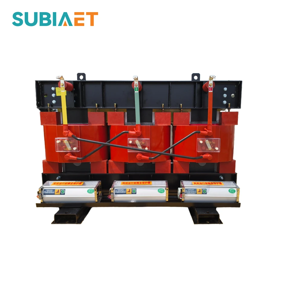
The SCBH family uses an amorphous-alloy core with a cast-resin dry-type winding arrangement. SCBH15, SCBH17 and SCBH19 are identified separately, and the electrical schedule provides both no-load and load losses for each series.
No-load loss is especially relevant when a transformer remains energized for long periods at light load. Load loss becomes more significant as operating current increases. Use the expected energization hours and load profile with the actual SCBH rating row to evaluate operating energy; a single saving percentage cannot describe every installation.
Primary-voltage options are 6, 6.3, 6.6, 10, 10.5 and 11 kV, with a 0.4 kV secondary. The SCBH technical data lists losses for reference ratings from 30 to 2500 kVA, including the separate 630 kVA impedance variants.
| Characteristic | Specification scope |
|---|---|
| Core material | Amorphous alloy |
| Construction family | Cast-resin dry-type |
| Performance series | SCBH15 / SCBH17 / SCBH19 |
| Rated capacity at 10 kV | 30–4000 kVA |
| voltaje secundario | 0.4 kV |
| Loss presentation | Separate no-load and load-loss columns for each performance series, in W |
| Impedance variants | 4% and 6% groups; two separate 630 kVA entries |
The 35 kV SCB branch brings the incoming medium-voltage supply into a dry-type indoor installation. Specify the secondary voltage and required output together; the voltage class alone does not define the winding ratio or thermal duty.
The SCB10 · 35/0.4 kV reference configuration uses 6% impedance, Dyn11 or Yyn0 connection options and off-circuit HV tapping. Its technical details contain seven rating examples, with load loss stated for F-class insulation at 120 °C.
For the project specification, keep the performance-series code, frequency, cooling duty and loss reference condition together. Ratings from a different SCB performance series or secondary-voltage arrangement should not be substituted for the selected configuration.

SCB dry-type transformers serve urban distribution, high-rise buildings, commercial centres, hospitals, hotels, tunnels, rail facilities, ports and airports. The preliminary dry-type guide also identifies data centres and indoor industrial rooms. These application names describe installation contexts; the actual room, load and protection requirements determine the transformer configuration.

Indoor building distribution brings the transformer, switchgear and ventilation into one coordinated electrical-room layout. Access and cooling space are part of the installation design.

Dedicated electrical rooms supply production equipment through the plant distribution network. Loading, ventilation and the surrounding industrial environment guide the transformer configuration.
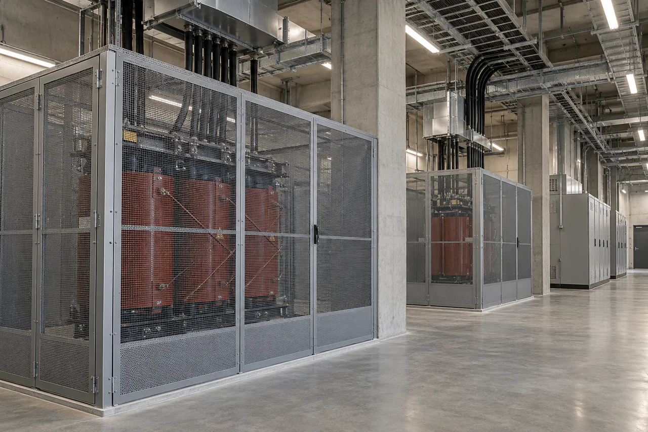
Infrastructure power rooms coordinate transformers with switchgear, cable routes and maintenance access. The electrical schedule defines the required duty for each transformer.
Entornos de aplicación ilustrativos.
The indoor layout must provide adequate cooling air, electrical clearances and access for inspection. Ambient temperature, altitude, dust and condensation conditions belong in the design review. An enclosed unit still requires a heat-removal path from the transformer, through the enclosure and out of the room.
For noise-sensitive rooms, specify the measurement requirement and the installation constraints. For loads supplied through power electronics, include the load characteristics in the enquiry. These requirements help define the design review without assuming a universal noise limit, harmonic rating or overload capability.
Indoor distribution room
Room layout, ventilation and equipment accessRevisión de diseñoCooling arrangement and enclosure position
Building or public facility
Noise requirement and local fire-safety criteriaRevisión de diseñoAcoustic and insulation-system review
Industrial load
Load profile and major connected equipmentRevisión de diseñoCapacity and thermal-duty review
Environmental exposure
Altitude, temperature, dust and condensationRevisión de diseñoInsulation, cooling and enclosure review
Replacement installation
Existing nameplate, connections and dimensionsRevisión de diseñoElectrical and mechanical compatibility
The product details contain 55 dry-type rating entries: 19 for SCB 6–10 kV, 17 for SCB 20 kV and 19 for SCBH. The schedules retain the separate model loss columns, temperature conditions and repeated capacities with different impedance values. A separate seven-row SCB10/35 reference schedule provides preliminary 35 kV loss and impedance values.
A publicly available Test Verification of Conformity identifies SCB18-2000/10-NX1 as a 2000 kVA, 50 Hz, three-phase dry-type transformer with 10 (±2 × 2.5%) / 0.4 kV rated voltage. The published copy names JIANGSU SUBIAN POWER EQUIPMENT CO., LTD. as applicant and manufacturer. Its configuration details and download are included under the SCB 6–10 kV product.
That document addresses the named specimen and Tier 2 maximum no-load and load losses. It does not state the numerical loss values, assess ongoing production or authorize use of a TÜV Rheinland conformity mark. The two-page Subian Dry-Type Transformers guide is a separate preliminary overview of applications and configuration topics.
| Document or schedule | Scope |
|---|---|
| SCB 6–10 kV electrical schedule | SCB12 / SCB14 / SCB18; 19 ratings; losses in W |
| SCB 20 kV electrical schedule | 17 ratings; B/F/H load-loss conditions in kW |
| SCBH electrical schedule | SCBH15 / SCBH17 / SCBH19; 19 ratings; losses in W |
| SCB10 · 35/0.4 kV reference schedule | Seven rating examples; F-class load loss at120 °C; published manufacturer reference |
| SCB18-2000/10-NX1 verification copy | Named 2000 kVA configuration; document dated 30 March 2026 |
| Subian Dry-Type Transformers — Selection Guide / Preliminary Edition | Two-page family introduction and configuration topics |
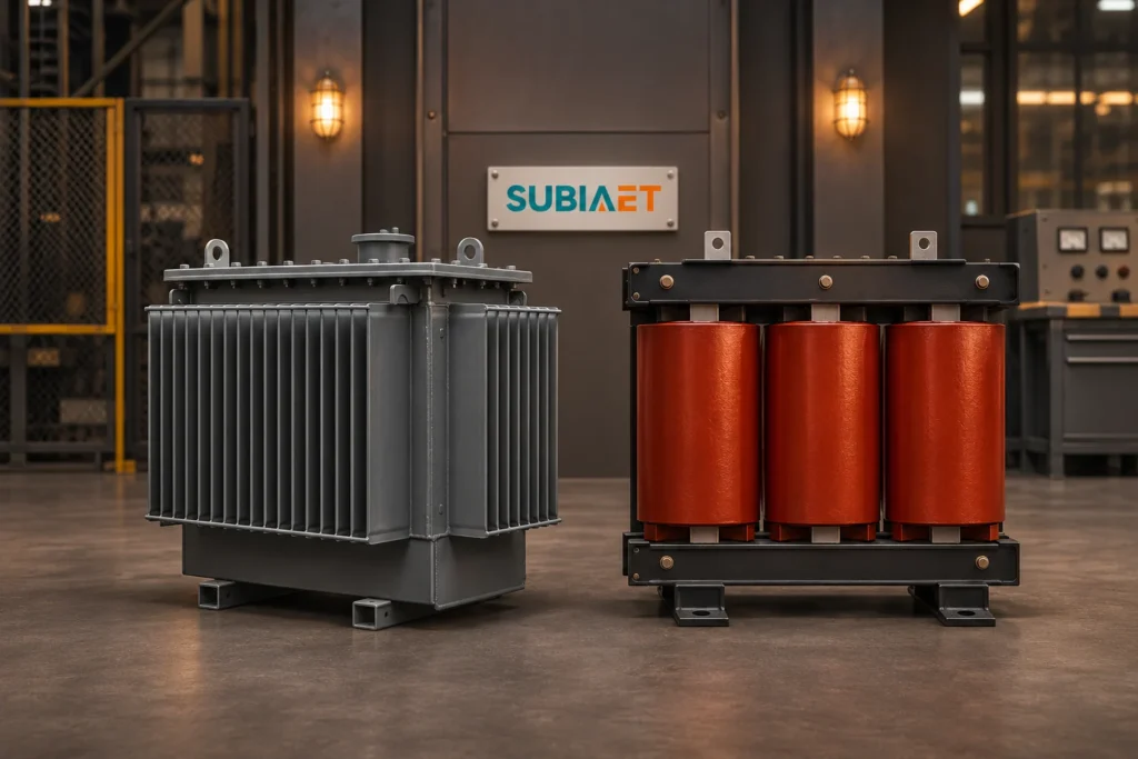
How installation conditions change the choice between oil-immersed and dry-type transformers.
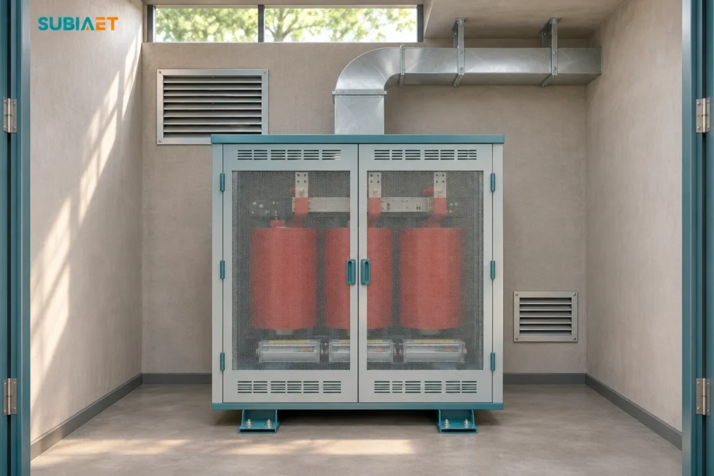
A worked example separates airflow shortfall from a standby condensation risk and sets out what to verify before handover.

A worked A/B example compares normal, transfer, bypass and recovery loads before shortlisting transformer ratings.