Solicitar presupuesto
Indique el equipo y los requisitos del proyecto. Si necesita ayuda para elegir un modelo, describa la aplicación.
¿Tiene planos o especificaciones? Envíelos a [email protected] con la referencia del proyecto.


Compare ZW32-12, ZW32-24 and ZW7-40.5 outdoor breakers by rated voltage, fault-interruption duty and installation interface. Start with the feeder study and the pole or bay drawing.
Outdoor vacuum circuit breakers
Compare voltage, current and fault-interruption duty for each complete model. Review installation and control requirements with its ratings.
ZW32-12 / OUTDOOR
12 kV outdoor feeder breaker. Specify fault duty, pole mounting and the control interface from the circuit drawing.
ZW32-24 / OUTDOOR
24 kV breaker with linked-post, operating-arm and red-mechanism configurations. Check current and breaking ratings together for the complete model.
ZW7-40.5 / OUTDOOR
40.5 kV breaker with enclosed-base, cabinet-base and open-frame configurations. Define the mounting and connection layout in the bay drawing.
Select the voltage class, then confirm the current and breaking ratings together for the complete model. Match the selected configuration to its installation drawing.
Desplácese horizontalmente para ver todas las columnas.
| Punto de revisión | ZW32-12 | ZW32-24 | ZW7-40.5 |
|---|---|---|---|
| Tensión nominal | 12 kV | 24 kV | 40.5 kV |
| Rated current options | 630 A | 630 or 1250 A | 1250, 1600 or 2000 A |
| Short-circuit breaking options | 20 kA | 20 or 25 kA | 20, 25 or 31.5 kA |
| Configurations | Grey three-pole assemblies with operating arms. | Dark linked-post, grey operating-arm and red-mechanism forms. | Enclosed cabinet-base and exposed open-frame examples. |
| Installation drawing | Check support points, pole spacing, terminal positions and operating-arm clearance. | Match the selected mechanism package, terminal arrangement and support points. | Match the selected cabinet or frame, mounting base and primary connection clearances. |
Compare insulated-pole assemblies, mechanism bases and supporting frames. Match primary connections, mounting dimensions and the control interface to the installation.
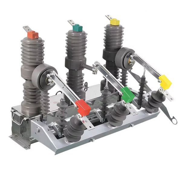
12 kV outdoor feeder breaker with three grey insulated poles, operating arms and a base assembly.
Review support brackets, terminal direction and pole spacing in the mounting drawing.
For outdoor distribution lines, pole-mounted stations and substation feeders, define the installation position and protection duty on the project single-line diagram.
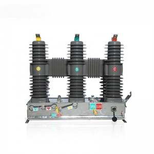
24 kV outdoor breaker with dark linked-post, grey operating-arm and red-mechanism configurations.
Specify external insulation, support height and terminal geometry for the selected mechanism and pole assembly before preparing the mounting layout.
For outdoor distribution lines and pole-mounted or substation installations, coordinate control wiring and clearances with the selected arrangement.
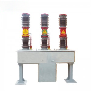
40.5 kV outdoor breaker with enclosed-base, cabinet-base and open-frame configurations.
Define the base, supports and terminal locations in the installation drawing.
For outdoor feeders and transformer bays, coordinate bay spacing, switching sequence, protection and service access in the primary design.
Start with the circuit duty, then confirm a complete ZW32 or ZW7 rating, the control interface and the installation drawings.
The single-line diagram and installation plan help define the breaker position and the required switching duty.
State the voltage class, normal current, calculated short-circuit current and switching role at the circuit position.
Compare ZW32-12, ZW32-24 and ZW7-40.5 by voltage class; verify the current and breaking ratings together on the selected model’s data sheet.
Set out trip and close commands, control supply, auxiliary signals and the protection scheme’s interface with the offered mechanism.
Check terminal geometry, supports, clearances and control wiring on the proposed drawings; list the required data sheet and test records.
The mounting drawing should locate the mechanism, primary terminals and supports, with operating and service clearances.
The agreed circuit duty and configuration drawings provide a basis for assessing the proposed breaker.
Provide the circuit duty, control scheme and installation drawing together. Identify fixed ratings and any configuration decisions still open.
A single-line diagram, protection schedule, control drawing and pole or frame layout help define the breaker package. For replacement work, include the existing nameplate and connection measurements.
Review pole, frame and replacement interfaces together with the selected breaker ratings and protection scheme.

A pole-mounted feeder installation needs the breaker, support and protection interfaces defined together.
Check conductor approach, support dimensions, terminal clearances and operating access. Specify the operating supply and relay or controller interface required by the network.

A breaker selected for an outdoor bay must fit its supporting frame, primary connections and operating access.
Review base dimensions, phase spacing, cable or bus connections, service space and site conditions. Confirm the control wiring against the selected mechanism package.

Confirm a replacement against the existing nameplate, installation measurements and control drawing before choosing the complete model.
Provide mounting centers, terminal positions, operating supply, relay inputs and auxiliary-contact requirements. Confirm current and breaking duty for the exact model designation.
Entornos de aplicación ilustrativos.
Ratings, control interfaces and installation details to confirm for the quoted breaker package.
Review the selected unit’s electrical schedule and installation drawings with the project requirements.
Start with the system voltage and required circuit duty. Confirm continuous current, breaking and withstand requirements together for the complete model, then review its insulation, installation and control interfaces.
Select continuous-current and breaking-duty ratings together for the complete breaker model. Use a combination confirmed by that model’s rated-data sheet.
State the relay or controller, sensing inputs, operating supply, commands and auxiliary-contact requirements. Define the quoted controls, supports and accessories separately from equipment supplied by others.
ZW32-24 configurations differ in pole housings and operating mechanisms. ZW7-40.5 arrangements use an enclosed base, a cabinet base or an open frame. Select the mechanism, primary connections and support layout with the required model rating.
Provide the existing nameplate, mounting dimensions, phase spacing, terminal positions, operating supply and control drawing. Replacement compatibility depends on mounting, primary terminals and control wiring as well as the electrical ratings.
Send the single-line diagram, duty and protection schedule, pole or frame layout, control requirements and quantity. Identify the supply boundary and the data sheets, drawings and test records needed for project review.
Use the same transformer feeder duty to compare a switch-fuse combination with a relay-controlled circuit breaker. See what the study and supplier…

A worked example shows why a peak current, RMS measurement and successful no-trip replay cover different parts of a protection review.

Use a fictional evidence review to check whether a transformer short-circuit test report covers the project duty and offered design.