Solicitar presupuesto
Indique el equipo y los requisitos del proyecto. Si necesita ayuda para elegir un modelo, describa la aplicación.
¿Tiene planos o especificaciones? Envíelos a [email protected] con la referencia del proyecto.

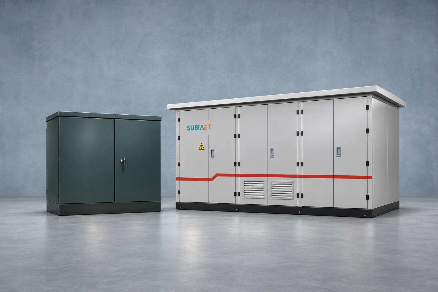
Two quotations can name a similar transformer capacity, describe the same electricity service, and still hand over two different pieces of equipment. That is the difficulty with comparing a pad-mounted transformer offer against a compact substation offer: the numbers look comparable while the equipment boundary sits in a different place.
The useful way to compare them is to follow the power path and stop at each boundary. Mark the exact equipment and terminals on the single-line before reading the totals. Where does the medium-voltage (MV) cable terminate? Which device switches load, and which device clears a fault? Where do the low-voltage (LV) conductors physically leave the supplied scope? Who provides the main incoming device, the busbar, and a protective device for each outgoing circuit?
A pad-mounted transformer is a transformer in a lockable outdoor enclosure with connection compartments. A compact substation is a coordinated assembly that may contain MV switchgear, a transformer and an LV switchboard inside one enclosure. A transformer-only quote can end at the transformer’s LV terminals. The compact station quote can end at the outgoing terminals of LV feeders or at the transformer bushing, depending on the configuration. Only a marked drawing settles which one your quote is offering.
Start with the physical object. A compartmental three-phase pad-mounted unit combines a transformer tank and its cooling surfaces with a lockable outdoor cabinet. MV cables terminate in the primary connection area, where specified switching or protection equipment may also sit. The secondary conductors land in the LV connection area. Ask the supplier to identify each cable entry and termination on the layout for the quoted arrangement. SUBIA describes its ZGS pad-mounted family as an integrated outdoor transformer with connection compartments and a load-switch/fuse arrangement.
That description already tells you how pad-mounted families differ from one another. As the SUBIA range page notes, pad-mounted design families are identified by their configured termination and switching scope. Two units with the same tank and the same capacity can differ in whether they have radial or loop-feed provisions, whether they use dead-front or live-front terminations, and whether the MV compartment contains a simple load-break switch, a switch with fuses, or something more elaborate. Those interface choices are covered in more depth in the guide to pad-mounted primary connection interfaces.
Eaton’s Cooper Power pad-mounted specification PS202002EN, sections 4.4–4.7 documents primary and secondary connections, selectable load-break switching, Bay-O-Net fusing with backup current-limiting fuses, and further choices such as an integral vacuum fault interrupter. These examples show how the transformer unit can incorporate the switching and overcurrent protection specified for the project.
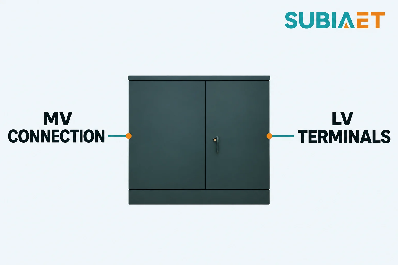
A load-break switch can switch load within its rated duty. Check fault interruption against the specified fuse combination or fault interrupter, its ratings and the protection study. Confirm visible isolation, earthing, cable-compartment access and coordination with the upstream feeder separately against the utility or site network requirements. These MV functions remain inside the transformer unit and leave the LV handoff unchanged.
The transformer’s secondary compartment is where the customer’s conductors land, typically at terminal bars or pads and a neutral terminal where provided. Some configurations include an auxiliary panel with control wiring, a fan supply or temperature monitoring. The switchboard is a separate assembly unless the quote specifically includes it.
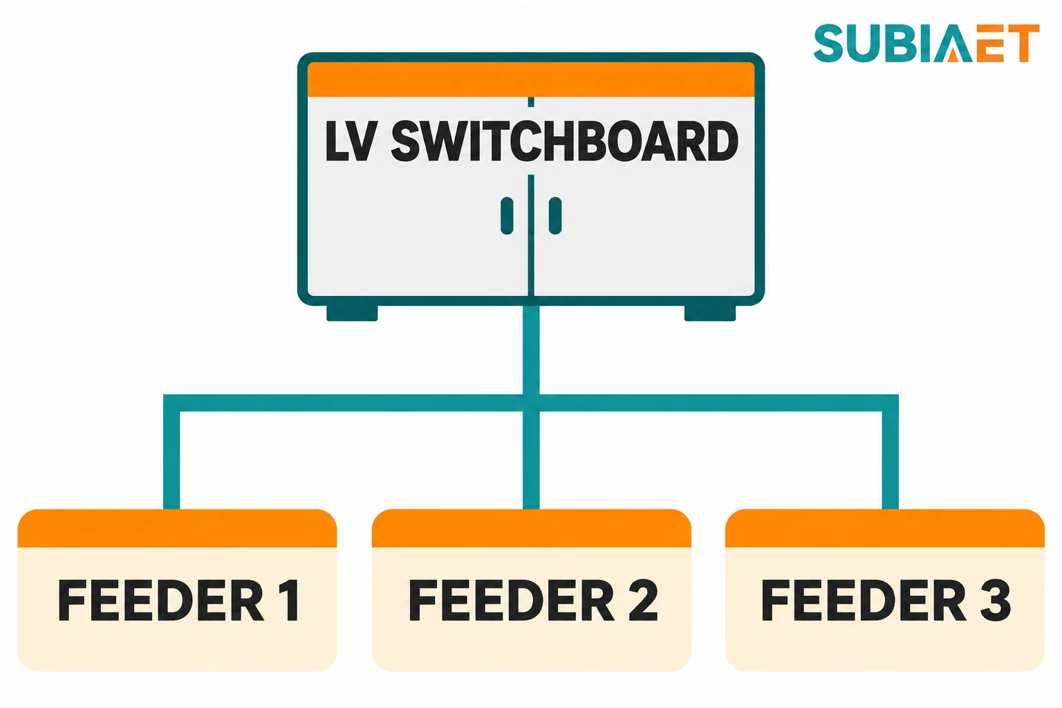
A distribution switchboard can include a main incoming device with a defined short-circuit rating, a busbar system sized for the load and a protective device selected for each outgoing circuit. Check the specified form of separation, any internal arc requirements, interlocks, cable entry and space to bend and terminate the feeders. A transformer terminal connects conductors. The switchboard distributes the supply and provides the specified circuit protection. If the switchboard is outside the quote, carry it and the conductors between the two assemblies as separate scope items.
A compact substation, sometimes called a prefabricated or secondary substation, is an enclosure containing an assembly of equipment that has been coordinated as a unit. One MV-to-LV configuration groups these functions: MV switchgear on one side, a distribution transformer in the middle, an LV switchboard on the other side, with internal connections and auxiliary circuits joining them.
ABB’s UniPack-S steel compact secondary substation is a concrete example of that arrangement. It groups MV switchgear, a transformer, an LV switchboard, the internal connections between them, and auxiliaries inside one enclosure. The feeder arrangement depends on the order. The UniPack-S catalogue also lists metering, communications and controls as options. The buyer specifies the outgoing circuits and the supplier confirms them on the single-line. Check the equipment list for metering and control functions that the project calls for.
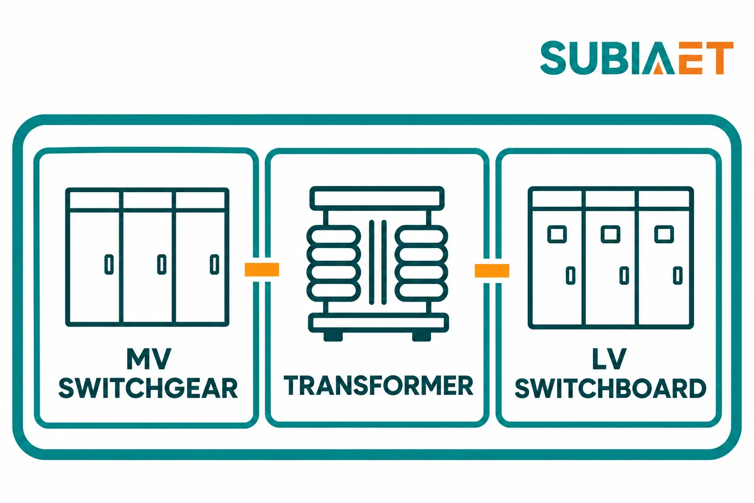
When the package includes the LV switchboard and its associated links, the equipment boundary moves in this example. Instead of ending at transformer terminals, the delivery ends at the outgoing terminals of the LV feeders, because the incoming device, the busbar, the internal links from the transformer secondary, and the branch devices are all part of the assembly. The buyer receives one coordinated piece of equipment instead of two that must be matched and wired together on site.
ABB’s solar compact secondary substation data sheet, page 1 describes one package in which the inverter equipment provides LV-side protection and the LV cable terminates at the transformer bushing. The enclosure groups the transformer and switchgear without a separately supplied LV switchboard. This is a specific solar step-up arrangement. Compare its transformer-bushing handoff with the distribution example above, where the transformer secondary connects to an LV switchboard within the quoted station. Check the incoming and outgoing equipment on the actual project before assuming either LV handoff.
The ZGS name appears in two places on SUBIA’s site. The prefabricated substation range page lists both a YB prefabricated substation and a ZGS combined substation, and illustrates a YB configuration grouping high-voltage switching, a transformer and LV distribution. ZGS also appears on the pad-mounted transformer page. So a line item reading “ZGS” could point to a pad-mounted transformer unit or to a combined station, depending on the drawing behind it. A family name and an enclosure photograph do not prove that a particular bill of materials is being offered. Ask for the arrangement drawing and the itemized equipment list before reading anything into the label.
The official IEC 62271-202:2022 publication summary describes service conditions, rated characteristics, structural requirements and methods of test for AC cable-connected prefabricated substations within its scope, including high-voltage switchgear prefabricated substations in that edition. Confirm the applicable edition for the project and request test evidence for the supplied configuration. Ask which ratings and interfaces are covered by assembly-level evidence, which have component-level records, and what remains for factory acceptance or site testing. A citation on a quotation alone leaves the configuration and test scope unverified.
Make the comparison concrete with one illustrative property. An MV-fed commercial building needs one transformer and three LV outgoing feeders, each individually protected. Use the same service and network requirements and the same three feeder duties for both quotations. Check each proposed protection scheme against the project studies and approval requirements. No specific capacity, voltage or price is needed to see the mechanism.
Quote A — pad-mounted transformer. Includes the transformer unit, the enclosure with locked MV and LV connection compartments, the specified primary switching and fusing arrangement, and the secondary terminals. It ends at the LV terminals. By others: the LV switchboard with a main incoming device, busbar and three feeder protective devices; the interconnecting conductors from the transformer secondary terminals to that board’s incoming terminals; the board enclosure and its cable space. The upstream MV cable to the transformer and the three downstream feeder cables are outside both quotes in this example, and earthing and interface responsibilities are allocated separately in the commercial documents.
Quote B — compact substation. For this example, assume the proposed MV switching and protection satisfy the project study and the network operator’s requirements. The quote includes them, the transformer, the internal links between MV equipment and transformer and between transformer and LV board, and an LV board containing the incoming device and three feeder protective devices. It ends at the outgoing feeder terminals. Still outside: the upstream MV cable, the three downstream feeder cables, the foundation or pad, the earthing electrode system and its connection to the station, and site works.
Both offers are intended for the same building and the same three feeders. The responsibility line changes which party must specify the interconnection, verify the match between the transformer secondary and the board’s incoming device, and agree the factory and site tests.
| Comparison item | Quote A: pad-mounted transformer | Quote B: compact substation |
|---|---|---|
| MV termination and switching | In the transformer’s MV compartment, as specified | In the station’s MV switchgear, as specified |
| Transformador | Included | Included |
| Links from transformer to LV board | Not included — site interconnection | Included as internal connections |
| LV main incoming device and busbar | Not included — separate LV board | Included in the LV board |
| Three individually protected feeders | Not included — separate LV board | Included as outgoing circuits |
| Equipment boundary | LV terminals of the transformer | Outgoing terminals of the three feeders |
| Enclosure | Transformer cabinet only | Single coordinated enclosure |
| Upstream MV cable | External | External |
| Downstream feeder cables | External | External |
| Foundation, earthing network, site works | External | External |
The compact substation quote covers the specified internal work. Trenches, cables, foundations and external earthing remain site work in this example. The pad-mounted transformer quote covers a complete transformer unit at its own boundary. Whether that scope is sufficient depends on what the project already has on the LV side and who will supply the rest.
Start with the existing equipment. A transformer-only scope can fit when the project already has a compatible, approved LV distribution board with documented short-circuit ratings and protection settings. The transformer quote fits if the MV protection and coordination requirements are satisfied inside the unit or upstream of it, and if the interconnection between the transformer secondary and the existing board is properly designed, rated and installed by someone with clear responsibility for it.
When the buyer wants one factory-assembled equipment scope, an integrated package can place the internal links and the transformer-to-LV-board interface with one supplier. State which equipment sits inside the enclosure, the ratings and protection duties it must meet, and the evidence required for the coordinated assembly and its components.
Compare the two options on five dimensions before choosing. The physical interface: footprint, cable entry direction, clearance for cable bending, access for replacing a device, and future extension or spare ways. The electrical interface: short-circuit withstand, discrimination between the LV incoming device and the feeder devices, and coordination with the upstream MV protection. Network approval: whether the utility requires specific visible isolation, earthing facilities, or a particular switching arrangement at the MV termination. Service access: who can open which compartment, and what isolation is needed before a device can be replaced. Test scope and total installed system cost: which factory and site tests each supplier includes, the interfaces left to the installer, and the labour for site interconnection.
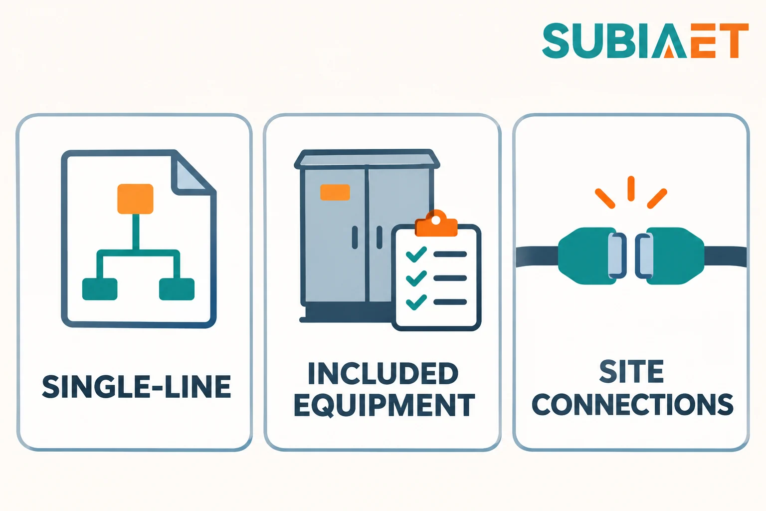
Before accepting either scope, ask for three things and read them against each other. First, a single-line diagram that shows exactly where the supplier’s responsibility stops. Second, an itemized equipment list that names every assembly, device and internal link included, and explicitly lists what is excluded. Third, a list of site connections stating which party provides and terminates each cable and which party owns the earthing connection.
If the project is a renewable connection rather than a conventional load, the questions shift slightly because the LV protection may already sit in the generating equipment. The SUBIA guide to compact substations for renewable energy connections covers the civil and SCADA interfaces and the factory acceptance test scope to define before an RFQ. For a conventional arrangement, the pad-mounted transformer range and the prefabricated substation range show the two equipment forms, and the explanations of pad-mounted transformer parts and layout y prefabricated substation components and power flow show how each is put together.
A practical next step: take the two quotations you are actually holding, draw one single-line diagram covering both, and mark where each quote stops. If the two boundary lines fall in different places, the prices are not comparable yet — and the missing scope may include an LV switchboard, the interconnecting conductors or the labour to install and test them.
No. Capacity describes the transformer, not the scope around it. A pad-mounted transformer at a given capacity and a compact substation containing a transformer of the same capacity can differ by an entire LV switchboard, the internal links between the transformer and that board, and the enclosure that houses both. Two offers are only comparable once the single-line diagram marks the same supply boundary on each, and both cover the outgoing circuits specified for the project. If the vendor handoffs differ, add the price of separately supplied equipment, links and site work to reach the same installed scope.
The label alone cannot tell you. On SUBIA’s site, ZGS appears both as a pad-mounted transformer family with connection compartments and a load-switch/fuse arrangement, and as a combined substation name listed alongside the YB prefabricated station, where the illustrated YB arrangement groups high-voltage switching, a transformer and LV distribution. The only reliable way to tell them apart is the arrangement drawing and the itemized bill of materials behind the quotation. Ask for both, and check whether an LV switchboard and internal links appear in the list.
Check the quoted LV assembly. A pad-mounted unit can have specified primary load-break switching and separate fault protection using fuses or an integral vacuum fault interrupter. Primary equipment can handle the specified MV duties while the LV connection still stops at terminal bars. If the project needs individually protected LV outgoing circuits, look for the devices, distribution assembly and links on the quotation and single-line.
Some configurations supply a separate LV switchboard. Others end at a transformer connection. ABB’s solar compact secondary substation data sheet describes a package in which LV-side protection sits in the inverter equipment and the LV cable terminates at the transformer bushing, with the enclosure grouping the transformer and the switchgear. The MV-to-LV configuration in the UniPack-S catalogue does include an LV switchboard, but it also notes that the feeder arrangement depends on the order. Check the quoted drawing and equipment list to see which arrangement is supplied.
Send the load schedule and the single-line diagram with your intended supply boundary marked, state how many outgoing feeders are required and that each needs its own protective device, and state what already exists — particularly whether an approved LV board is in place. State the network operator’s requirements for isolation and earthing at the MV termination, and ask for the itemized equipment list with exclusions named, plus the list of site connections and who owns each one. With that input, both suppliers can price the same equipment handoff and identify work that must be quoted separately.
