Запросить коммерческое предложение
Укажите оборудование и требования к проекту. Если вам нужна помощь в выборе модели, опишите условия применения.
Есть чертежи или спецификации? Отправьте их на [email protected] и укажите номер или название проекта.

For medium-voltage distribution
and industrial substations.
Sealed distribution designs and a 35 kV substation family, with electrical configurations matched to the network.
30–4000 kVA at 10 kV · 0.4 kV secondary
Fully sealed three-phase distribution transformers.
30–4000 kVA · 20/0.4 kV
Fully sealed distribution transformers with ONAN cooling.
Substation and industrial duty
ONAN-cooled oil-immersed construction for distribution substations and industrial power transformation.
| Family | Primary voltage | Secondary voltage | Rated-capacity coverage | Rating detail |
|---|---|---|---|---|
| S series 6–10 kV | 6 / 6.3 / 10 / 10.5 kV options | 0.4 kV | 30–4000 kVA at 10 kV | 19 reference ratings up to 2500 kVA with S13-M, S20-M and S22-M loss data |
| S series 20 kV | 20 kV | 0.4 kV | 30–4000 kVA | 19 reference ratings up to 2500 kVA with loss, no-load current and impedance data |
| S series 35 kV | 35 kV class | Specified by project | Specified by project | ONAN cooling; substation and industrial applications |
Capacity, impedance and loss values belong to the same rating entry. Primary-voltage options identify alternative winding designs; they do not describe switching between system voltage classes in service.
The model designation separates the number of phases, design series, tank arrangement, rated capacity and high-voltage class. S identifies a three-phase transformer. For the sealed distribution designs, M identifies the fully sealed tank construction.
S11, S13, S20 and S22 appear in the distribution-family descriptions. The 6–10 kV rating table gives separate no-load and load-loss values for S13-M, S20-M and S22-M. Use the complete rating row and the purchase specification when selecting a loss level; the design code alone does not define the secondary voltage, vector group or every accessory.
| Field | Meaning | How it is used |
|---|---|---|
| S | Three-phase | Identifies the phase arrangement |
| 11 / 13 / 20 / 22 | Design series | Identifies the series; use the corresponding electrical schedule |
| M | Fully sealed | Identifies the sealed distribution-tank arrangement |
| Capacity field | Rated capacity in kVA | Defines the rated apparent power |
| Voltage field after / | High-voltage class in kV | Identifies the primary-voltage class |
The 6–10 kV and 20 kV designs use high-permeability, grain-oriented cold-rolled silicon-steel laminations. Fully oblique joints form the stacked core; stepped core limbs approach a circular cross-section, while the yoke and limbs use equal cross-sectional areas. The core limbs and yoke provide the magnetic path.
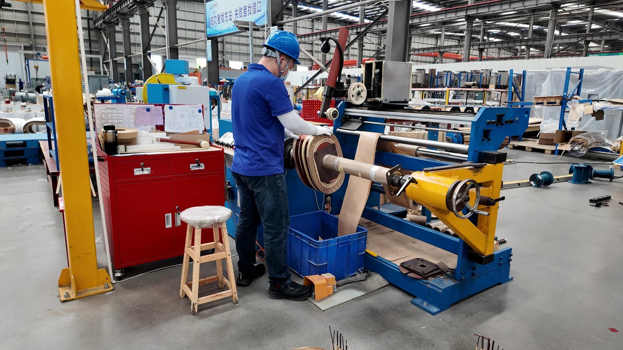
Concentric high- and low-voltage windings incorporate oil passages and compression binding. The oil passages carry heat from the winding region into the surrounding insulating oil. Compression binding maintains winding position within the active assembly. These channels provide circulation paths for heat transfer.
High-voltage tapping leads connect the winding to the cover-mounted tap switch, keeping voltage adjustment within the specified winding design. The selected winding tap connects to the supply.
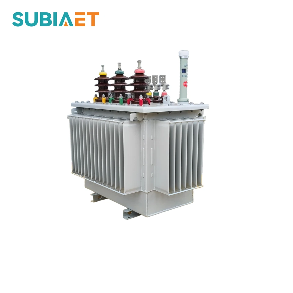
The fully sealed designs use corrugated tank walls.
Inspection still applies. Follow the operating instructions and installation conditions.
Oil natural · Air natural
20 kV / 35 kVHeat moves through circulating oil and then from the tank or radiator surfaces to ambient air. Tank arrangement, surface treatment and available cooling space form part of the installation specification.
| Item & configuration | Installation or quotation requirement |
|---|---|
| 6–10 kV and 20 kV tankFully sealed corrugated-wall construction | Allow space for cooling surfaces and access to fittings |
| 20 kV coolingONAN | Keep the air path around the tank unobstructed |
| 35 kV coolingONAN | Coordinate tank and radiator arrangement with the substation layout |
| Surface protectionCoating selected for the installation environment | Identify humidity, coastal exposure and corrosive contamination at quotation stage |
20 kV public configuration.
Versions discussed in the wider distribution-family descriptions.
The selected vector group must agree with the network neutral arrangement and the other equipment connected to the busbar.
Coordinate these four items as a system:
Local indications and signals for the station protection scheme.
Releases abnormal internal pressure
Described distribution design.
Provides alarm and trip contacts
Coordinate with the transformer design.
Indicates oil temperature
Indicates oil level
Select to suit the tank arrangement.
The 35 kV family lists oil-level indication, thermometers, pressure relief and gas-relay protection as configuration items.
The protection arrangement must match the tank construction and the project protection design.
Local gauges, alarm contacts and trip contacts perform different functions.
The station control drawing should show how each specified device is used.
Oil thermometer: define the pocket location and any signal contacts in the accessory schedule.
No-load loss contributes whenever the transformer is energized.
Load loss changes with operating current.
The project loading profile determines how each loss component affects energy consumption.
A loss figure therefore needs its voltage, frequency and test conditions before it can be used in a lifecycle-cost calculation.
For 10 kV ratings above 2500 kVA, request the no-load loss, load loss and short-circuit impedance for the proposed design.
No-load loss contributes whenever the transformer is energized.
Load loss changes with operating current.
The project loading profile determines how each loss component affects energy consumption.
A loss figure therefore needs its voltage, frequency and test conditions before it can be used in a lifecycle-cost calculation.
For the 30–500 kVA entries, this schedule does not state a single load-loss value. The required value and test condition must be agreed in the project electrical schedule.
For 20 kV ratings above 2500 kVA, request the no-load loss, load loss and short-circuit impedance for the proposed design.

Its role is voltage transformation within a medium-voltage supply system. The voltage ratio, insulation requirements, capacity and protection arrangement are defined together with the substation single-line diagram.
The described construction combines a grain-oriented silicon-steel core with oblique stacked joints, a rigid clamping frame and axially compressed windings.
Core-clamping frame; axial winding compression and positioning.
ONAN cooling transfers heat through the oil circuit and the external cooling surfaces.
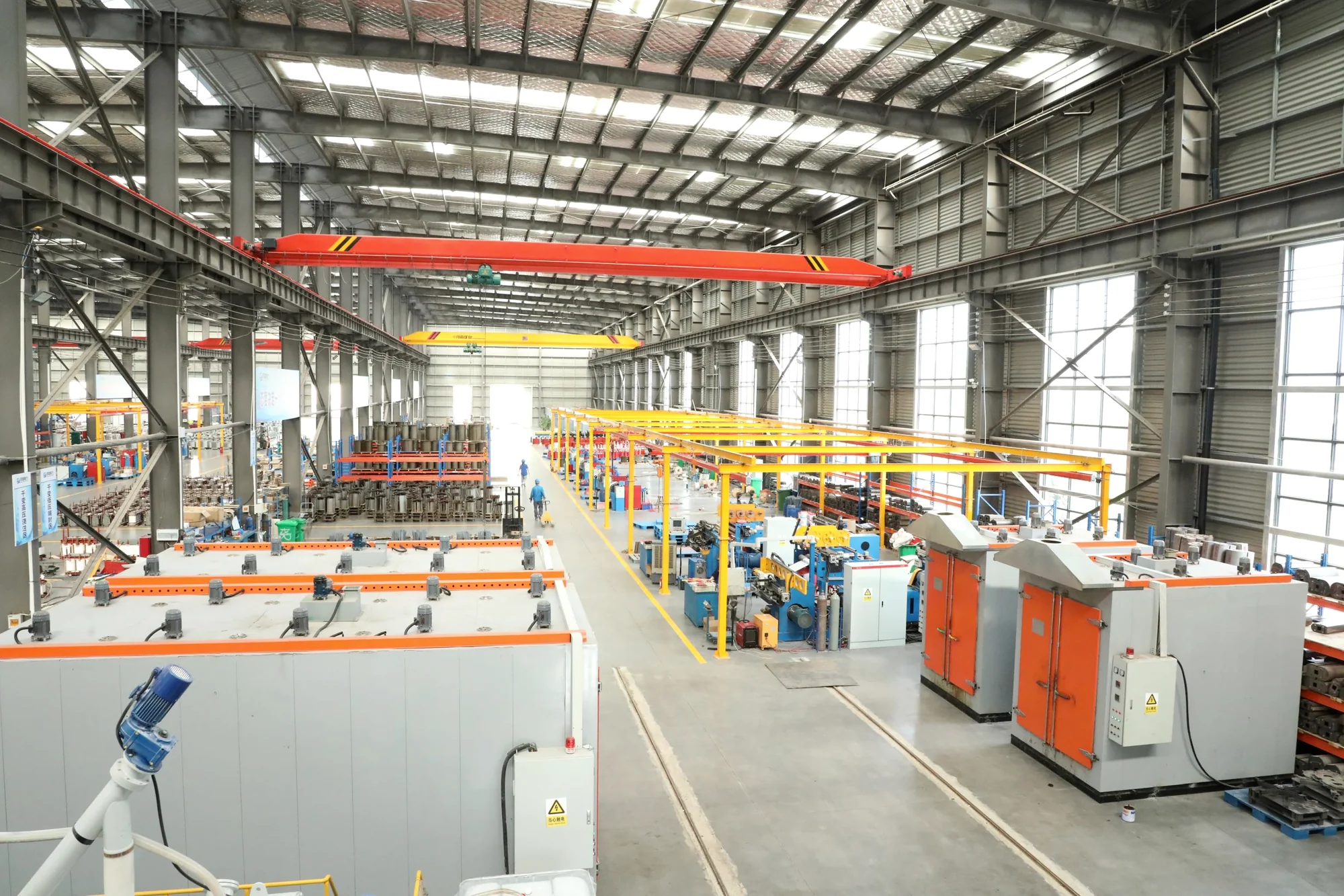
The 35 kV oil-immersed family serves distribution substations, industrial parks, mines and factories.
Pressure relief, oil-level indication, temperature indication and gas-relay protection are coordinated with the chosen tank design.
Indication devices: oil-level gauge and thermometer.
The installation drawing establishes the bushing positions, terminal clearances, cooling layout, foundation interface and service access.
These interfaces are specific to the selected transformer configuration; they should be checked alongside the electrical schedule when planning the substation.
Oil-immersed transformers support utility networks and industrial facilities. Each installation combines a different load profile, operating environment and equipment layout.

Supply utility distribution networks with configurations reviewed against continuous load, peak demand and expected growth.

Serve textile, light-industry and other manufacturing facilities. Load profiles and available installation space guide the electrical rating and equipment arrangement.

For metallurgy, petroleum and chemical facilities, review process loading alongside contamination exposure, protection interfaces and maintenance access.
Illustrative application environments.
Go further into project selection, quotation comparisons and technical checks.

A buyer’s guide to checking transformer routine test reports, with an illustrative load-loss review and a pre-shipment closure checklist.
Read guide
See how no-load and load losses change the evaluated cost of two hypothetical transformer quotations under different load profiles.
Read guide
A selection workflow from plant duty and site constraints to electrical compatibility and comparable transformer quotations.
Read guide