Phone:
(701)814-6992
Physical address:
6296 Donnelly Plaza
Ratkeville, Bahamas.

Phone:
(701)814-6992
Physical address:
6296 Donnelly Plaza
Ratkeville, Bahamas.
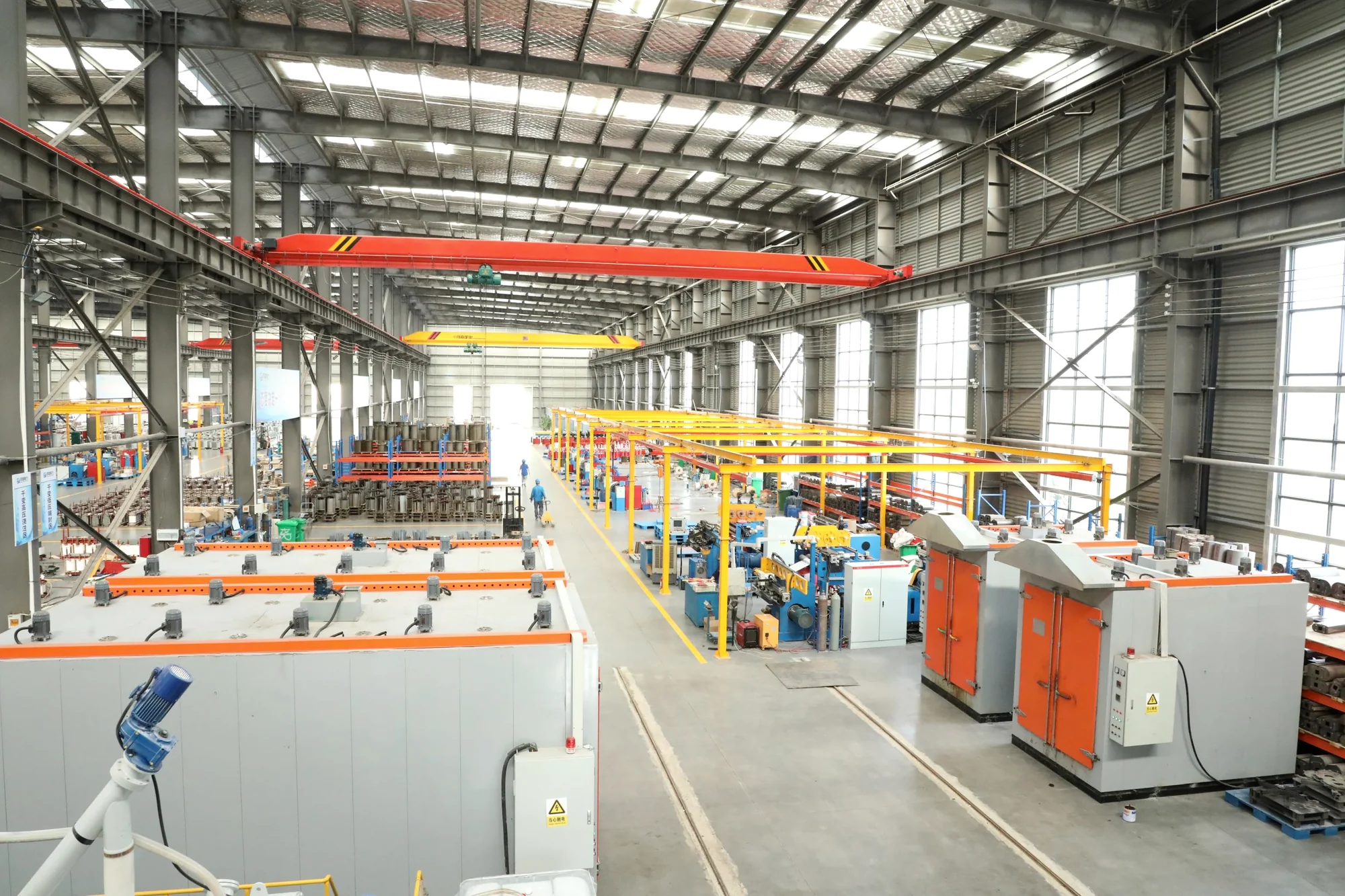
YB and ZGS station arrangements bring medium-voltage switching, a transformer and low-voltage distribution into a project-defined package. Compare their equipment grouping and site interfaces before setting the final configuration.
Prefabricated substations
Compare the sectionalized YB arrangement with the compact ZGS combined assembly. Open a product to review its configuration information and the project details needed for selection.
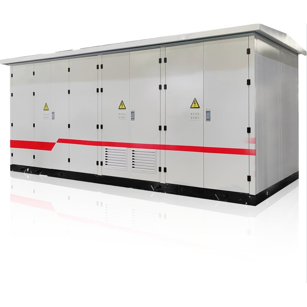
Factory-assembled enclosure grouping high-voltage switchgear, a distribution transformer and low-voltage distribution. Review compartment access and circuit interfaces with the station drawing.
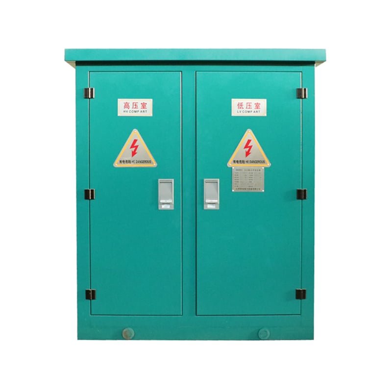
Compact assembly combining the transformer with high- and low-voltage equipment. Confirm the switching, protection and service interfaces within the available footprint.
The YB series groups high-voltage switchgear, a distribution transformer and low-voltage distribution in a prefabricated enclosure. YB-12 uses a factory-assembled station arrangement; equipment grouping, cable entries and access are set by the project scheme.
YB enclosure options include closed panels, access doors and ventilated designs.
YB enclosure configurations
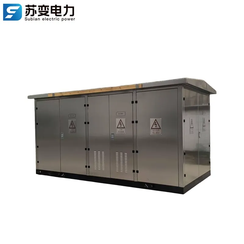
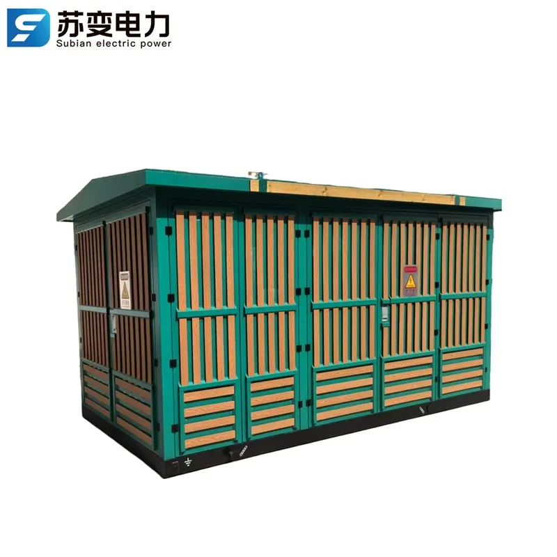
High-voltage switchgear compartments and operating interfaces.
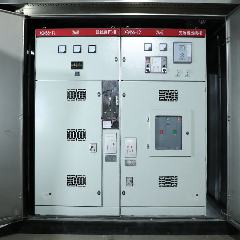
The series range and the 10/0.4 kV reference configuration are separate. Confirm the voltage pair, transformer capacity and enclosure protection for the selected unit.
Scroll sideways to see all values.
| Item | Value |
|---|---|
| Station assembly | High-voltage switchgear, distribution transformer and low-voltage distribution |
| Series HV voltages | 6 / 10 / 12 / 24 / 35 kV |
| Series LV voltages | 0.4 / 0.69 kV |
| Series overview capacity | 50–2500 kVA |
| 10/0.4 kV reference configuration | 50–1600 kVA, 50 Hz |
| Enclosure protection | Specify for the selected arrangement and site conditions |
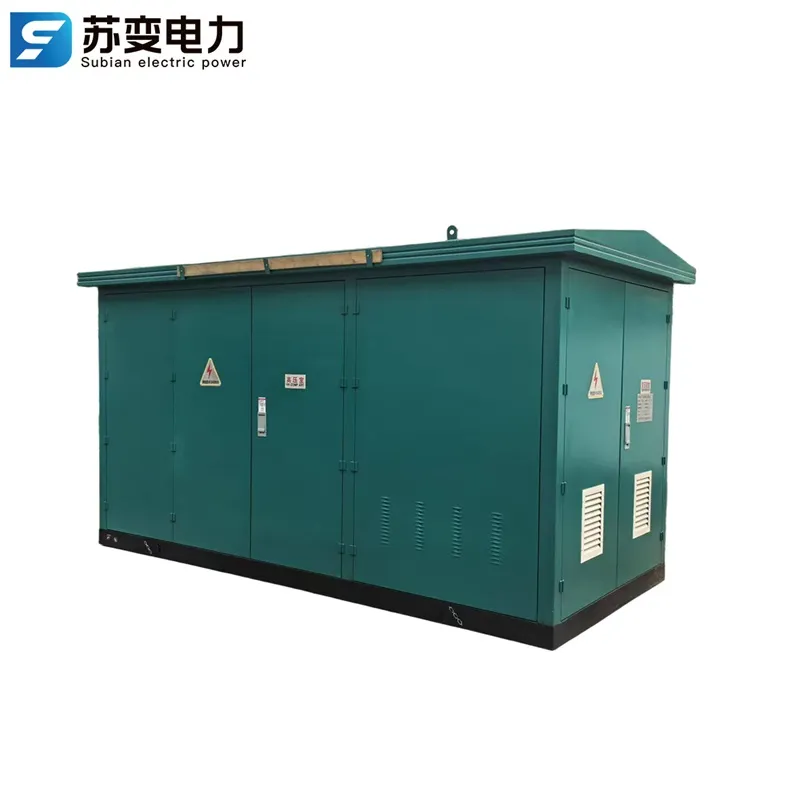
The ZGS series places the transformer and high- and low-voltage apparatus in a compact combined station. Its footprint and access faces need to be checked against the circuit schedule and site layout.
ZGS front access and rear enclosure panels.
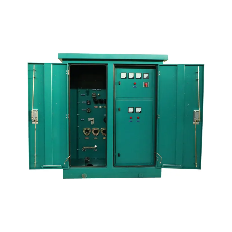
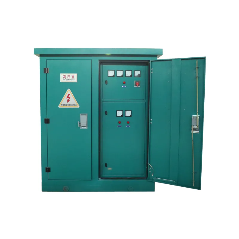
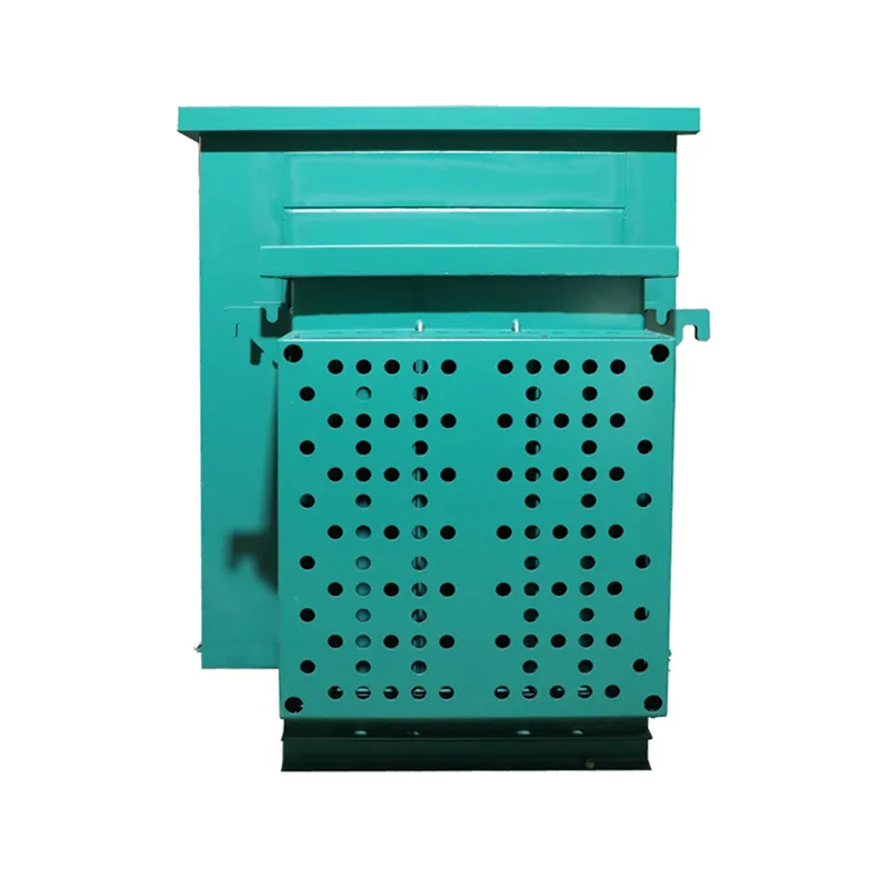
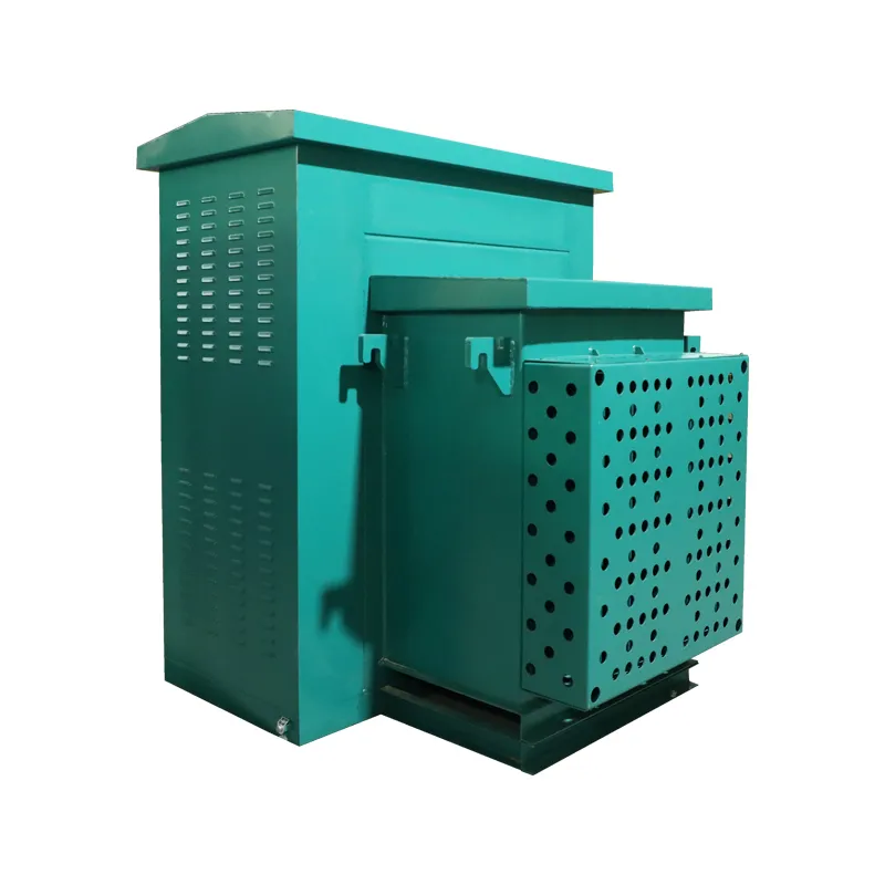
Match transformer duty, cable terminations and maintenance access to the ZGS arrangement.
Scroll sideways to see all values.
| Item | Value |
|---|---|
| HV/LV rated voltage | 10/0.4 kV |
| HV maximum operating voltage | 12 kV |
| Capacity range | 50–1600 kVA |
| Rated frequency | 50 Hz |
| Enclosure protection | IP43 |
Station construction
Both series combine medium-voltage, transformer and low-voltage duties. Compare their physical grouping, access and site interfaces before specifying the station.
A factory-assembled enclosure for high-voltage switchgear, a distribution transformer and low-voltage distribution.
A compact combined station that integrates the transformer with high- and low-voltage apparatus.
Specification process
Start with the circuit scheme and station boundary, then review construction, site drawings and required documents.
List incoming and outgoing circuits, switching, protection and metering duties on the single-line diagram.
Compare the YB enclosure and ZGS combined arrangement against access, footprint and circuit needs.
Match transformer duty, MV/LV equipment, cables, earthing, foundation and service access to the layout.
Review the data sheet, general arrangement, required test records and division of factory and site work.
A defined electrical scheme and supply boundary make the proposed station easier to assess.
Arrangement comparison
Both series need a defined electrical scope. Compare their equipment grouping and access against the site drawing; confirm ratings for the chosen configuration.
| Review point | YB prefabricated station | ZGS combined station |
|---|---|---|
| Equipment grouping | High-voltage switchgear, transformer and low-voltage distribution are grouped in a prefabricated enclosure. | Transformer and HV/LV apparatus form a more compact combined assembly. |
| Electrical scheme | Define MV and LV functional units from the incoming and outgoing circuit schedule. | Check that the required switching, protection and outgoing circuits fit the combined layout. |
| Service access | Review access to each equipment area, doors and required working clearances. | Review access faces, isolation procedure and maintenance space around the compact unit. |
| Site interface | Coordinate enclosure position, cable entries, foundation and ventilation. | Coordinate footprint, cable terminations, lifting and foundation. |
| Configuration drawings | Review equipment schedule, compartment access and cable positions on the enclosure drawing. | Review the combined assembly, terminations and maintenance faces on its general arrangement. |
Quotation information
Describe the electrical scheme, equipment scope and site conditions together. Mark values already fixed by the project and any decisions still open.
A single-line diagram, load schedule, equipment list and site plan help define the station. Include the latest available drawings, even if some details are pending.
Application context
Review the electrical and site interfaces that change between local networks, industrial loads and remote supply points.
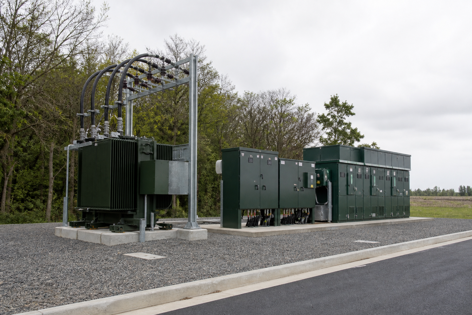
A prefabricated station can group MV supply, transformer and LV feeders for a local distribution point.
Confirm feeder number, network voltage, load growth, public-site access and the enclosure footprint before choosing the station form.
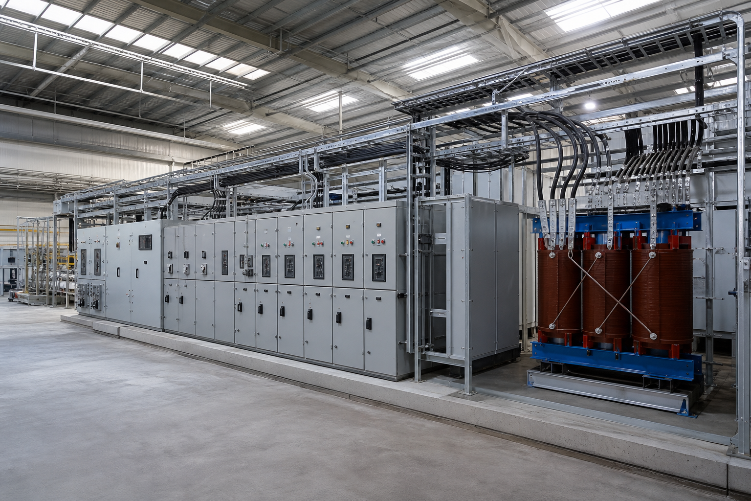
The station must fit the incoming supply and outgoing process or building loads.
Use the protection scheme and load schedule to set equipment functions; then review cable routes, ventilation and maintenance access.
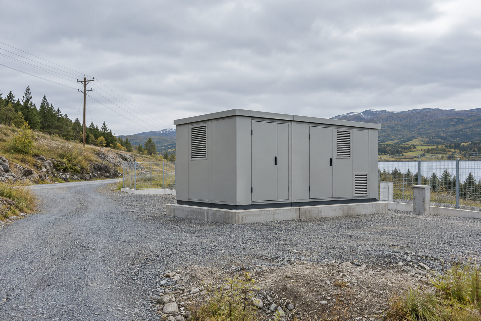
A site with limited infrastructure still needs a complete electrical and installation boundary.
Check transport, lifting, foundation, earthing and outdoor exposure alongside the circuit and load requirements.
Specification questions
Answers to common questions about station scope, YB and ZGS selection, drawings and site work.
Define the MV switching and protection, transformer, LV distribution and enclosure together. The single-line diagram and equipment schedule should show cable, earthing and site interfaces as well as the supply boundary.
The YB series groups high-voltage switchgear, a transformer and low-voltage distribution in a prefabricated enclosure. The ZGS series uses a tighter combined assembly. Compare the required circuits, access, terminations and footprint on the proposed drawings.
No. Voltage pair, circuit count, switching, protection, metering and enclosure conditions determine the complete station. Check the transformer duty within that electrical scheme.
The YB series range and the 10/0.4 kV reference configuration have different capacity limits. Confirm the voltage pair, capacity and enclosure protection in the data sheet for the unit proposed to your project.
Share the single-line diagram, load schedule, equipment list and site layout. State any required general arrangement, test records and project standards, and mark which values are still open.
That depends on the supply boundary. Assign foundation, lifting, MV/LV cables, earthing and commissioning responsibilities in the project documents; factory assembly does not remove every site task.