Phone:
(701)814-6992
Physical address:
6296 Donnelly Plaza
Ratkeville, Bahamas.

Phone:
(701)814-6992
Physical address:
6296 Donnelly Plaza
Ratkeville, Bahamas.
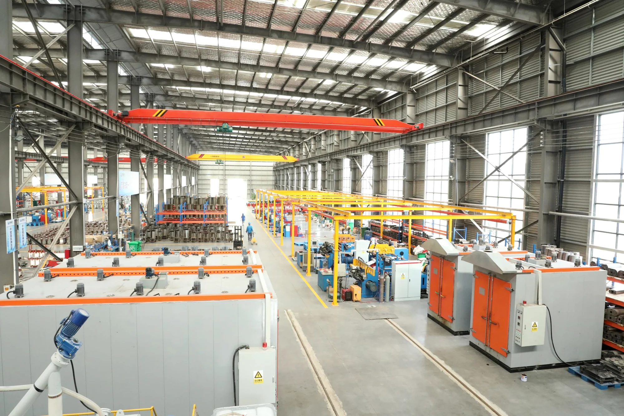
Cast-resin dry-type and oil-immersed transformers for building distribution, industrial facilities and substations. Explore the product forms and installation details that shape selection.
Power transformers
Explore dry-type and oil-immersed transformers for distribution and substation projects. Select a product to review its specifications, technical parameters and capacity data.
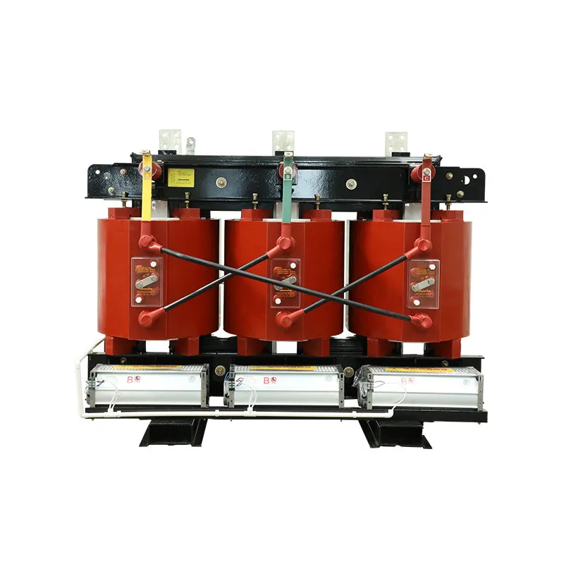
Cast-resin unit for indoor building distribution, with room ventilation, enclosure and HV/LV terminations to plan.
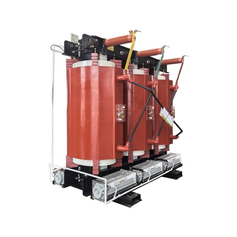
Cast-resin unit for infrastructure distribution; coordinate electrical duty, insulation and indoor interfaces with the network scheme.
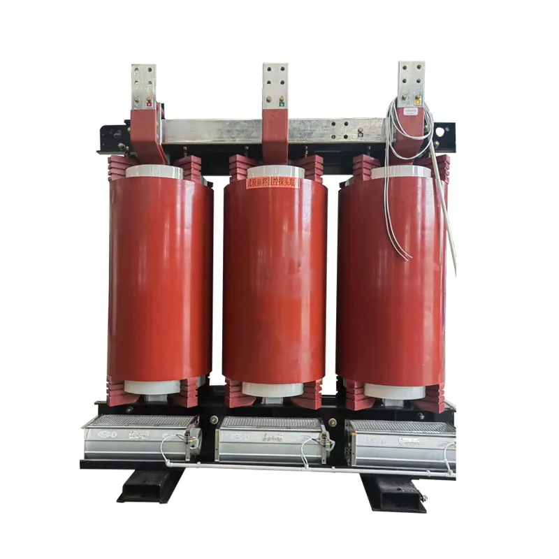
SCB epoxy-resin dry-type construction for indoor infrastructure distribution.
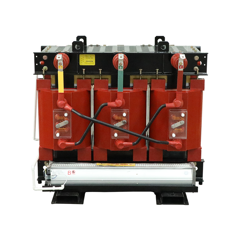
Amorphous-alloy core in a dry-type form; compare the project loss schedule and installation requirements.
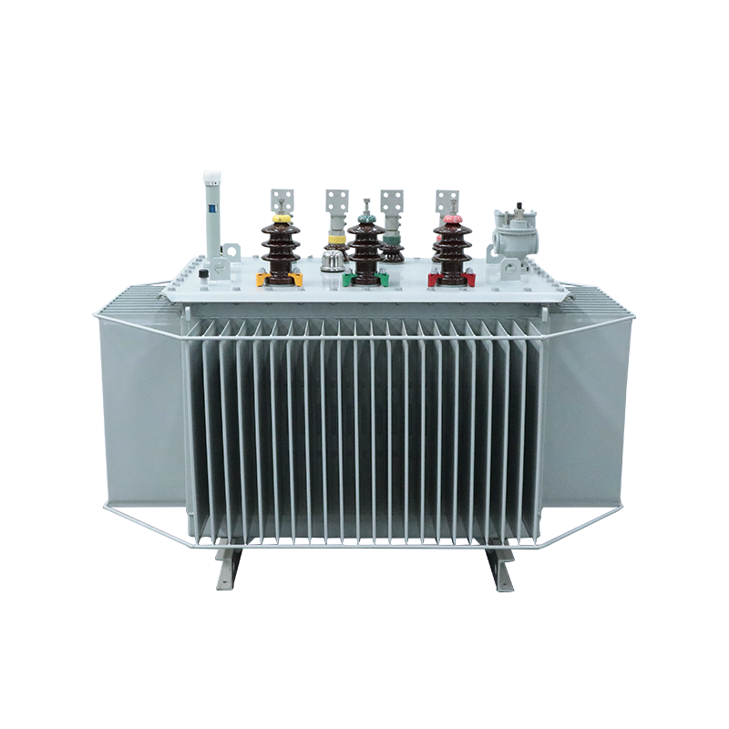
Oil-filled distribution unit for local networks; plan tank position, bushings, tap arrangement and site access.
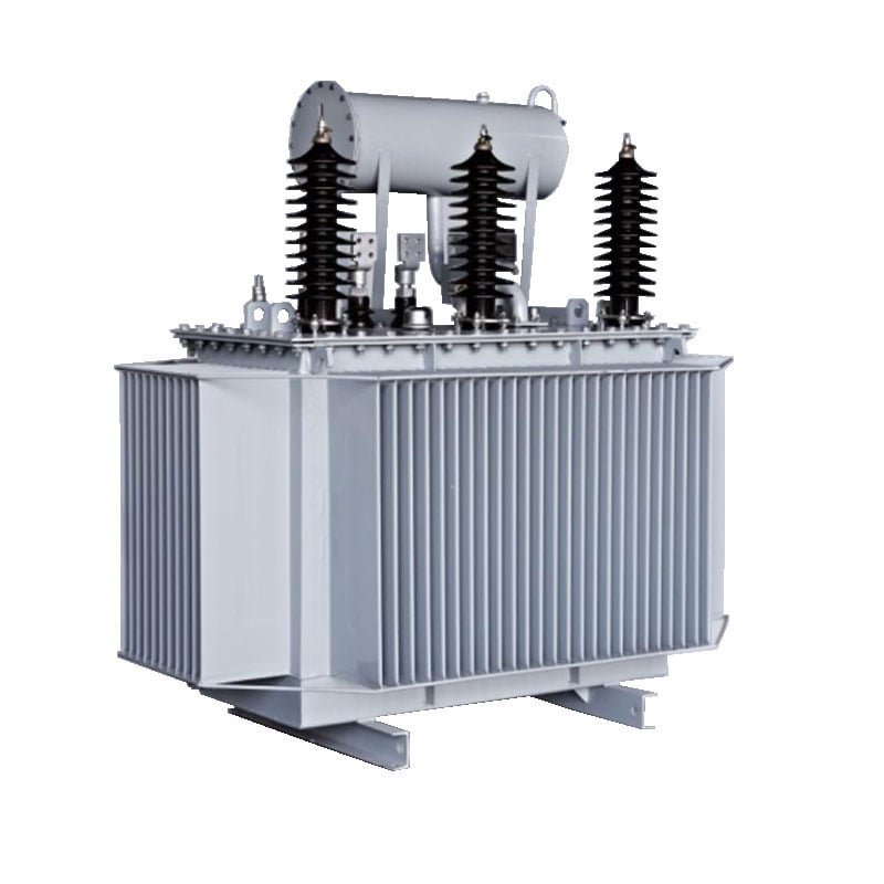
Oil-filled unit for industrial and utility distribution; coordinate cooling, terminals and service access.
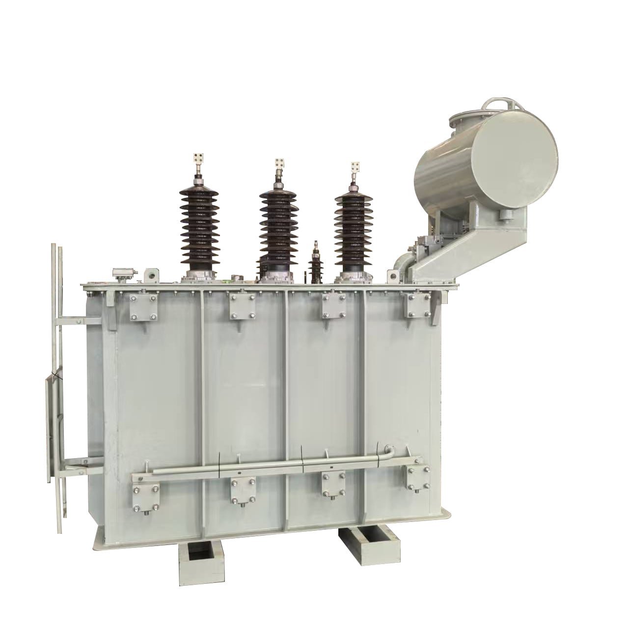
Oil-filled power transformer for substation layouts; plan bushings, protection interfaces and foundation.
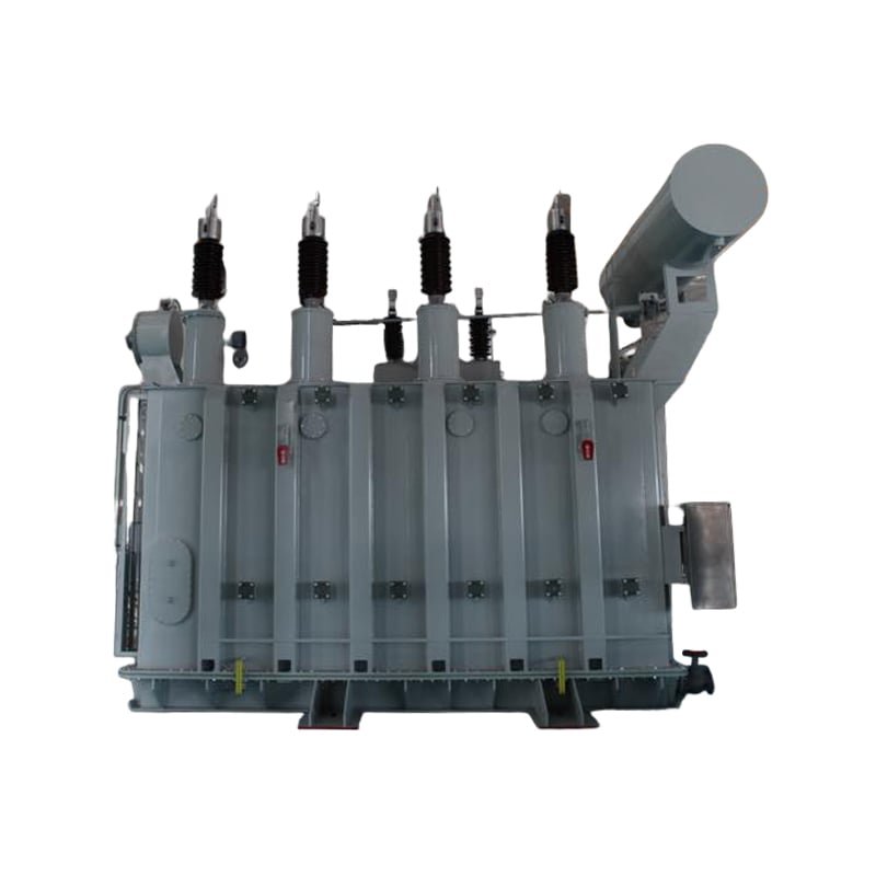
Oil-immersed construction for industrial and regional distribution connections.
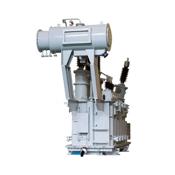
High-voltage oil-immersed construction for regional grid applications.
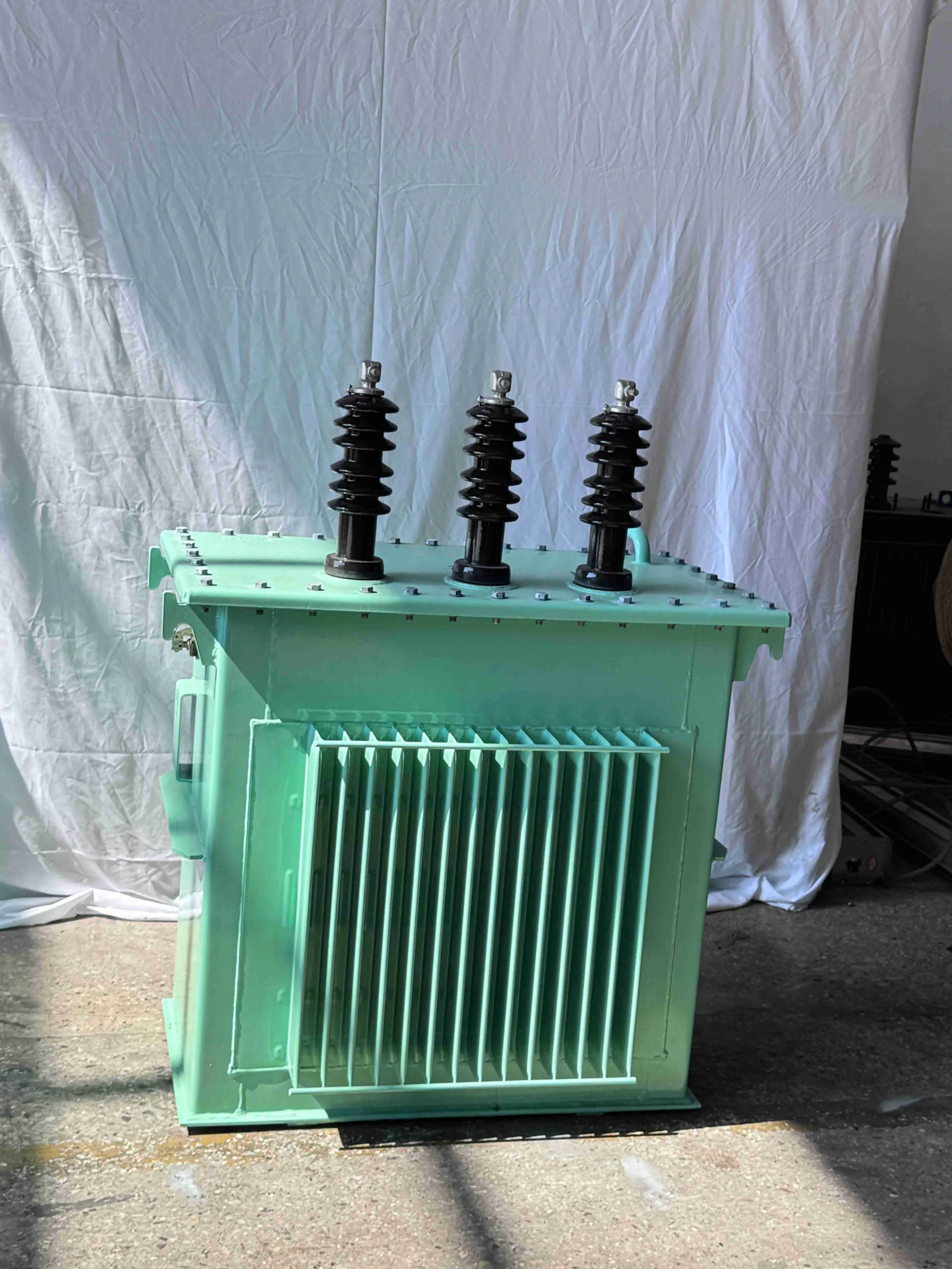
Three-phase pole-mounted distribution form for overhead network installations.
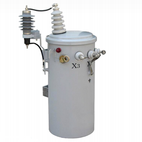
Single-phase pole-mounted oil-immersed form for distribution networks.
| Item | Value |
|---|
| Parameter | Value |
|---|
Select the voltage pair, capacity, impedance and loss values for the required model.
| Item | Details |
|---|
A single-line diagram, load schedule or existing nameplate helps define the electrical duty. Add a site drawing if space or access is limited.
Transformer construction
Cast-resin dry-type equipment uses air cooling, while oil-immersed equipment places the active part in an oil-filled tank. Compare their installation and service interfaces before specifying a unit.
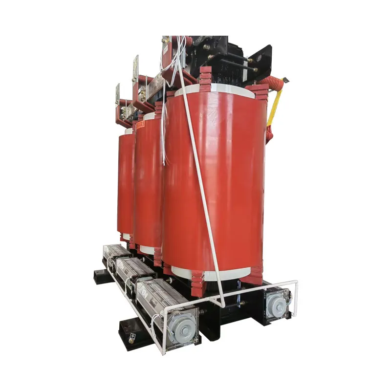
For indoor distribution rooms where ventilation and service access can be planned around the transformer.
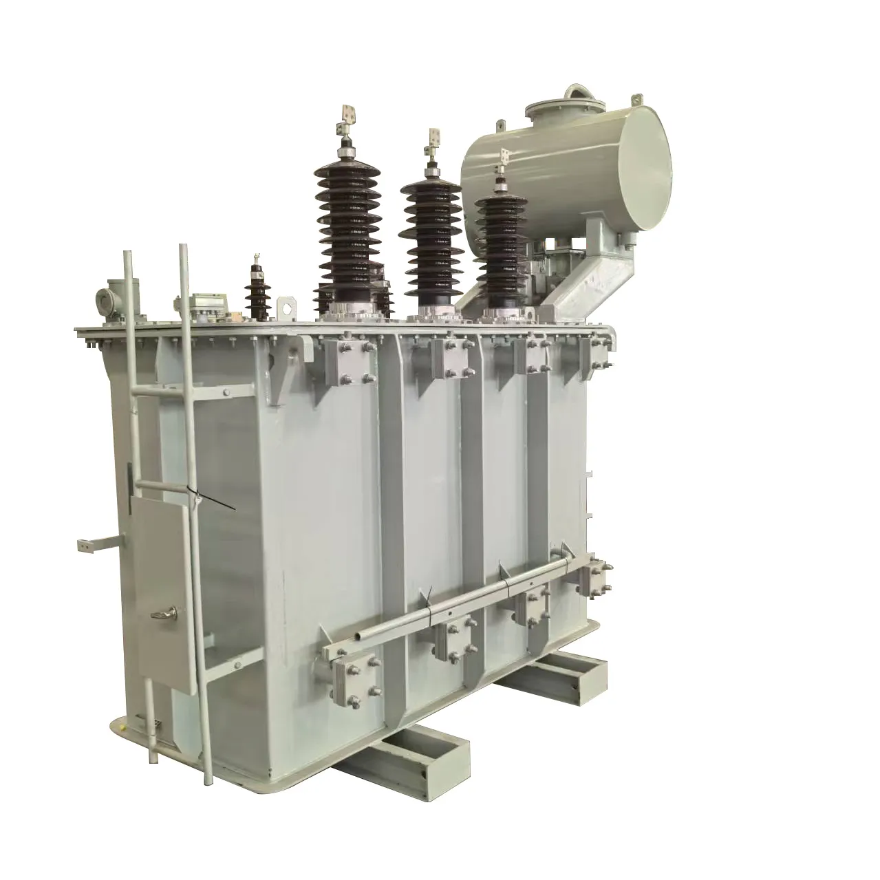
For substation, utility or industrial distribution duties where the tank and network connections fit the site layout.
Specification process
Start with the electrical duty and site requirements, then compare construction, drawings and required documents.
Provide the voltage ratio, capacity basis and network connection. Existing equipment details help with replacement projects.
Compare dry-type and oil-immersed arrangements against site conditions, access, ventilation and protection.
Review outline and connection drawings for installation space, cable or busbar entry and maintenance clearances.
List the data sheet, applicable test records and compliance documents needed for procurement.
A complete brief makes the proposed unit easier to assess against the project.
Construction comparison
Construction affects heat management, connection layout and the space needed on site.
| Review point | Dry-type transformer | Oil-immersed transformer |
|---|---|---|
| Insulation system | Cast-resin windings provide dry insulation; assess enclosure and site conditions. | The active part sits in insulating oil inside a tank; specify the oil and tank arrangement for the project. |
| Heat rejection | Plan an air path and room or enclosure ventilation; confirm whether fans are part of the duty. | Allow for heat rejection from the tank or radiators; confirm the cooling class and clearance. |
| Site provision | Check enclosure, clearances and service access for the selected location. | Check tank footprint, foundation, service access and applicable oil-management rules. |
| Connection layout | Match HV/LV terminals to cable or busbar entry and earthing. | Match bushings and terminations to the cable route, clearances and earthing. |
| Monitoring | Specify winding temperature sensing, alarms and fan control when required. | Specify oil temperature or level indication and protection accessories when required. |
Quotation information
Share the electrical duty and installation conditions together. Include values already set by the project and identify any open requirements.
A single-line diagram, load schedule, existing nameplate or site plan can clarify the request. Include only what is available.
Application context
See how installation interfaces differ in building rooms, substations and renewable generation.
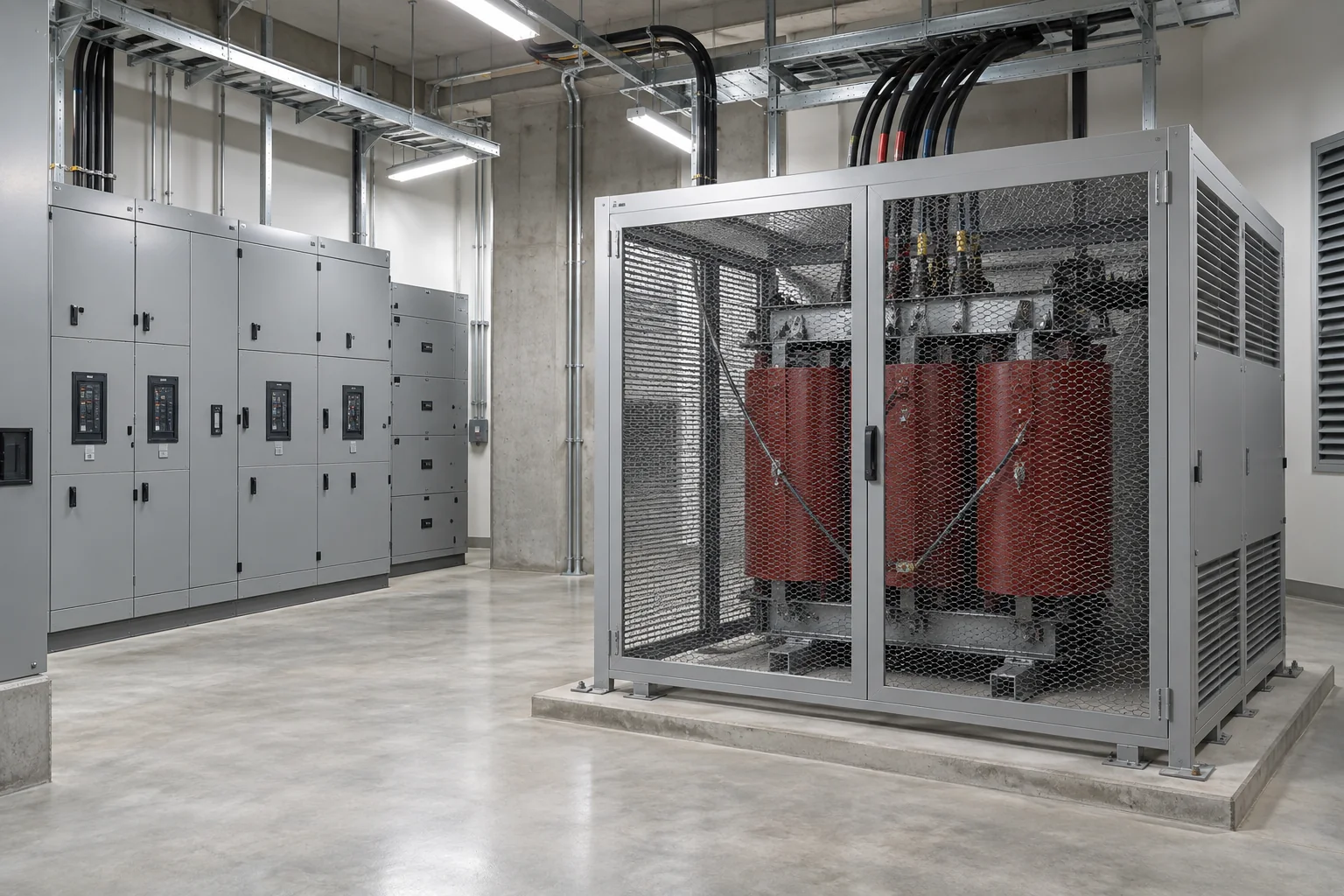
Commercial, transport and industrial buildings place the transformer inside a wider distribution arrangement.
Coordinate equipment access, heat rejection and the connection to adjacent switchgear or busbar before fixing the exact unit.
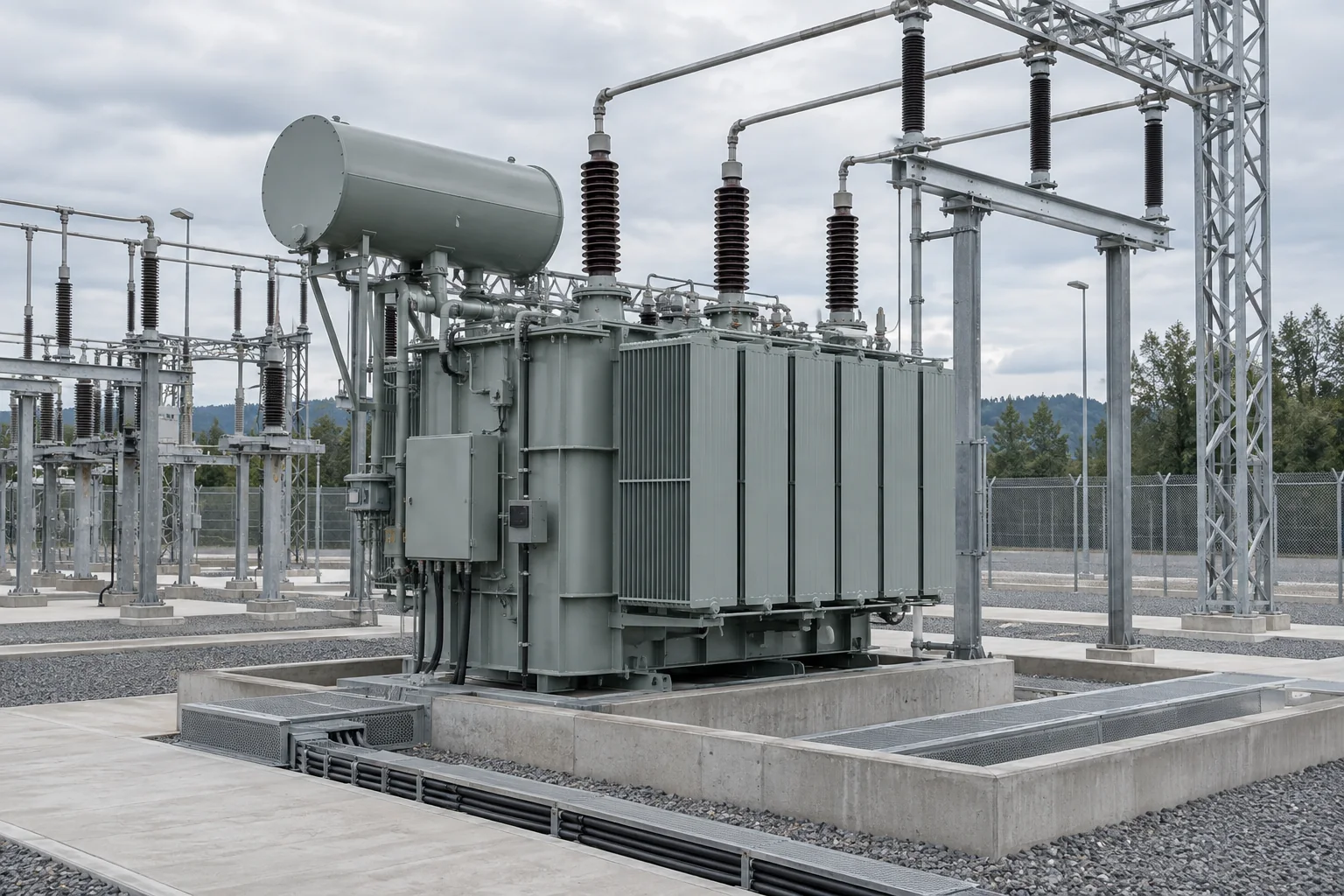
The transformer works with station switching, protection and civil works rather than as an isolated item.
Place it within the station scheme; allocate foundation, cable and oil-management responsibilities when oil-filled equipment is proposed.
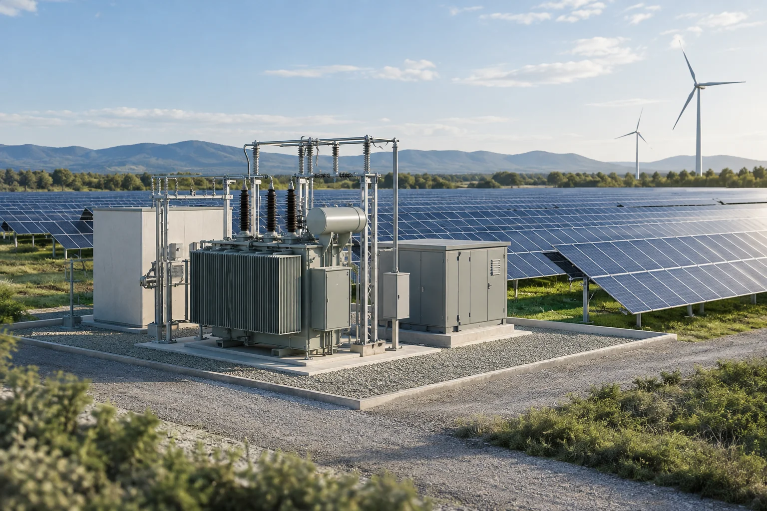
Generation projects place transformer duty between generation equipment and a collection or grid circuit.
Decide whether the scope is a standalone transformer or a complete step-up station, then review the operating profile and protection boundary.
Specification questions
Answers to common questions about selection, replacement, scope and documents.
Start with the voltage ratio, capacity basis, installation setting and construction preference. Then compare the proposed unit with the electrical schedule, site interfaces and required documents.
No. Use the existing nameplate and single-line diagram to check electrical requirements, including vector group, impedance and tap arrangement. Compare load duty, footprint and terminal layout, and request model-specific drawings before treating the replacement as compatible.
Check voltage ratio, vector group, impedance, and tap range and settings against the network scheme and existing units. Matching capacity by itself does not establish compatibility.
Define the supply boundary in the project brief. If a complete station is required, identify switching, protection, civil and connection interfaces as well as the transformer duty; confirm the proposed package for that project.
State the required data sheet, outline and connection drawings, applicable test records and compliance documents in the enquiry. Confirm availability and applicability for the exact model before using them for procurement.