Phone:
(701)814-6992
Physical address:
6296 Donnelly Plaza
Ratkeville, Bahamas.

Phone:
(701)814-6992
Physical address:
6296 Donnelly Plaza
Ratkeville, Bahamas.
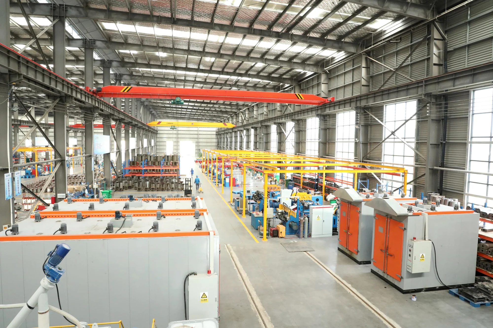
The YBM photovoltaic step-up station connects inverter output to a collection network through a transformer and the specified switching and distribution equipment. Review the electrical interfaces and site layout before selecting the arrangement.
Photovoltaic step-up substation
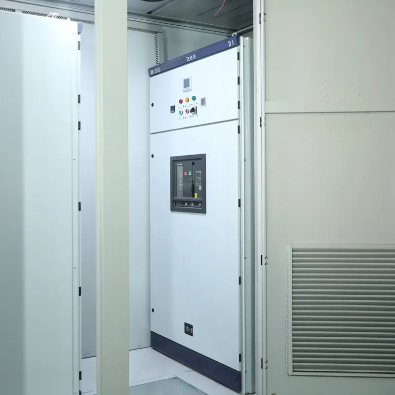
YBM enclosure details, open transformer and cabinet arrangements, and switchgear compartments.
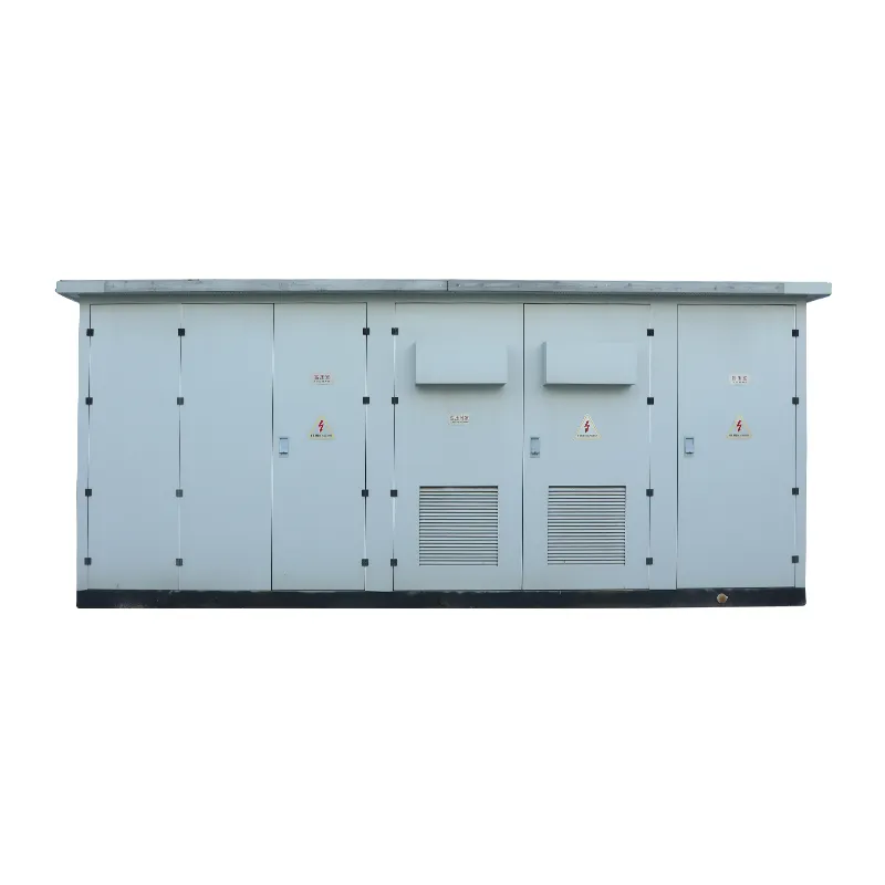
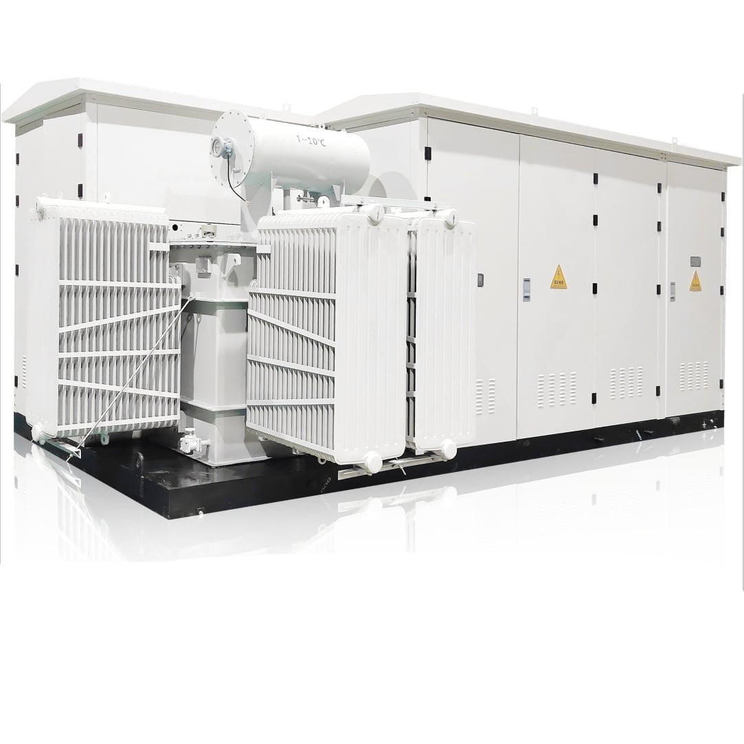
The outdoor package brings a step-up transformer together with high-voltage switchgear and low-voltage equipment for a PV collection connection. Define the equipment schedule, access and cable routes for the selected project arrangement.
Long-face doors, end panels and corner details of the gray enclosure design. Specify door positions, ventilation and internal equipment for the station layout.
The YBM package brings high-voltage switching, a transformer and low-voltage equipment into the PV step-up scope. Define the voltage ratio, transformer capacity and protection scheme from the plant design.
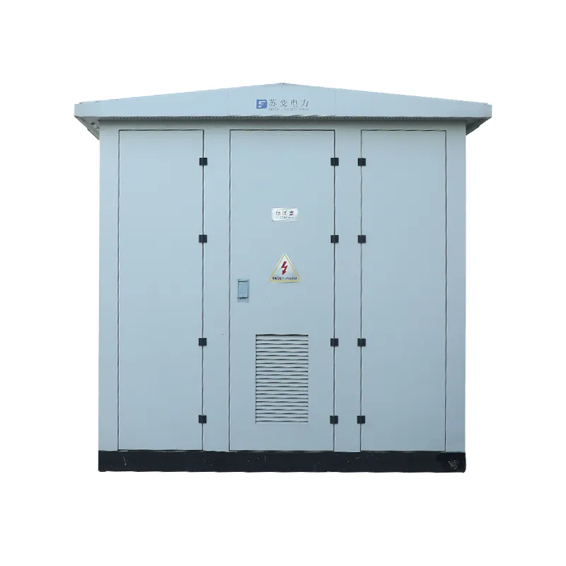
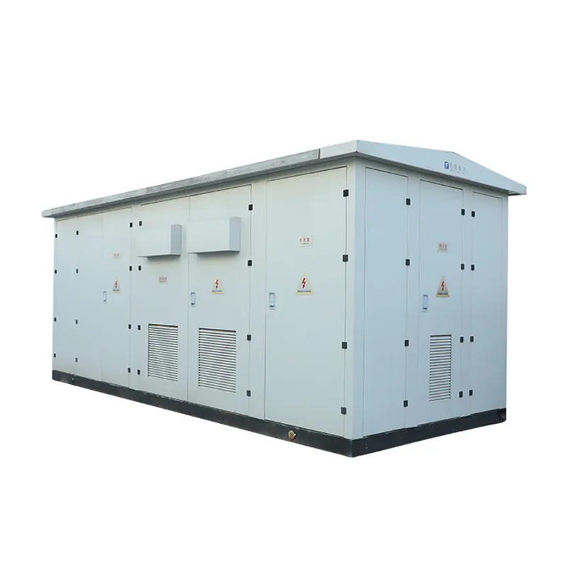
Transformer and cabinet arrangement, with a separate switchgear interior.
Station construction
Coordinate the transformer, switching equipment, cable paths and maintenance access with the plant layout.
An open arrangement places the step-up transformer beside equipment cabinets. Specify switching, protection and cable interfaces for the plant design.
Specification process
Use the inverter block data, collection scheme and site plan to define the electrical duty, package layout and enquiry scope.
Record inverter AC output, collection-side requirements and each circuit’s switching, protection and metering duty.
Use the voltage ratio and block power to set the capacity basis, cooling and loss requirements for the project.
Locate the transformer, high-voltage switchgear and low-voltage equipment; check cable entry, earthing, ventilation, access and foundation.
Confirm the single-line and general arrangement drawings, requested test records, and division of factory and site work.
Use the agreed circuit and supply boundary as the basis for reviewing the proposed station.
Layout comparison
Compare compartment access, cooling, cable routing and maintenance clearances for enclosed and open assemblies.
| Review point | Enclosed station | Exposed transformer and cabinets |
|---|---|---|
| Equipment placement | Show the transformer position relative to the enclosure, and locate the high-voltage and low-voltage equipment on the general arrangement. | Locate the transformer beside the equipment cabinets and define the connections between them. |
| Service access | Check door positions, compartment access and working clearance against the enclosure arrangement. | Check access around the transformer and each cabinet, including the required maintenance space. |
| Cooling and exposure | Coordinate transformer heat rejection, ventilation openings and the specified enclosure protection. | Confirm cooling air paths and outdoor protection for the transformer and cabinets at the site. |
| Cable routing | Mark inverter-side and collection-side cable entries at their assigned compartments. | Show cable entry and interconnection routes between the transformer and adjacent cabinets. |
| Site interface | Confirm enclosure footprint, lifting points, foundation and earthing connection on the general arrangement. | Confirm the assembly footprint, supports, lifting access and earthing connections on the site layout. |
| Approval drawing | Review the compartment layout, door swing, ventilation and terminal positions for the quoted station. | Review the transformer and cabinet positions, clearances and interconnection schedule for the quoted package. |
Quotation information
Bring the inverter block, collection network, transformer duty and site conditions into one project brief. Mark the values already fixed and the decisions still open.
Share the single-line diagram, inverter schedule, collection feeder list and site layout. Add the latest equipment and civil drawings when available.
Application context
Review the connection and site interfaces for utility PV blocks, commercial generation and projects that also include storage.
A plant may repeat station packages across its defined inverter blocks before the collection network.
Confirm inverter AC output, station quantity, protection coordination, collection feeder arrangement and maintenance spacing from the project drawings.
Commercial solar generation may connect through an existing site distribution system. A step-up station is considered where the approved scheme calls for one.
Check the site voltage, export limit, metering, service access and the boundary between solar and facility electrical work.
Adding storage changes conversion, control and export interfaces. The station connection and any shared equipment layout are defined by the approved electrical scheme for each project.
Show PV and storage converter connections, operating modes, protection and metering on the single-line diagram before defining a shared supply package.
Specification questions
Answers to common questions about inverter connections, station ratings, equipment layout and supply scope.
The step-up transformer connects the inverter AC system to the collection network through the specified switching and protection equipment. The plant single-line diagram defines the circuits and the station supply boundary.
Provide the inverter AC output voltage and frequency, power per block, inverter count and connection arrangement. Match the transformer voltage ratio to that AC system and the specified collection voltage.
Confirm the voltage pair, capacity, switching and protection ratings in the equipment schedule and data sheets for the proposed station. The series name alone does not establish the full electrical configuration.
The general arrangement sets transformer position, compartment access, cable entries and service clearances. Specify an enclosed station or open transformer and cabinet arrangement according to the plant layout.
Identify each required device and assign responsibilities in the supply scope. Mark the boundaries for protection, metering, controls, foundation, lifting, cables, earthing and commissioning before comparing station offers.
Share the plant single-line diagram, inverter and feeder schedules, site layout and environmental conditions. List the required equipment data sheets, general arrangement and test records, and mark any project values still open.