Phone:
(701)814-6992
Physical address:
6296 Donnelly Plaza
Ratkeville, Bahamas.

Phone:
(701)814-6992
Physical address:
6296 Donnelly Plaza
Ratkeville, Bahamas.
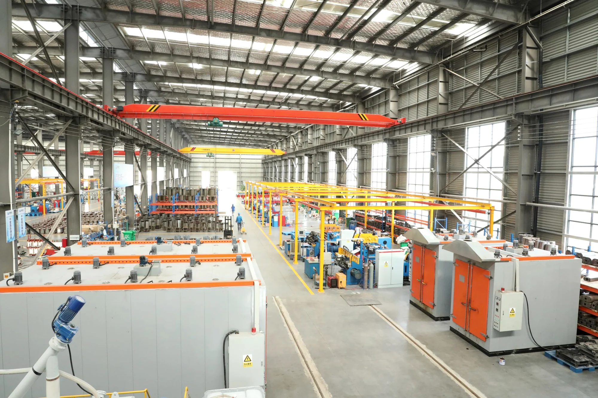
KYN28A metal-clad switchgear, GGD distribution cabinets and GCS draw-out switchgear answer different circuit needs. Use the single-line diagram, feeder schedule and site conditions to define the cabinet arrangement and its ratings.
Product models
Compare five models by circuit duty, switching arrangement and service access. Medium-voltage switchgear and low-voltage distribution cabinets have separate ratings and construction requirements.
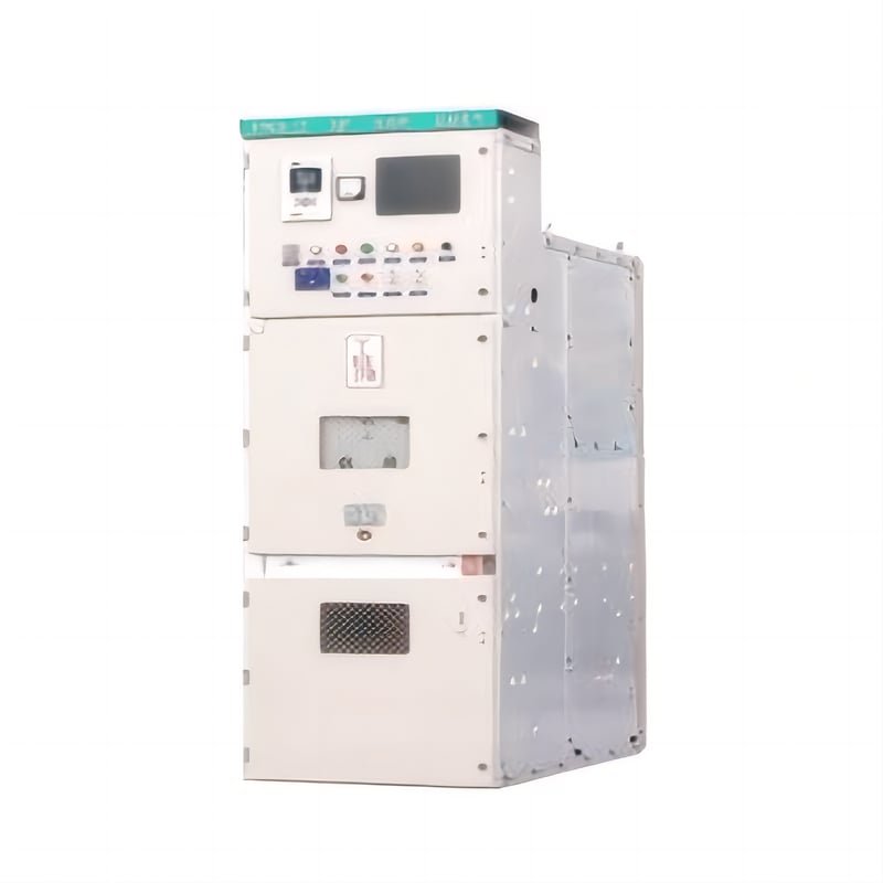
Indoor withdrawable switchgear for a 12 kV circuit. Define the breaker, protection and panel arrangement from the feeder study.
12 kV · 50 Hz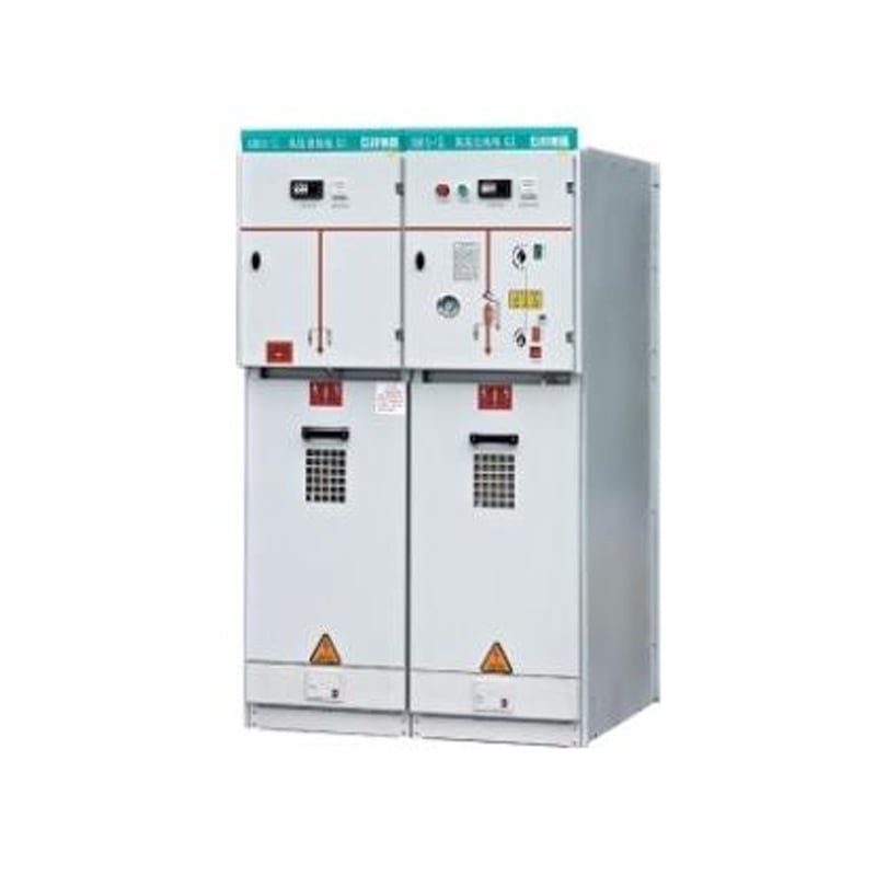
Compact ring-network switchgear with a three-position SF6 load switch. Confirm circuit functions and insulation details for the quoted arrangement.
12 kV · 50 Hz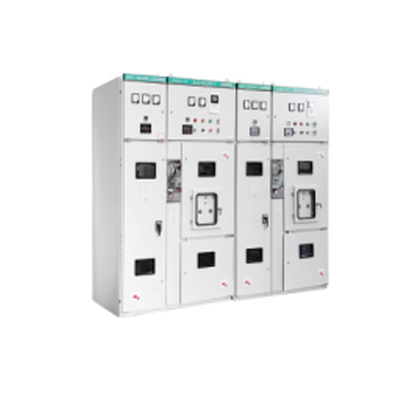
Fixed metal-enclosed ring main unit for ring-network supply points. Match switching and operating options to the circuit scheme.
12 kV · 50 Hz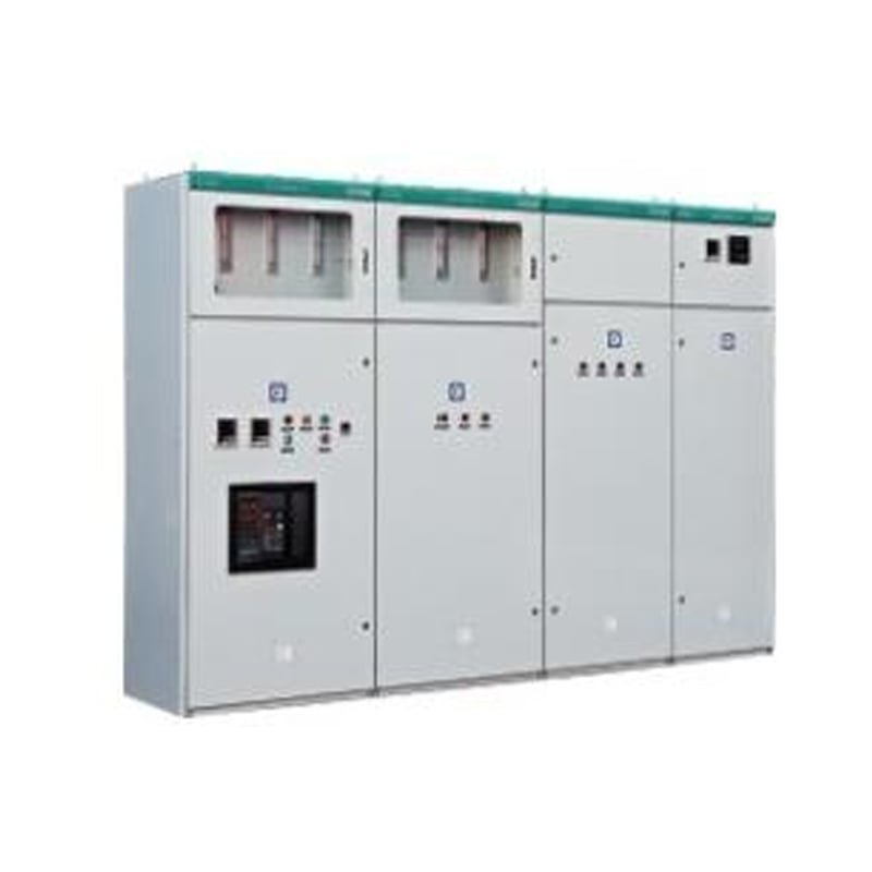
Low-voltage distribution cabinet for incoming and outgoing circuits. Set busbar, protective devices and feeder arrangement from the LV schedule.
AC 380 V · 50 Hz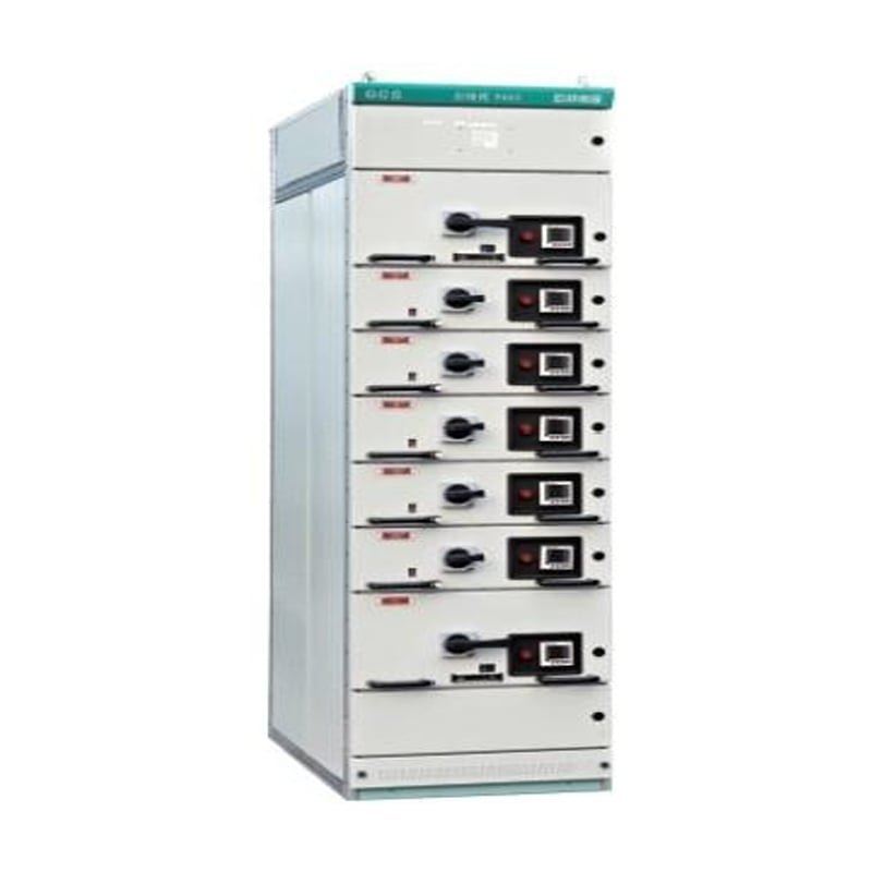
Modular low-voltage lineup with draw-out functional units. Match unit functions, circuit protection and maintenance access to the feeder list.
380 / 660 VModel options cover withdrawable MV breakers, ring-network switching, fixed LV cabinets and LV draw-out units.
Discuss a cabinet requirementKYN28A-12 is indoor metal-clad withdrawable switchgear for a 12 kV, 50 Hz system. Confirm the breaker carriage, protection, interlocks and cable connection with the proposed panel drawing.
Match the panel ratings and construction to the specified feeder duty.
| Rated voltage | 12 kV |
|---|---|
| Rated frequency | 50 Hz |
| Construction | Indoor, metal-clad, withdrawable breaker arrangement |
XGN15-12 is compact ring-network switchgear for 12 kV distribution with a three-position SF6 load switch. Confirm insulation, circuit functions and interlocks for the quoted configuration.
Specify the voltage rating, insulation arrangement and circuit functions for the selected panel.
| Rated voltage | AC 12 kV |
|---|---|
| Rated frequency | 50 Hz |
| Load switch | SF6, three-position |
HXGN15-12 AC is a fixed metal-enclosed ring main unit for 12 kV, 50 Hz indoor distribution. Select the switching and operating arrangement on the project single-line diagram.
Match the selected switching arrangement and panel ratings to the circuit duty.
| Rated voltage | AC 12 kV |
|---|---|
| Rated frequency | 50 Hz |
| Construction | Fixed metal-enclosed unit, indoor mounting |
| Load-switch options | Compressed-air or vacuum type |
GGD AC is a low-voltage power distribution cabinet for AC 380 V, 50 Hz circuits. Define incoming supply, busbar and protected outgoing feeders from the LV single-line diagram.
Check the cabinet ratings against the specified busbar, fault duty and protective-device schedule.
| Rated voltage | AC 380 V |
|---|---|
| Rated frequency | 50 Hz |
| Rated current | Up to 3150 A; confirm for the quoted cabinet |
GCS low-voltage draw-out switchgear uses modular functional units. Define the feeder and motor-control unit mix, busbar duty and service access from the project schedule.
Check the lineup ratings and functional-unit schedule against the feeder and motor-control duties.
| Rated voltage | 380 / 660 V |
|---|---|
| Rated frequency | 50 / 60 Hz |
| Rated current | Up to 4000 A; confirm for the quoted lineup |
| Construction | Draw-out functional units |
Cabinet construction
KYN28A, the two ring-network models, GGD and GCS answer different circuit duties. Compare switching arrangement, access and installation interfaces before fixing the panel lineup.
Use the indoor KYN28A-12 arrangement where the MV feeder scheme calls for a withdrawable breaker and its protection and interlocks.
A ring or distribution switching point needs a defined circuit function, switching duty and cable arrangement. XGN15-12 and HXGN15-12 AC are separate model lines.
Use the GGD AC route to arrange an LV incoming supply, main busbar and protected outgoing circuits from the feeder schedule.
The GCS lineup uses modular draw-out functional units. Build the unit mix around the feeder and motor-control schedule.
Confirm the final construction, ratings and panel dimensions on the quotation drawings for the selected models.
Specification process
Build the schedule circuit by circuit. Keep medium-voltage and low-voltage duties separate, then check the selected panel construction and installation interfaces.
Separate MV breaker and ring duties from LV incoming, outgoing, feeder and motor functions on the single-line diagrams.
Review KYN28A for withdrawable MV breakers; XGN15 or HXGN15 for ring circuits; GGD for LV distribution; and GCS for draw-out LV functions.
Confirm switching, protection, busbar and fault duties by model. Check the proposed lineup, cable entry, access and room dimensions.
Match the panel schedule to the general arrangement and primary and secondary drawings. Identify required test records and the supply boundary.
Use model-specific drawings and data sheets to approve the quoted MV and LV lineups.
Model comparison
Use the voltage side and circuit function to shortlist a model. Compare switching arrangement and service access, then confirm the ratings and layout for each selected cabinet.
| Review point | Medium voltageKYN28A-12 | Medium voltageXGN15-12 | Medium voltageHXGN15-12 AC | Low voltageGGD AC | Low voltageGCS |
|---|---|---|---|---|---|
| Circuit role | MV receiving or feeder circuits using a withdrawable circuit breaker. | Ring-network switching using a three-position SF6 load switch. | Ring-network supply points with the specified load-switch or breaker function. | LV incoming supply and protected outgoing power circuits. | LV feeders and motor-control circuits arranged in draw-out units. |
| Construction | Indoor metal-clad enclosure with a withdrawable breaker carriage. | Compact metal-enclosed form; confirm cabinet insulation and switching arrangement. | Fixed metal-enclosed form with manual or electric spring operation. | Steel cabinet with busbars, switching devices and outgoing feeder connections. | Modular lineup with removable functional units and busbar and cable interfaces. |
| Service access | Check carriage movement, isolation positions and interlocks. | Check load-switch operation, earthing and cable termination access. | Check operation, isolation and access for the selected switching device. | Check component access, feeder isolation and cable connection space. | Check drawer withdrawal, service positions and cable access. |
| Selection drawings | MV single-line diagram, protection schedule and breaker carriage layout. | Ring circuit schedule, switching and earthing scheme, and terminal layout. | Circuit schedule naming each load-switch or breaker option. | LV feeder list, device schedule and busbar and cable layout. | Functional-unit and motor-control schedule with the drawer layout. |
Quotation information
Send the MV and LV circuit schedules with the installation requirements. Identify the selected cabinet models and mark any ratings or layout decisions still open.
Include single-line diagrams, feeder and motor schedules, a room plan and the device list. Existing panel drawings help define replacement or extension interfaces.
Application context
Review circuit duty, installation access and connection interfaces for MV networks, LV loads and changes to existing panel lineups.
KYN28A-12 uses a withdrawable breaker. XGN15-12 and HXGN15-12 AC are separate ring-network model lines with their own switching arrangements.
Mark receiving, ring and feeder functions on the single-line diagram. Confirm the switching, earthing and protection duties, cable terminations and access for each selected model.
GGD AC serves LV incoming supply and outgoing power circuits. GCS uses draw-out functional units for defined feeder and motor-control duties.
Use the load and motor schedules to define each circuit. Review protective devices, busbar duty, cable entry and the operating space required by the proposed cabinet or drawer arrangement.
A replacement panel or lineup extension must match the documented electrical and mechanical interfaces of the installed equipment.
Provide model and nameplate records, busbar and cable positions, primary and secondary drawings, and room dimensions. Confirm connection compatibility, interlocks and installation access before approving the arrangement.
Specification questions
Answers to common questions about MV and LV models, switching duty, cabinet construction and installation interfaces.
KYN28A-12, XGN15-12 and HXGN15-12 AC serve medium-voltage circuit duties. GGD AC and GCS serve low-voltage distribution. Assign each panel to its voltage side and circuit function, then review its model-specific ratings and construction.
Define ring, feeder and transformer functions on the single-line diagram. XGN15-12 uses a three-position SF6 load switch; HXGN15-12 AC needs its selected switching arrangement specified. Confirm load switching, required fault interruption, protection and earthing for each functional unit.
HXGN15-12 AC has a fixed metal-enclosed form, KYN28A-12 a withdrawable MV breaker carriage, and GCS LV draw-out functional units. Match the arrangement to the maintenance and isolation requirements. Check unit positions, interlocks, cable access and operating clearance on the proposed drawings.
Specify device positions, panel order, dimensions and cable entry for the selected models. Coordinate the general arrangement with the primary and secondary circuit drawings, operating clearances and service access.
Compatibility needs an interface review. Provide the installed model and nameplate records, busbar and cable positions, primary and secondary drawings, and room dimensions. Confirm electrical and mechanical connections, interlocks and service access before approving the proposed panel.
Send the MV and LV single-line diagrams, feeder and motor schedules, device list and room plan. State voltage, current and fault duties, model and unit quantities, cable entry, required documents and the supply boundary. Mark any ratings or layout decisions still open.