Phone:
(701)814-6992
Physical address:
6296 Donnelly Plaza
Ratkeville, Bahamas.

Phone:
(701)814-6992
Physical address:
6296 Donnelly Plaza
Ratkeville, Bahamas.

Compare ZW32-12, ZW32-24 and ZW7-40.5 outdoor breakers by rated voltage, fault-interruption duty and installation interface. Start with the feeder study and the pole or bay drawing.
Outdoor vacuum circuit breakers
Compare voltage, current and fault-interruption duty for each complete model. Review installation and control requirements with its ratings.
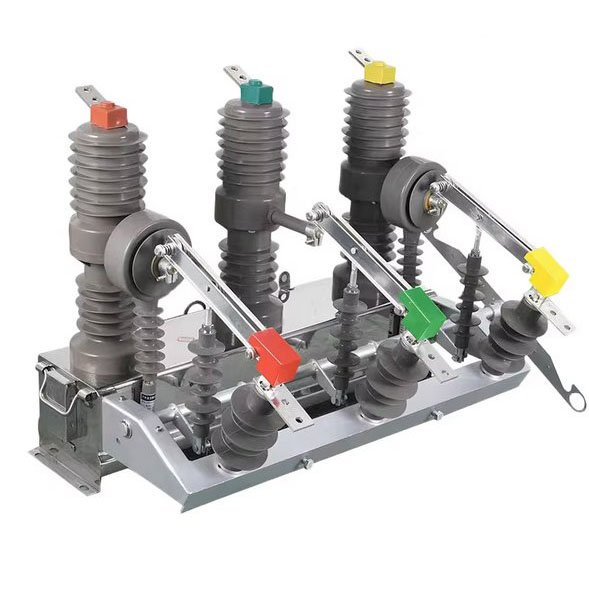
12 kV outdoor feeder breaker. Specify fault duty, pole mounting and the control interface from the circuit drawing.
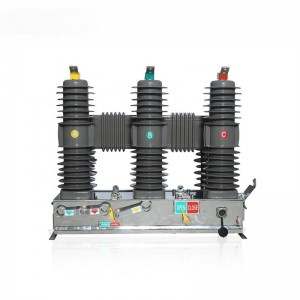
24 kV breaker with linked-post, operating-arm and red-mechanism configurations. Check current and breaking ratings together for the complete model.
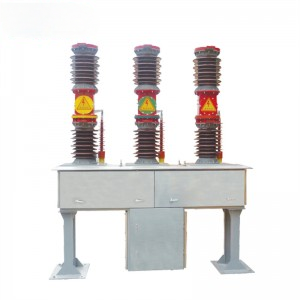
40.5 kV breaker with enclosed-base, cabinet-base and open-frame configurations. Define the mounting and connection layout in the bay drawing.
ZW32-12 is a 12 kV outdoor breaker rated 630 A and 20 kA. The grey three-pole assembly includes insulated poles, operating arms and a base.
Use the selected unit's data sheet and mounting drawing to confirm terminals, operating interface and site clearances.
Review pole spacing, terminal direction and mounting interfaces.
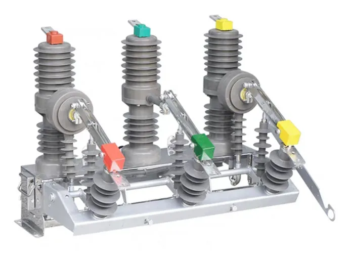
Specify current and breaking duty together under the complete model designation.
| Parameter | Rating |
|---|---|
| Rated voltage | 12 kV |
| Rated current | 630 A |
| Rated short-circuit breaking current | 20 kA |
ZW32-24 configurations include dark linked-post housings, grey posts with operating arms and a red-mechanism package.
Current and breaking ratings must be checked as a pair for the complete model designation.
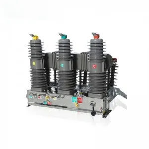
Three dark linked-post housings above a grey mechanism base.
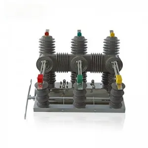
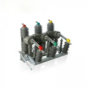
Three grey insulated poles with visible operating arms.
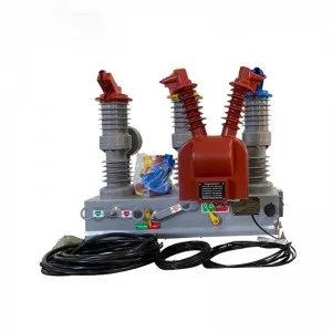
Red central mechanism housing with a coiled control cable.
Specify current and breaking duty together under the complete model designation.
| Parameter | Rating |
|---|---|
| Rated voltage | 24 kV |
| Rated current options | 630 / 1250 A |
| Short-circuit breaking options | 20 / 25 kA |
ZW7-40.5 configurations use a light enclosed base, a rectangular cabinet base or an exposed open frame.
The current and breaking values are separate series options. Check the required pairing on the data sheet for the complete model designation.
Three tall red insulators with an enclosed base, cabinet base or open supporting frame.
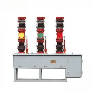
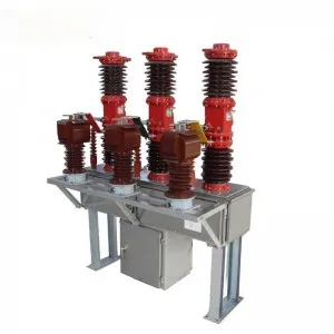
Specify current and breaking duty together under the complete model designation.
| Parameter | Rating |
|---|---|
| Rated voltage | 40.5 kV |
| Rated current options | 1250 / 1600 / 2000 A |
| Short-circuit breaking options | 20 / 25 / 31.5 kA |
Outdoor breaker forms
Compare insulated-pole assemblies, mechanism bases and supporting frames. Match primary connections, mounting dimensions and the control interface to the installation.
12 kV outdoor feeder breaker with three grey insulated poles, operating arms and a base assembly.
24 kV outdoor breaker with dark linked-post, grey operating-arm and red-mechanism configurations.
40.5 kV outdoor breaker with enclosed-base, cabinet-base and open-frame configurations.
Specification process
Start with the circuit duty, then confirm a complete ZW32 or ZW7 rating, the control interface and the installation drawings.
State the voltage class, normal current, calculated short-circuit current and switching role at the circuit position.
Compare ZW32-12, ZW32-24 and ZW7-40.5 by voltage class; verify the current and breaking ratings together on the selected model’s data sheet.
Set out trip and close commands, control supply, auxiliary signals and the protection scheme’s interface with the offered mechanism.
Check terminal geometry, supports, clearances and control wiring on the proposed drawings; list the required data sheet and test records.
The agreed circuit duty and configuration drawings provide a basis for assessing the proposed breaker.
Series comparison
Select the voltage class, then confirm the current and breaking ratings together for the complete model. Match the selected configuration to its installation drawing.
| Review point | ZW32-12 | ZW32-24 | ZW7-40.5 |
|---|---|---|---|
| Rated voltage | 12 kV | 24 kV | 40.5 kV |
| Rated current options | 630 A | 630 or 1250 A | 1250, 1600 or 2000 A |
| Short-circuit breaking options | 20 kA | 20 or 25 kA | 20, 25 or 31.5 kA |
| Configurations | Grey three-pole assemblies with operating arms. | Dark linked-post, grey operating-arm and red-mechanism forms. | Enclosed cabinet-base and exposed open-frame examples. |
| Installation drawing | Check support points, pole spacing, terminal positions and operating-arm clearance. | Match the selected mechanism package, terminal arrangement and support points. | Match the selected cabinet or frame, mounting base and primary connection clearances. |
Quotation information
Provide the circuit duty, control scheme and installation drawing together. Identify fixed ratings and any configuration decisions still open.
A single-line diagram, protection schedule, control drawing and pole or frame layout help define the breaker package. For replacement work, include the existing nameplate and connection measurements.
Application context
Review pole, frame and replacement interfaces together with the selected breaker ratings and protection scheme.
A pole-mounted feeder installation needs the breaker, support and protection interfaces defined together.
Check conductor approach, support dimensions, terminal clearances and operating access. Specify the operating supply and relay or controller interface required by the network.
A breaker selected for an outdoor bay must fit its supporting frame, primary connections and operating access.
Review base dimensions, phase spacing, cable or bus connections, service space and site conditions. Confirm the control wiring against the selected mechanism package.
Confirm a replacement against the existing nameplate, installation measurements and control drawing before choosing the complete model.
Provide mounting centers, terminal positions, operating supply, relay inputs and auxiliary-contact requirements. Confirm current and breaking duty for the exact model designation.
Selection questions
Ratings, control interfaces and installation details to confirm for the quoted breaker package.
Start with the system voltage and required circuit duty. Confirm continuous current, breaking and withstand requirements together for the complete model, then review its insulation, installation and control interfaces.
Select continuous-current and breaking-duty ratings together for the complete breaker model. Use a combination confirmed by that model’s rated-data sheet.
State the relay or controller, sensing inputs, operating supply, commands and auxiliary-contact requirements. Define the quoted controls, supports and accessories separately from equipment supplied by others.
ZW32-24 configurations differ in pole housings and operating mechanisms. ZW7-40.5 arrangements use an enclosed base, a cabinet base or an open frame. Select the mechanism, primary connections and support layout with the required model rating.
Provide the existing nameplate, mounting dimensions, phase spacing, terminal positions, operating supply and control drawing. Replacement compatibility depends on mounting, primary terminals and control wiring as well as the electrical ratings.
Send the single-line diagram, duty and protection schedule, pole or frame layout, control requirements and quantity. Identify the supply boundary and the data sheets, drawings and test records needed for project review.