Solicitar presupuesto
Indique el equipo y los requisitos del proyecto. Si necesita ayuda para elegir un modelo, describa la aplicación.
¿Tiene planos o especificaciones? Envíelos a [email protected] con la referencia del proyecto.


A compact substation foundation can be released after the responsible parties approve one coordinated set. Overlay the vendor general arrangement at the exact revision being manufactured on the civil, cable, earthing and drainage drawings at their applicable revisions, using one datum and one orientation. Check the bearing points, duct inverts, pit depth, earth connections, entry centrelines and door envelopes against that coordinated set. Releasing affected civil work early can turn a drawing mismatch into site rework.
This article works through the interfaces in the order a project actually meets them, then uses a fictional clash to show why a pour would be held and sets out who signs what before concrete goes in. It stays with the physical objects: what each drawing controls, what each party delivers, and which decisions become irreversible at which stage.
The general arrangement (GA) converts the ordered configuration into geometry. Use the GA and its referenced controlled drawings to identify the enclosure plan and elevation, operating face, HV and LV ends, door geometry, base outline, bearing points, cable entries and terminal positions. Confirm which drawings carry the earthing terminal, masses, lifting information and the separate plinth, duct, foundation and earthing details.
That last part is the point people miss. A GA is a hub document, not a complete set. The published TasNetworks Tyree kiosk GA, for example, applies to named variants, distinguishes the HV end from the LV end and shows open doors, while its notes direct the reader to separate and configuration-dependent plinth, duct/conduit, earthing and foundation drawings. The GA tells you where the interfaces sit; it does not design them for your site.
Before anything is compared, freeze four fields:
Check the orientation before comparing dimensions. If the vendor sheet uses the operating face and the civil drawing uses the site grid, record the translation or rotation between them. Once both are expressed on the same basis, compare coordinates at the same reference plane. An assumed rotation can hide an offset that matters later.
Issued for Construction (IFC) is a drawing status. A project issues drawings for defined construction scope under its approval process. Check which review and release gates the status covers. Confirm that the vendor GA and civil drawing belong to the coordinated revision set and that any applicable hold is closed. Record the overlay check with the release package.
The vendor envelope and the civil design are different documents with different owners. The supplier defines the base and terminal envelope: support point positions and the outline of the base, entry opening coordinates and sizes, gland plate or transit frame arrangement, terminal positions, the earthing terminal location, lifting points and the declared masses. The civil and structural designer converts that envelope into footings, a plinth or slab, reinforcement, anchorage, embedment and site levels, using actual ground information. Neither document can substitute for the other. A foundation drawing cannot tell you where the MV cable box sits, and a GA cannot tell you the allowable bearing pressure under the corner column.
Where the product standard fits. IEC 62271-202:2022 (edition 3.0) is the product standard for AC prefabricated substations for rated voltages above 1 kV through 52 kV. Its public scope covers service conditions, ratings, general structural requirements and test methods for in-scope outdoor, enclosed, cable-connected high-voltage prefabricated substations, at power frequencies up to 60 Hz, and it recognises both walk-in and non-walk-in operation. Use it for what it is: a standard about the accepted assembly. It does not provide your package’s support drawing, your site’s foundation design, your cable route or your utility’s connection rules. Those come from the project specification and the owner or utility requirements that apply to the site.
Two consequences follow. First, the existence of the standard says nothing about the conformance of the particular unit offered; that is a matter of the manufacturer’s declaration and the test evidence for the specific configuration. Second, a site change such as a different plinth detail, relocated duct or altered side opening needs project approval. Where it changes mounting or the tested enclosure arrangement, also check the manufacturer’s configuration and test evidence.

The foundation design starts from numbers the supplier must declare and the structural engineer must receive, not from a shape copied from a previous project.
Inputs from the package. The operating mass is the mass of the complete delivered assembly in service: enclosure, switchgear, transformer and any insulating liquid, busbars, accessories. Transport modules matter separately, because a compact substation may ship as a single unit or as sections, and each module has its own mass, its own lifting arrangement and its own centre of gravity. Lifting data — the lifting points, the slinging arrangement, whether a spreader beam is needed — governs how the unit can be set down and, later, removed. The centre of gravity helps the structural designer assess eccentricity. Use the supplier’s support reactions or approved loading information at defined bearing points for the actual installation. Keep operating support loads separate from transport, set-down and lifting cases.
From reactions to support type. Bearing points map onto one of a small number of arrangements: individual pad or strip footings under defined beams, a continuous reinforced slab or plinth, a raft where ground conditions demand it, or a surface-mounted arrangement on a prepared base. The ABB compact secondary substation installation manual shows exactly this logic in practice: it differentiates support arrangements for different site and base conditions rather than presenting one universal detail. That is the correct direction of derivation. The approved support arrangement must suit both the unit’s bearing and mounting requirements and the project’s loads and ground conditions.
Anchors, tolerances and grouting. Compare the supplier’s mounting and restraint details with the structural design. A cast-in, channel or post-installed anchor option needs approval for the actual base, loads, concrete, edges, reinforcement and embedment. Where the design uses grout, coordinate the specified grout and bearing detail with anchor projection, embedment and the accepted level and alignment tolerances. Record the tolerances on the controlled drawings and use those values at the survey hold point.
What the structural and geotechnical engineer owns. Bearing capacity and settlement, frost depth where it applies, design flood level and uplift where it applies, seismic and wind actions where they apply, load combinations, reinforcement design, concrete cover, embedment and the coordination of every cast-in item. The equipment supplier does not own any of that, and the civil contractor does not own the equipment loads. The owner’s project manager owns the interface between them, which in practice means owning the transmittal that puts the supplier’s declared loads into the structural designer’s hands as a controlled document.
There are no universal footing dimensions. A standard foundation detail published in a utility’s catalogue applies to that utility’s equipment in that utility’s service conditions. The TasNetworks kiosk substation standard makes the dependency explicit: it connects the use of a standard foundation to an assessment of site ground conditions and requires an approved alternative where the standard arrangement is unsuitable. Transplanting a plinth geometry, a conduit arrangement or an earthing detail from such a document into another project is a design change that nobody signed, and it removes the ground assessment that made the original detail valid.
Identify the delivered build, not the family. The Tyree GA carries a mass schedule for the named variants it covers, which is a useful reminder that the number to design against belongs to the actual delivered configuration — transformer rating, switchgear type, cable boxes, fittings — and not to the lightest row in a table. Where a project changes the transformer or the LV arrangement after the foundation design is frozen, the mass, the centre of gravity and the entry configuration can all move. For broader context on how the package is assembled and what each compartment contains, see prefabricated substation components and power flow, and for the product family itself, the prefabricated substation range.
Cable entry is a configuration decision that becomes a civil constraint the moment the first duct is laid. Two projects with the same enclosure can need completely different pits, ducts and wall penetrations, so the entry mode has to be settled in the ordered configuration, not on site.
Start by overlaying the cable groups. Identify HV, LV and auxiliary, control or communications cables separately. Confirm any shared route or opening against the project’s segregation, support and seal requirements. For each group record: how many cables and of what construction; which face or floor they enter; the opening centreline coordinates on the common datum; the opening size; the elevation or invert level of the associated duct or pit; the entry mode; the gland plate or transit frame; and the cable support arrangement both inside the enclosure and outside it.
Bottom entry brings cables up through the floor into the enclosure or into a cable chamber beneath it. Where the design uses a pit, its internal dimensions, depth, wall positions and incoming duct inverts affect the cable path to the terminal. Check space for the approved pull and termination arrangements and how the design manages water arriving along a duct. Some approved arrangements use a different chamber or duct geometry. Confirm where the supplied base ends and the site civil design begins.
Side entry brings cables in through a wall opening. It depends on the supplier documenting the side-entry arrangement for the ordered configuration: the opening position and size, the gland plate or transit frame, and the internal terminal path and support. Coordinate the external cable support and protection with the site cable designer. Side entry is not simply a hole in a panel — it is a designed penetration with a termination path behind it and a supported cable route in front of it.
Do not assume you can create the opening later. A new side opening in a delivered enclosure can affect structural behaviour, ingress protection, earthing continuity and applicability of the test evidence. Unless the supplier issues an approved arrangement for that modification, with drawings covering the enclosure, the cable path, the sealing and the access, it is not a field decision. For example, NPC Electric’s published data lists bottom and side entry as options and says entry directions and access layouts can vary by project. The takeaway is not that entry can be changed — it is that entry is a selection made inside the ordered configuration, which is exactly why it has to be frozen before the ducts are set.

Configuration dependence goes deeper than the entry mode. The TasNetworks kiosk standard identifies different plinth, civil and conduit details by actual kiosk and electrical configuration, including distinct conduit details for fuse-switch and circuit-breaker arrangements; its standard drawing register distinguishes conduit detail suffixes for different LV arrangements. Within a single product family, then, the duct detail can change with the electrical build. Confirm the duct and opening detail against the exact configuration on the order, not against the family brochure.
Responsibility, stated plainly. Assign the opening, gland or transit interface, and any approved enclosure change to the supplier’s scope. The civil designer owns the site pit and duct geometry. Assign route and pull design to the cable design or installation team, and document which party provides and checks each internal and external support. The owner or utility approves any deviation from its own requirements. When a duct misses, the question “who moved it” is answerable only if those four scopes were written down first.
A practical decision test for bottom versus side entry: is there physically room for a pit of the required depth without undermining paving, foundations or neighbouring services; what is the groundwater and flood situation at pit invert level; what bend envelope does the largest selected cable need at the termination; does the approved arrangement provide access to pull, terminate, inspect and later replace the cable; and are spare ducts required for future cables. Whichever mode survives those questions is the one to put in the order.
A cable opening can align perfectly in plan and still be unusable, because the available height or lateral space on a section may be insufficient.
Two different limits, often confused. While a cable is being pulled, it is under tensile load and passes over rollers and around bends, and the checks include allowable bend while pulling, pulling tension and sidewall pressure at each bend — the force the cable exerts on the inside of the bend per unit of contact length. After placement, the route must maintain at least the cable’s specified minimum installed training radius at the termination and use the approved supports and cleats. These are separate conditions with separate limits. A pull that stays within tension and sidewall pressure can still leave a cable whose installed training radius is impossible in the space available, and a route that accommodates the installed bend can still expose it to excessive pulling loads.
The Southwire power cable installation guide frames the distinction clearly, treating the final training radius after placement separately from allowable bending while under pulling tension, and separately addressing pulling tension, sidewall pressure, clearance, jamming and conduit fill. Those are general engineering references; the governing numbers are the limits published for the selected cable and termination by their manufacturers, and the approved pulling plan prepared for the installation.
What “in section” actually checks. Three things, at minimum:
Add replacement access to the same check. Verify that the approved arrangement lets the cable be withdrawn or replaced, or identify the planned removal method and any equipment that needs to be moved.
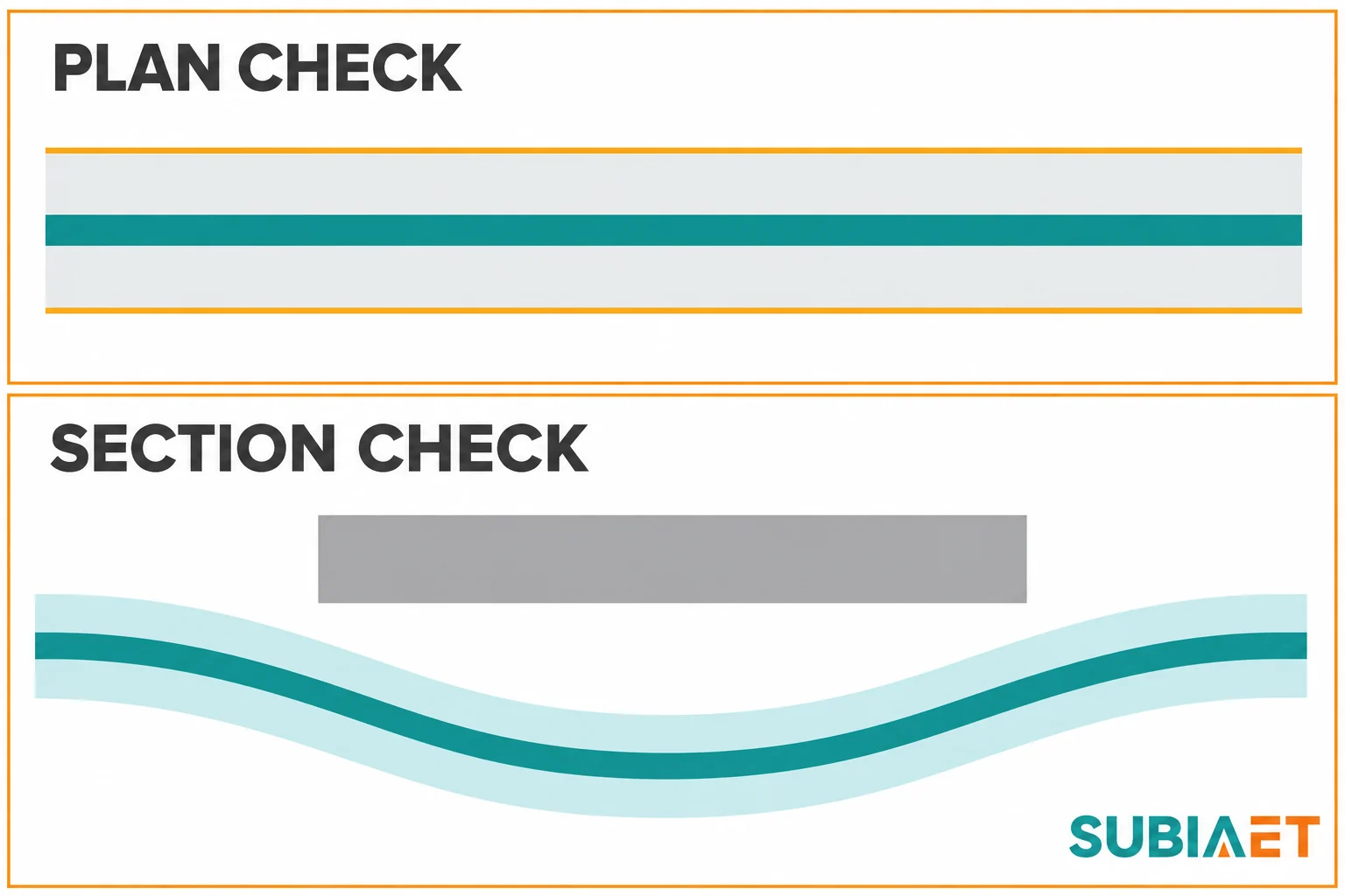
Conduit fill and jamming belong to the same review. Multiple cables sharing a duct interact: fill limits restrict how many can occupy a given bore, and cables pulled together into a bend can jam against each other rather than slide. Resolve these checks before duct sizes and positions are fixed in the civil works. The project’s cable engineer or the installing contractor’s approved pull design is the authority for the numbers; the civil designer needs the resulting duct sizes and invert levels early enough to build them.
Three functions get merged in conversation and must not be merged in design.
Ingress sealing is about the penetration itself: closing the gap between cable and opening to meet the specified ingress or barrier requirements. A seal is a designed assembly matched to the cable type, the opening size and the substrate, installed at the specified location. The Roxtec GIS project case illustrates the underlying pattern usefully: separate external and internal wall openings and below-equipment openings for power, signal and control cables, selection driven by the applicable hazard such as fire or water, and arrangements that leave room for future cables, including pre-sealed sleeves installed pending routing. The pattern, not the brand or any performance figure, is what transfers: the seal is specified per opening, cable group and required exposure, with future capacity considered before the penetration is built.
Fire sealing only where fire separation is required. A barrier fire seal is a specific requirement arising from a fire-rating strategy. Where the fire strategy requires a rated barrier penetration, name the approved assembly, its exact location and inspection access. If the opening also has a water, gas or other requirement, check evidence for the specified combination of opening, substrate, cables and seal.
Spare ducts and closures. A spare duct without a closure is a hole in the ground connected to the inside of your substation. The duct schedule must identify the closure type, its compatibility with the duct and the seal system, who installs it, and who inspects it. A spare that appears on the schedule with no assigned closure and no owner is an open interface, and it is exactly the kind of item that survives to handover because nobody’s signature covers it.
Drainage is not containment. Site drainage removes surface water and groundwater from around the enclosure and the pit and discharges it where the owner or drainage authority permits. Liquid containment holds oil released inside the enclosure or in a transformer compartment so that it cannot reach the environment. An uncontrolled path from a spill area to stormwater could bypass required containment. Show clean runoff and potentially contaminated paths separately on the drawings. Confirm how liquids will be retained, and record an approved discharge route only where discharge is permitted.
ABB’s manual discusses drainage and separately describes an oil collection pit in a selected version, which is a reminder that a collection pit can be a configuration item rather than a default. Confirm whether it applies to the ordered build. The TasNetworks kiosk standard treats site drainage, oil containment and verified site earthing as separate design items, each with its own requirement, which is the right structure: three functions, three checks, three sets of evidence.
Set the datum for water before the levels are fixed. Where applicable, record the design flood level and any required freeboard against the site datum. Coordinate the finished plinth and paving levels, surface grades, pit inverts and any approved discharge point on the same basis. The applicable flood level, discharge consent and containment requirement depend on the jurisdiction and on the equipment — oil volume, type and the presence of any drain-down arrangement — so the design condition must be stated in the project documents rather than assumed from a previous scheme.
Locate the external earthing connection before civil work conceals the route. The approved supplier drawing identifies the package main earth terminal or bar. The ABB manual shows a specific arrangement in which the external earthing conductor is outside the supplier’s delivery. Agree the boundary for the actual purchase. Freeze the terminal location, where any site stub or riser emerges, the approved route and the connection detail. Coordinate cast-in items where required by the design.
List the bonding items separately rather than treating “earthing” as one task: enclosure bonding, HV cable screen or armour bonding, the LV neutral and protective conductor arrangement, and any communications or control earthing. Record who provides and installs package bonds, who designs the site grid and who installs and verifies the site connections. Verification is a separate activity performed after installation, and a location that was coordinated correctly on paper is not a continuity result. Coordination and testing are different records, and the second does not substitute for the first.
Door access is a permanent constraint, not an installation convenience. Record the door swing envelope on the civil drawing so that paving, kerbs, bollards, cable covers, fences, planted areas and future parking do not land inside it. Include the standing space needed to operate the handle and to work with a tool, and, for a walk-in unit, the clear route to exit from inside. ABB’s manual links enclosure alignment to door function, which is the correct way to see it: a door that fouls on a mis-set plinth or nearby kerb is a functional failure of the substation, not a cosmetic one.
Utilities, traffic and impact. Locate existing buried services before setting the pad: water, gas, fibre and other HV or LV circuits may pass under the proposed footprint or the crane position. Then decide vehicle tracking and impact protection, and make sure the protection does not itself obstruct the doors, the entry pit or the lifting route.
Removal and installation route. The unit arrived somehow, and it will have to leave or be replaced at some point. Record the lifting points and the lifting arrangement, the approved lifting equipment set-up position, the outrigger loads imposed on paving or ground, the working radius, and the overhead clearance to be checked against the relevant utility’s rules. Show the physical access and lifting envelope separately from electrical clearances and any approach limits at the site.
Maintainability is the test. For activities authorised at the site, check access to the gauges, controls, seals and bonding points without crossing a drainage channel, climbing over a kerb or opening a door into traffic. If the answer requires a workaround, the layout is not finished, and the cost of the workaround will be paid at every future visit.
The following comparison is a coordination exercise for one assumed package. It is not a standard, a typical detail or a recommendation; the numbers describe only the drawings in this example.
Fictional coordination example only. Dimensions describe the assumed drawings and route for this one package.
Vendor GA Rev B and civil drawing Rev C use the same local origin and orientation. Positive X runs along the operating face; positive Y runs toward the rear. The vendor’s bottom-entry MV opening and the civil duct group are compared at the same plan reference plane. The project’s approved cable-route study calls for a 700 mm unobstructed vertical routing envelope below the entry on the agreed section. That is an assumed project design check, not a cable bend radius.
| Interface | What the two documents state | Check result | Action |
|---|---|---|---|
| Base bearing | Vendor GA Rev B and signed civil support layout use the same support points | Coordinates checked in this example | No support-coordinate clash identified, structural approval still applies |
| MV entry centreline in plan | GA Rev B X 1,100 mm, Y 450 mm; civil Rev C X 950 mm, Y 450 mm | 150 mm offset in X at the same reference plane | Hold duct group location until the aligned route is agreed |
| Routing clearance in section | Cable-route study requires 700 mm clear; civil Rev C shows 540 mm unobstructed | 160 mm short on the agreed section | Hold pit section and confirm full installed and pulling envelopes |
| Spare duct and water seal | Schedule shows the spare duct but does not identify approved closure and owner | Open responsibility/interface | Specify compatible closure and who installs and inspects it |
| Earthing interface | Approved earth plan and vendor drawing identify the same external earth connection location | Location coordinated | Record pre-pour stub and bonding responsibilities; continuity and final checks are separate |
| Civil release | Vendor and site designers must approve the coordinated plan and section | Two unresolved geometry clashes and a missing closure assignment | Owner holds affected pour and duct work until approved revisions and responsibilities are issued |
Only two of these rows involve arithmetic, and both are simple subtractions on a shared datum.
The plan offset. Both documents give the MV entry centreline at Y 450 mm, so there is no discrepancy in the Y direction. In X, the vendor sheet places the entry at 1,100 mm and the civil drawing places the duct group at 950 mm. The difference is 1,100 − 950 = 150 mm, and because the Y values match, the discrepancy is a pure translation of 150 mm along the operating-face direction. Nothing in the comparison says which value is right. The coordinates describe different centreline locations. Hold the duct group until the supplier and site designers confirm the approved route and issue the coordinated drawings.
The section deficit. The approved cable-route study requires a 700 mm unobstructed vertical routing envelope below the entry on the agreed section. Civil Rev C shows 540 mm unobstructed on that section. The shortfall is 700 − 540 = 160 mm. This check says nothing about whether any particular cable can bend inside 540 mm; it says that the drawing does not meet the project’s own stated routing envelope, so the pit section has to be re-examined and both the installed envelope and the pulling envelope confirmed against it before the pit is cast.
Everything else in the table is a non-numeric check with the same weight. The base bearing row confirms that the support point coordinates agree, which removes one class of clash but does not approve the structural design. The earthing row confirms that both documents place the external earth connection at the same location, which is good news that still requires the stub and bonding responsibilities to be recorded before the pour. The spare duct row exposes a missing assignment rather than a geometric error, and a missing assignment is enough on its own to hold a release, because no one has accepted the obligation to close it.
The resolution sequence follows from the findings. Supplier and cable designer first confirm available bottom-entry envelope and checked route, then civil structural designer coordinates the pit/duct revision. A side-entry alternate is only evaluated if the supplier provides an approved enclosure arrangement and cable/structure/seal/access drawings, and owner/utility approval is obtained where required. No improvised cable bends, sleeve offsets, reinforcement cuts or field opening.
Note who can authorise what. The supplier can authorise an enclosure arrangement and its own opening definition; it cannot authorise a change to the site’s duct geometry. The cable designer can confirm the checked route and the envelope it needs; it cannot re-dimension the pit. The civil structural designer can revise the pit and duct section; it cannot move the vendor’s opening. A new coordinated design requires the supplier and the site designers to approve the same plan and section — which is why the civil release row holds the pour rather than nominating one party to resolve it.
The interfaces in this article map onto a small set of owners. Writing them down once, at the start, prevents the situation where a duct is wrong and four parties each believe the other three checked it.
| Interface | Owner of the definition | Owner of the check | Sign-off before pour |
|---|---|---|---|
| GA revision and configuration identity | Equipment supplier | Owner’s project manager | Frozen revision recorded in the transmittal log |
| Support points, loads and anchorage envelope | Equipment supplier (loads and geometry) | Structural designer (bearing, settlement, reinforcement) | Signed coordinated support layout |
| Duct, pit and opening geometry | Civil designer, built to the supplier’s opening coordinates | Cable designer (route, pull and bend envelope) | Coordinated plan and section, not a plan alone |
| Sealing and spare duct closures | Supplier or sealing designer, per opening | Owner or utility, against the applicable hazard requirement | Closure type, location, installer and inspector named |
| Site drainage and containment | Civil or drainage designer | Owner or drainage authority, plus the containment requirement holder | Discharge point approved; drainage route does not bypass containment |
| Earth grid and buried stubs | Earthing designer | Owner or utility | Stub and terminal locations recorded pre-pour; continuity test separate |
| Access, lifting and removal | Owner’s project manager with civil designer | Operations and maintenance representative | Swing envelope, crane position and removal route on the civil drawing |
With owners assigned, the release itself is best handled in stages rather than as one approval event.
Stage one: freeze the revision set. Compile a single record naming the vendor GA revision, the civil drawing revision, the cable-route study revision, the earthing plan revision and the applicable project or utility requirement revision. The record is the artefact that gets compared later. When any one document changes, the record changes and the overlay is reopened. This is the mechanism hinted at by the pattern in published documentation: a legacy GA reference that points to configuration-dependent plinth, duct, earthing and foundation drawings, and a current utility standard whose drawing register distinguishes conduit details by electrical arrangement, cannot be assumed compatible without a revision comparison.
Stage two: discipline checks. Each discipline confirms its own inputs: the structural designer confirms the loads received match the delivered build; the cable designer confirms the route, the pull envelope and the termination space; the earthing designer confirms the terminal and stub coordinates; the sealing designer confirms the assemblies and the spare closures. Each check is recorded against the frozen revision, not against a verbal understanding.
Stage three: pre-pour survey. Have the approved survey team verify opening centrelines, pit outline, earth stubs and anchor templates against the frozen coordinates. Record the results and resolve discrepancies before the affected placement is released.

Stage four: embedded evidence. Record the ducts, sleeves, stubs and anchor positions by survey and photographs before concealment. Record the visible and accessible features again after placement. Include the specified temporary caps and identifiers in the inspection record. Evidence of what was embedded is what allows a rational decision later if something is found blocked or displaced.
Stage five: after-pour or as-built survey. Re-survey the same items against the same coordinates and record the deviations. Refer deviations to the relevant designers and supplier for an approved disposition before equipment placement or cable work. A change to the unit position, gland plate or route must follow the project change process.
Stage six: change control. After a change, reopen the overlay for the affected interfaces and reissue the coordinated revision set as required. A field decision to shift a duct, cut an opening, add a sleeve, drill an anchor or accept a different cable bend is a design change and needs the same approvals as the original design. The behaviour to avoid is the informal adjustment that solves today’s problem and leaves the as-built drawing describing a substation that does not exist.
Practical transmittals and RFIs. Send the supplier’s GA extract to the civil designer as a controlled transmittal with the revision identified, not as a screenshot in a message thread. Raise one RFI per question, with the drawing reference, the coordinate or section in question, and a proposed resolution, so the answer produces a revision rather than a discussion. Where the answer is “the supplier must confirm,” record who asked and when, because supplier confirmation has a delivery time and the pour does not.
Before the concrete is ordered, confirm six things: the GA revision matches the order and the delivered build; the plan coordinates of every opening agree on a shared datum and orientation; the section shows the full routing envelope for both pulling and installed conditions; the sealing, spare duct and closure responsibilities are named; the earth stub and terminal coordinates are recorded; and the access, swing and lifting routes are drawn on the civil set. Any item that cannot be confirmed is a hold on that portion of the works, not a reason to proceed on the lowest-risk assumption.
For projects still upstream of the drawing freeze, the RFQ requirements for renewable energy connections set out what has to be defined before the supplier can even issue a configuration, and FAT versus transformer test evidence explains why the factory evidence for the package is recorded separately from the site civil release described here.
Hold the parts that depend on the equipment interfaces. Early excavation, ground improvement or other separate civil work needs formal phased approval against an issued structural design with verified ground and loading inputs. The bearing points, duct and pit geometry, earth stubs and anchor templates depend on the selected package and coordinated civil drawings. If schedule requires a split, record which elements are released and leave the affected interface zone on hold until the plan and section are approved.
Only if the supplier issues an approved side-entry arrangement for that enclosure, with drawings covering the opening, the enclosure structure, the cable path, the sealing and the access, and only where the owner or utility approval that governs the site is obtained. Cutting or drilling an opening in a delivered enclosure is not a field adjustment: it can affect structural behaviour, ingress protection, earthing continuity and applicability of the test evidence. Without that approved arrangement, the realistic options are to revise the civil works to suit the ordered bottom entry or to change the ordered configuration before manufacture.
Depth is an output, not an input. It comes from the invert level of the incoming ducts, the vertical routing envelope needed for the governing selected cables and terminations, the height of the gland plate or terminal entry, the space needed to pull and terminate, and the clearance required for future replacement. On top of that, the pit invert has to be considered against groundwater and the design flood level, because a deep pit in wet ground changes the sealing, dewatering and structural requirements. There is no universal depth to copy: two sites with the same enclosure and different cable sizes, duct depths and water tables will produce different pits.
Check the purchase scope. The supplier normally identifies the package main earth terminal and internal bonding on its drawing. The project’s earthing designer defines the site grid and connection, and the agreed installation scope names who supplies and installs the external conductor, stub or riser. Record both endpoints and the approved route before the affected works are concealed. Complete the specified continuity and other site earthing verification separately after installation.
No. IEC 62271-202 is a product standard for AC prefabricated substations above 1 kV through 52 kV, covering service conditions, ratings, general structural requirements and test methods for in-scope outdoor enclosed cable-connected units, and it recognises walk-in and non-walk-in designs. It does not supply a site foundation design, a project support drawing, a cable route or a utility connection rule. Those come from the project specification, the structural and geotechnical design, the cable design and the owner or utility requirements. A unit’s conformance to the standard is also a matter of the manufacturer’s declaration and test evidence for that specific configuration, and an altered mounting or enclosure detail may require a review of whether the product evidence still applies.
