Current transformers and voltage transformers serve different secondary circuits. Compare the CT and VT paths by ratio, accuracy duty, burden and terminal arrangement before choosing a unit for a meter or relay.
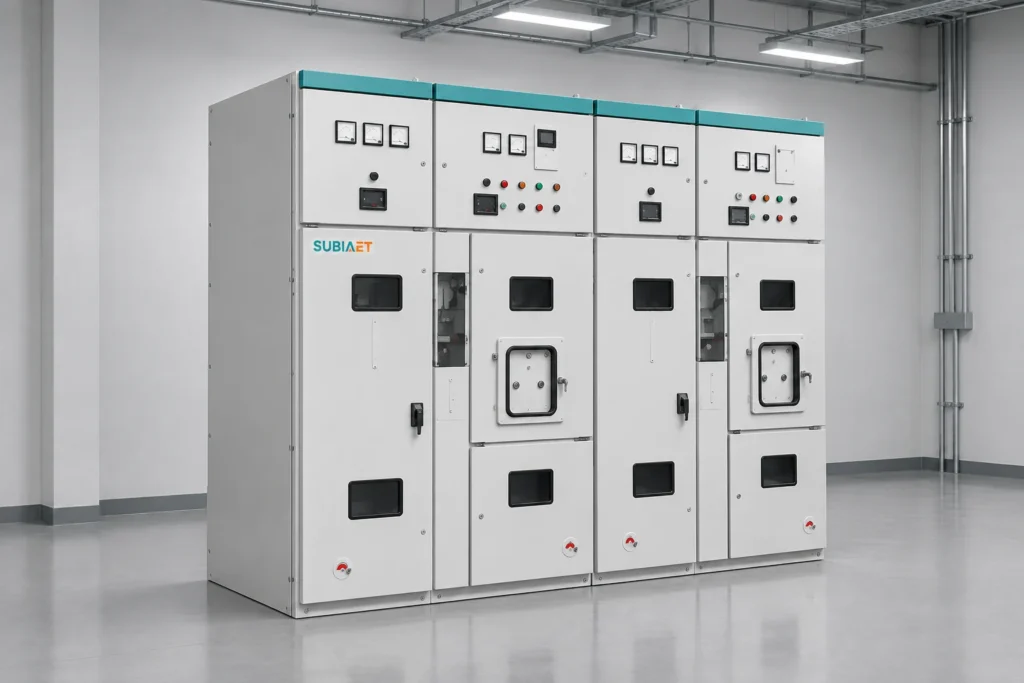
Electrical equipment assembly workshop
High-voltage instrument transformers
Indoor CT and JDZ-10 VT
Specify CT current ratio and secondary current, or JDZ-10 primary and secondary voltage. Set accuracy and burden for the connected meter or relay.
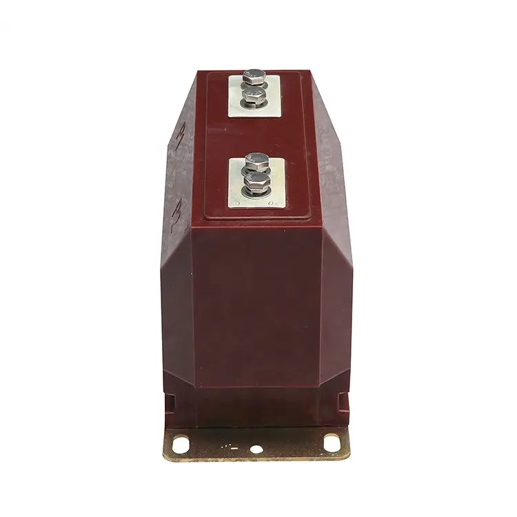
10 kV Indoor Cast-Resin Current Transformer
CT / 10 KV INDOOR
Epoxy-cast indoor CT providing a specified 1 A or 5 A secondary current for metering or protection circuits. Select ratio and accuracy to match the connected device.
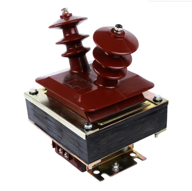
JDZ-10 Indoor Voltage Transformer
JDZ-10 / INDOOR VT
Single-phase indoor VT with 10 kV primary and listed 100 V or 100/√3 V secondary options for voltage input to meters or protection devices.
Compare indoor CT and JDZ-10 VT
Specify ratio, accuracy, burden and connection details for each CT core or VT winding to match the connected meter or relay.
Scroll horizontally to view all columns.
Indoor CT and JDZ-10 VT selection comparison
Review point
10 kV indoor CT
JDZ-10 indoor VT
Primary quantity
Feeder current. Primary current options are 100 / 200 / 400 / 630 / 1000 A; choose the ratio for the circuit duty.
Primary voltage is 10 kV. Confirm the primary connection scheme and voltage ratio for the circuit.
Secondary output
1 A or 5 A secondary current. Match the selected output to the meter or relay current input.
100 V or 100/√3 V secondary voltage. Match the selected output and connection to the device voltage input.
Accuracy duty
0.5 / 1.0 metering and 5P / 10P protection options. Specify each duty and the required core arrangement.
0.2 / 0.5 / 1.0 accuracy options. Confirm the accuracy requirement and winding arrangement for the connected device.
Burden check
Provide the connected meter or relay burden and secondary wiring contribution. Confirm the rated burden for each selected CT core.
Rated burden options are 20 / 50 / 100 VA. Check the connected devices and wiring against the rating of the quoted winding.
Single-phase indoor unit. Check the primary connection, mounting, clearances and available cubicle space.
Connection drawings
Review polarity markings, core identification and secondary terminals on the selected-unit drawing.
Review primary connections, winding identification and secondary terminals on the selected-unit drawing.
Two secondary-signal paths
A current transformer and a voltage transformer feed different signals to meters and relays. Review their primary connections, secondary circuits and panel interfaces separately.
Indoor cast-resin CT arrangement
Indoor cast-resin CT
An indoor CT provides a specified secondary current for metering or protection. The primary conductor, mounting and marked terminals must fit the selected switchgear assembly.
Primary interface
Check the feeder conductor route, installation position, mounting and polarity markings against the proposed CT and panel drawings.
Secondary circuit
Match the 1 A or 5 A option, accuracy duty and connected burden to the meter or relay. Confirm whether separate metering and protection cores are required.
Installation and selection checks+
Provide the feeder single-line diagram and primary current.
State each meter or relay input, accuracy duty and burden.
Confirm core arrangement, polarity and secondary terminal scheme.
Check panel space, conductor geometry and mounting points.
JDZ-10 single-phase VT arrangement
JDZ-10 single-phase VT
The JDZ-10 provides a secondary voltage for measurement or protection devices. Confirm its primary connection, secondary winding arrangement and terminals for the selected circuit.
Primary interface
Set the primary connection and installation position from the project circuit diagram; check insulation, clearances and mounting on the selected-unit drawing.
Secondary circuit
Choose the listed 100 V or 100/√3 V output for the connected device. Verify accuracy, rated burden and winding arrangement as a complete model configuration.
Installation and selection checks+
Provide the system voltage and primary connection diagram.
List the meter or relay inputs, accuracy and connected burden.
Confirm secondary winding count and terminal arrangement.
Check cubicle space, mounting and service access.
Provide a complete rating schedule for each CT core or VT winding, together with outline and terminal drawings.
Specify the CT or VT for its circuit
Start with the primary circuit and meter or relay input, then review each instrument transformer’s ratings, secondary connections and panel fit.
Drawings and device data help define the signal required by the connected meter or relay.
Define the primary circuit
For a CT, provide primary current and feeder duty. For a VT, provide system voltage and the primary connection scheme.
Match the secondary input
State the meter or relay input. Specify the CT current ratio and required cores, or the VT voltage ratio and required windings.
Set accuracy and burden
List metering or protection duty for each output, required accuracy and connected burden, including the secondary wiring.
Review panel and approval data
Check outline dimensions, mounting, primary clearances, polarity and terminals. Request the rated-data sheet and test records for the quoted CT or VT.
Start with the circuit.
Single-line and secondary circuit diagrams
Meter or relay model and input data
Existing nameplate or rating schedule
Panel layout and terminal drawing
Specify CT current outputs and VT voltage outputs with separate rating and connection details.
Circuit drawings and device inputs define the electrical requirement; panel drawings establish fit and connections.
Information for a CT or VT quotation
Provide each instrument transformer’s circuit, secondary input and panel interface. Mark fixed requirements and any ratio or connection decisions still open.
Include the single-line and secondary diagrams, meter or relay data, rating schedule and panel layout. A replacement request also needs the existing nameplate and terminal drawing.
Primary circuit
CT current or VT voltage
For CTs, give primary current and feeder duty. For VTs, give system voltage and the primary connection scheme.
System and installation duty
State frequency, prescribed insulation levels and installation conditions. Include relevant fault-duty requirements.
Secondary requirements
Ratio and device input
State CT current ratio or VT voltage ratio, meter or relay model, and required secondary input.
Accuracy and burden
Specify each output’s metering or protection duty, accuracy and connected burden, including secondary wiring.
Panel and connections
Mounting and primary clearances
Give panel space, mounting points, conductor geometry and primary connection dimensions.
Output and terminal arrangement
Provide the required core or winding schedule, polarity markings, terminal positions and secondary drawing.
Documents and supply
Review documents
List the rated-data sheet, outline and terminal drawings, and test records required for the quoted instrument.
Quantity and package scope
State CT and VT quantities separately, destination and delivery needs. Identify included mounting parts and other accessories.
Instrument transformer applications
Review current and voltage signal requirements for metering, protection and replacement within an existing panel.
Current and voltage for metering
A CT supplies the meter’s current input. A VT supplies a voltage input where the metering scheme requires one. Specify the two signal channels separately.
Match each ratio, secondary input, accuracy and connected burden to the meter. Review the CT core or VT winding arrangement and the terminal diagram for each selected unit.
Inputs for protection relays
The relay scheme defines its current and voltage inputs. Select the CT for the specified protection duty; review a VT input when that scheme calls for one.
Specify CT protection class, current ratio and connected burden. For a required VT channel, confirm the voltage ratio, accuracy, winding and burden against the relay requirements.
Replacing a panel instrument
Existing nameplate data and circuit drawings define the required CT or VT output. Review the replacement’s electrical data together with its fit inside the panel.
Compare ratio, accuracy, burden and core or winding requirements. Check mounting points, primary clearances, conductor geometry, polarity and terminal positions against the selected-unit drawing.
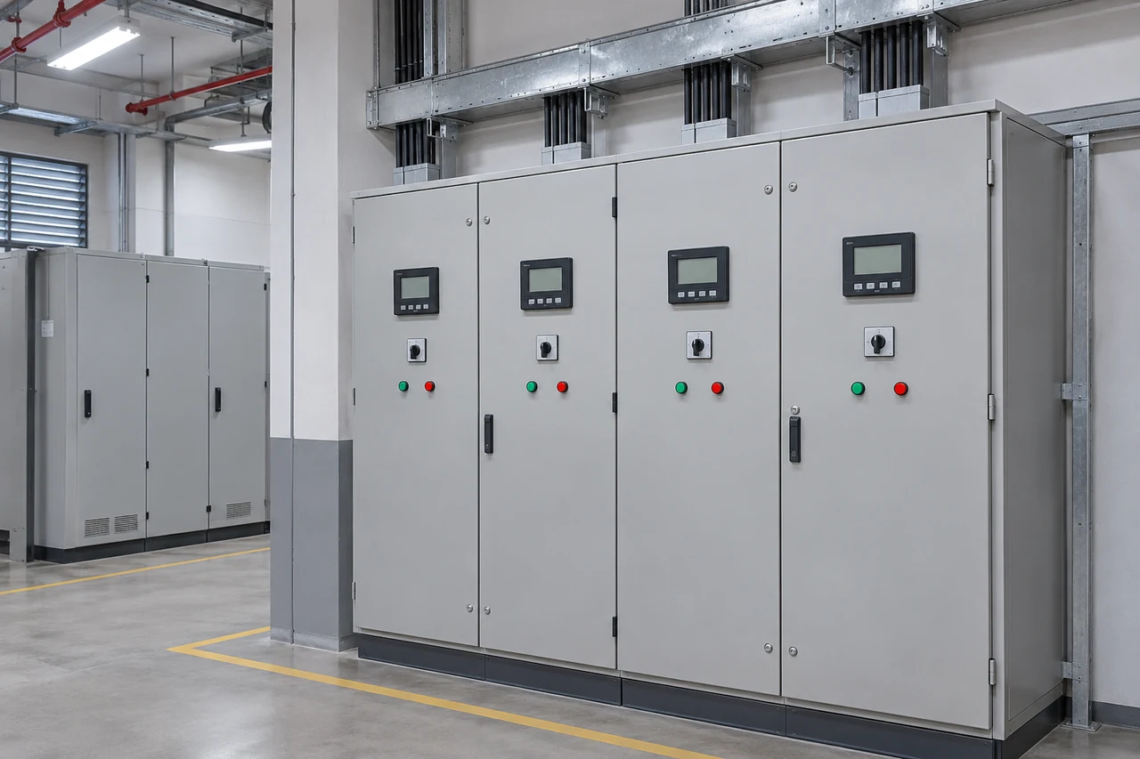
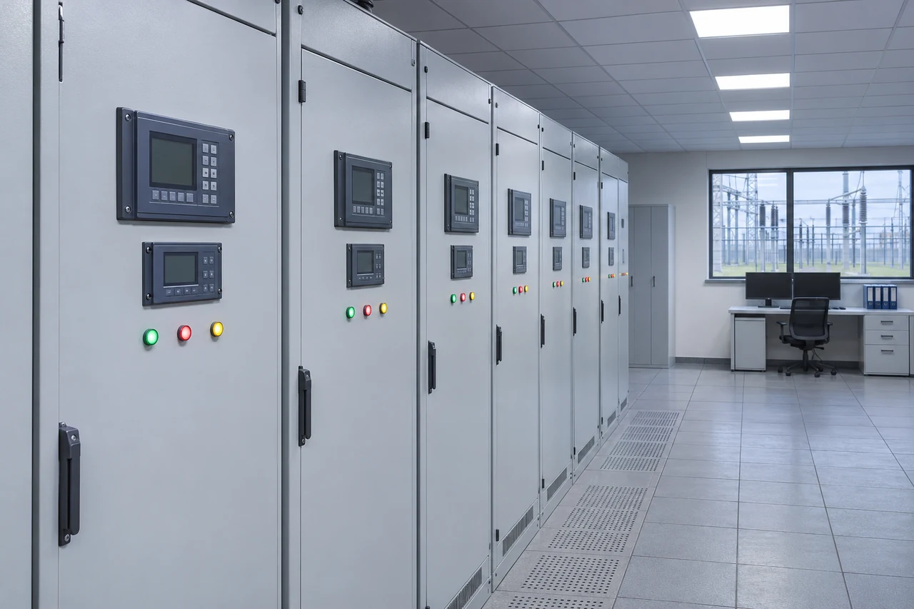
Illustrative application environments.
Questions before selecting a CT or VT
CT and VT duties, secondary outputs, terminal connections and panel replacement.
Review the selected unit’s electrical schedule and installation drawings with the project requirements.
When does a circuit need a CT, a VT or both?
A CT provides a current signal; a VT provides a voltage signal. The metering or protection scheme determines which inputs are needed. Specify each instrument separately against the connected meter or relay and its circuit diagram.
How should ratios and secondary outputs be specified?
For a CT, give the primary current, current ratio and required secondary current input. For a VT, give the system voltage, primary connection scheme, voltage ratio and required secondary voltage input. Confirm the selected combination on the proposed unit’s data sheet and connection drawing.
Can one accuracy class define the complete instrument?
Specify the metering or protection duty, accuracy and burden for each required CT core or VT winding. Include the connected device burden and secondary wiring contribution. The quotation should identify the core or winding arrangement and rated burden for each proposed output.
How should primary and secondary connections be documented?
For a CT, show the primary conductor, polarity markings, core identification and secondary terminals. For a VT, show the primary connection, winding identification and secondary terminals. Include the mounting and outline drawing for the panel layout.
What must be checked for a panel replacement?
Provide the existing nameplate and primary and secondary drawings. Review ratio, accuracy, burden and core or winding duties alongside mounting points, conductor geometry, clearances, polarity markings and terminal positions. Confirm electrical requirements and physical fit on the proposed replacement drawings.
Which documents and scope details help prepare a quotation?
Share the single-line and secondary diagrams, meter or relay data, rating schedule and panel layout. State CT and VT quantities separately, required accessories and delivery needs. List the data sheets, outline and terminal drawings, test records and project requirements needed for review, and identify any open selections.
Check the breaking, making, peak withstand and short-time ratings for the actual switchgear configuration. Use the worked example to compare offers on…