GN19 indoor disconnectors and outdoor pole-mounted disconnectors serve different installation paths. Compare cabinet fit, pole support, operating access and earthing interfaces before specifying the isolation point.
Electrical equipment assembly workshop
High-voltage disconnectors
Indoor GN19 and outdoor pole-mounted disconnectors
Review GN19 for an indoor cabinet and the pole-mounted type for an exposed line position. Each needs its own mounting, operating and insulation review before a quotation can be tied to a drawing.
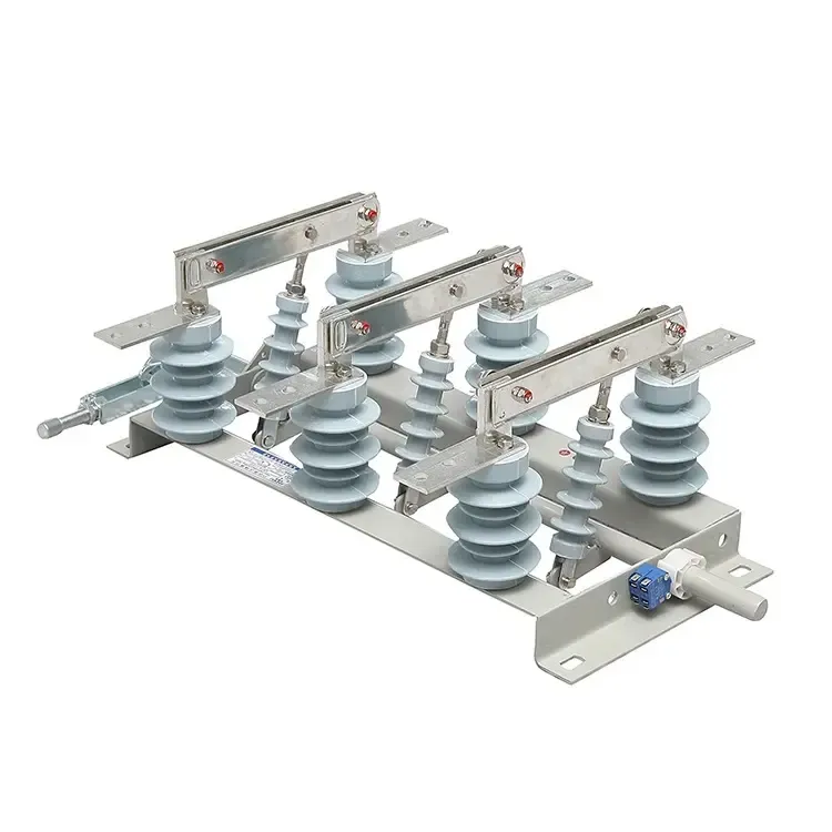
GN19 Indoor Disconnector
GN19 / INDOOR
An isolation point for indoor switchgear assemblies. Review mounting centers, busbar interfaces, operating access and the panel’s earthing interlock before selecting a configuration.
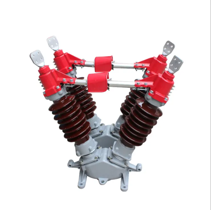
Outdoor Pole-mounted Disconnector
OUTDOOR / POLE MOUNTED
A line isolation arrangement for an exposed pole or structure. Match the support, insulators, conductor terminals and operating reach to the site layout.
Compare GN19 indoor and outdoor pole isolation
Both routes establish an isolation point. Compare their mounting, connections and operating access against the circuit and installation drawings for the selected unit.
Scroll horizontally to view all columns.
GN19 indoor and outdoor pole-mounted disconnector comparison
Review point
GN19 indoor cabinet route
Outdoor pole-mounted route
Installation position
Fit the selected GN19 assembly within the switchgear panel and its specified isolation position.
Position the selected assembly on the pole or support at the required line isolation point.
Mounting interface
Check panel space, mounting holes, phase centres and mechanism clearance on the cabinet drawing.
Check support geometry, brackets, phase spacing and structural loads on the line layout.
Connections
Match busbar and terminal positions to the panel’s incoming and outgoing conductors.
Match line terminals and conductor approach to the crossarm or other support arrangement.
Insulation environment
Review electrical clearances and insulation coordination within the complete panel.
State altitude, pollution and weather exposure for external insulation and clearances.
Operation and earthing
Coordinate the cabinet operating mechanism, position indication, earthing and interlocks with the panel scheme.
Define linkage, operator access and the line earthing procedure for the selected installation.
Approval documents
Request the selected-unit drawing with panel outline, terminals and operating interface.
Request the selected-unit drawing with support, conductor connections and operating route.
Indoor and outdoor isolation arrangements
Locate the isolation point in the cabinet or on the line structure. GN19 requires panel mounting and mechanism access; the outdoor route requires a support arrangement and operating path.
GN19 contact blades and insulating supports
GN19 indoor cabinet mounting
The contact blades, insulating supports and operating linkage form an indoor isolation point within the specified switchgear panel.
Panel interface
Set phase centers, mounting holes, busbar terminals and mechanism access against the cabinet drawings.
Operating scheme
Coordinate the shaft, isolation indication, earthing switch and panel interlocks with the selected assembly.
Installation and selection checks+
Provide the panel outline, busbar layout and connection drawing.
Confirm operating access and the mechanical interface.
Define isolation, earthing and interlock responsibilities.
Check clearances and the complete selected-unit designation.
Outdoor support and insulator arrangement
Pole-mounted line isolation
An outdoor disconnector needs conductor terminals, insulating supports and an operating path that fit the pole or structure.
Structure interface
Match the support arrangement, phase spacing and conductor approach to the crossarm or other installation drawing.
Operating scheme
Define the drive linkage, ground-level access and isolation procedure for the selected configuration.
Installation and selection checks+
Provide the line structure and conductor connection drawings.
State altitude, pollution and weather conditions for insulation review.
Confirm support loads, linkage route and safe operating access.
State the required voltage, continuous current and support arrangement.
Specify the isolation point with the circuit
Start with the single-line diagram and operating scheme. Define what must be isolated, which device interrupts the circuit, and how the selected disconnector fits the installation.
These records establish the isolation duty and the interfaces that a proposed indoor or outdoor unit must meet.
Define the isolation boundary
Mark the equipment or line section to be separated, the required open position and the operating sequence on the single-line diagram.
Assign interruption duties
Specify a breaker or other device rated for the required load and fault interruption. An ordinary disconnector is selected for isolation.
Match installation interfaces
For GN19, check cabinet space, terminals and operating linkage. For the outdoor form, check support, line approach, insulation environment and access.
Verify the quoted configuration
Review the selected unit’s rated data, short-time and peak withstand duty, dimensions, position indication, earthing and interlock interfaces against its drawings.
Start with the circuit documents.
Single-line diagram and isolation point
Load and fault interruption scheme
Cabinet drawing or pole layout
Operating, earthing and interlock plan
State rated voltage and continuous current alongside the required insulation, short-time withstand and peak withstand duty.
Withstand ratings describe a device’s ability to survive a specified fault condition; they do not establish load or fault breaking capability.
Information for a disconnector quotation
Give the isolation duty, indoor or outdoor installation and equipment interfaces together. Mark fixed requirements and any decisions still open.
A single-line diagram, cabinet drawing or pole layout, operating scheme and replacement-unit measurements help define the request. Attach the latest available documents.
Electrical duty
System and continuous current
State maximum system voltage, frequency and the continuous current at the isolation point.
Insulation and withstand
Give prescribed insulation levels, short-time and peak withstand requirements, and the fault-duration basis.
Isolation and operation
Isolation and interruption scheme
Mark the isolation point, adjacent breaker or other rated interrupting device, and the approved operating sequence.
Operating interfaces
Identify the drive arrangement, operator access, position indication, earthing and interlock requirements.
Installation and connections
Cabinet or pole mounting
For GN19, give panel space and mounting details. For outdoor units, give support geometry, phase spacing and conductor approach.
Site and terminals
State ambient conditions, altitude and pollution or weather exposure. Show terminal positions and busbar or line connections.
Documents and supply
Drawings and test records
List the selected-unit drawing, rated-data sheet and test records required for project review.
Quantity and delivery scope
State quantity, destination, delivery needs and which supports, linkages and accessories to quote.
Disconnector installation contexts
Review the cabinet, line structure or existing equipment interface together with the isolation duty and operating scheme.
Isolation in indoor switchgear
A GN19 disconnector forms an isolation point within the specified indoor panel. Its contacts, supports and drive must fit the surrounding cabinet equipment.
Review panel space, phase centers, busbar terminals, operating access and the cabinet’s isolation, earthing and interlock scheme.
Isolation on an outdoor line
An outdoor disconnector connects to the conductors and support structure at the planned isolation point. The support geometry and operating route are installation requirements.
Confirm conductor approach, phase spacing, support loads, insulation conditions, linkage clearance and operating access. Coordinate interruption duty with the rated interrupting equipment.
Replacing an existing disconnector
A replacement must meet the existing unit’s electrical duty and installation interfaces. A matching series name alone does not establish interchangeability.
Provide the nameplate, mounting dimensions, phase centers, terminal positions and mechanism details. Check the quoted unit against the existing cabinet or line layout.
Illustrative application environments.
Questions about disconnectors
Isolation duty, indoor or outdoor mounting, operation and replacement interfaces.
Review the selected unit’s electrical schedule and installation drawings with the project requirements.
Can a disconnector replace a circuit breaker?
A disconnector provides an isolation point. Load or fault interruption requires equipment rated for that duty. Identify the adjacent interrupting device and approved operating scheme when specifying the disconnector.
How do I choose between GN19 and the outdoor route?
Start with the installation environment and isolation point. GN19 is reviewed against an indoor panel drawing; the outdoor route is reviewed against its pole or structure layout. Check ratings, insulation, mounting and operating interfaces for the selected unit.
Which interfaces determine replacement fit?
Match the complete model, mounting dimensions, phase centers, terminals and mechanism to the existing cabinet or line installation. Compare the replacement outline and operating drawings with those interfaces.
Which electrical duties should the request state?
Provide system voltage, frequency, continuous current, prescribed insulation levels, short-time and peak withstand requirements, and the fault-duration basis. Withstand duty does not establish load or fault interruption capability.
Which operating and earthing details should the enquiry include?
Define the operating drive, access, position indication and required earthing and interlock scheme. Identify which devices, linkages and supports belong in the quoted package, then review them on the selected assembly drawings.
Which documents help prepare a quotation?
Send the single-line diagram, required ratings, cabinet or pole layout, operating scheme and quantity. For a replacement, include the nameplate and interface measurements. State the data sheet, drawings and test records needed for project review.
Check the breaking, making, peak withstand and short-time ratings for the actual switchgear configuration. Use the worked example to compare offers on…