Request a Quote
Share the equipment and project requirements. If you need help selecting a model, describe the application.
Have drawings or specifications? Email [email protected] with your project reference.

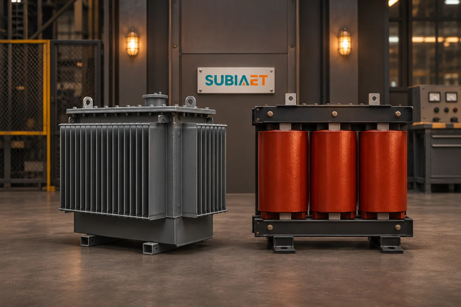
The two constructions differ in where the insulation sits and in how heat leaves the windings, and those two facts ripple outward into the room, the fire design, the civil works and the maintenance plan. That is why the choice is rarely settled by comparing catalogues at the same kVA. It is settled by writing down what the site can actually give the transformer: a heat sink, a spill path or none, an enclosure, and access for the heaviest single item you will ever need to move through that space. Once those constraints are on paper, they can establish which construction is worth engineering first — not because it is better in general, but because it fits this site.
Start with the oil-immersed example, because its heat path is the one people picture most easily. The core and windings sit inside a steel tank filled with a dielectric liquid. That liquid does two jobs at once: it is part of the insulation system, standing between live conductors and between conductors and the tank, and it is the first stage of the cooling system. Heat generated in the windings passes into the surrounding liquid, the liquid moves by natural convection, and the heat is carried to the tank walls and to cooling surfaces — corrugated tank panels, radiators or tubes — where it crosses into the outside air. The tank and its cooling surfaces therefore serve as part of the heat-rejection path. Eaton’s medium-voltage transformer guide describes liquid-filled arrangements and alternatives to mineral oil.
A ventilated cast-resin transformer, which is one form of dry-type construction, removes the liquid stage entirely. In this example, the coil insulation includes cast resin, and the coil assembly is carried in a frame with open passages between and around the coils. Heat flows from the conductor through the resin and the coil insulation to the outer coil surface, and from there into air moving through those passages, either by natural convection or with fan assistance. There is no tank wall acting as the primary heat-rejection surface — the coil surfaces themselves and the air path over them do the work.
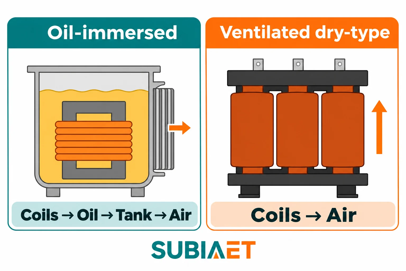
Two clarifications keep this comparison honest.
First, cast resin is an example of dry type, not a synonym for it. Dry-type is a broad family defined by the absence of a liquid-filled main tank, and it includes ventilated open-wound designs, encapsulated designs and sealed non-ventilated designs that behave quite differently in a dirty or humid room. When someone says “dry-type” in a shortlist, the enclosure and cooling variant still have to be pinned down. Eaton’s dry-type overview also describes non-ventilated designs with a different heat path.
Second, both illustrated air-cooled constructions reject their losses to the air around them. The quantity of heat depends on the actual losses and loading of each unit. Neither is a heat-free device. The transformer converts a small but real fraction of its throughput into losses, and those losses become a load on the room or the yard. The oil unit spreads that load over a large tank surface; the dry unit releases it into the air passing through the coil ducts. What changes is where the heat appears inside the building and how much air movement or mechanical assistance the path needs.
Mineral oil is also not the only dielectric fluid in use. Ester-based and silicone fluids appear in applications where the fluid’s behaviour matters for fire, environmental or biodegradability reasons, and the fluid choice changes the fire and containment conversation while leaving the heat-path logic intact. The tank-to-air route stays; the properties of the medium inside it do not.
Selection guidance converges on the same set of inputs: electrical characteristics, the technology chosen, the actual service conditions at the site, local requirements and fire risk. That list is deliberately unglamorous, and it is the right checklist. The table below organises the site-side inputs into five factors that decide whether a construction is plausible at all.
| Site factor | Oil-immersed, liquid-filled tank | Ventilated cast-resin dry-type |
|---|---|---|
| Exposure and enclosure | Confirm the tank, terminals and accessories suit the proposed exposure; indoor installation needs the room and containment reviewed | Coils exposed to the room’s air; outdoor use requires equipment and an enclosure designed for the exposure, with the installed thermal performance confirmed |
| Fire and liquid containment | Liquid inventory creates a spill and fire-load question; containment, drainage and separation are design inputs | No main-tank liquid spill; other combustibles, cable insulation, dust and the enclosure itself still carry fire risk |
| Room heat removal | Losses leave through the tank surface into the room (or to outside air if the tank is outside); the room still has to absorb or extract them | Losses enter the room air directly through the coil ducts; ventilation becomes the primary cooling interface, not a secondary one |
| Space and replacement access | Confirm footprint and mass; radiators and bushings need handling room; replacement needs a route for the actual unit | Confirm dimensions and mass, with clear air inlet and outlet paths plus working space for inspection and cleaning |
| Service needs | Leak checks and fluid level checks where the design provides for them; sealed and conservator designs differ in what can be observed | Dust and dirt checks at terminations and vents; coil cleaning and airflow path integrity matter continuously |
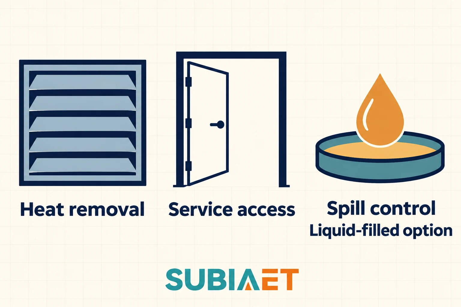
Read the table as a set of questions to answer, not a set of verdicts. The most common mistake is treating indoor/outdoor as a fixed rule attached to a construction type. It is not. Liquid-filled transformers are installed indoors in many buildings; the design then carries a containment and fire-protection burden, and certain indoor liquid-filled arrangements are recognised only under specific site and listing conditions. Equally, dry-type units are installed outdoors — with an enclosure that provides weather protection and, usually, a thermal and access consequence the supplier must design for.
Three separate authorities also need to be kept apart, because they answer different questions and can impose separate requirements:
FM’s transformer loss-prevention guidance explains that indoor and outdoor protection depends on the equipment, the liquid, the surrounding exposure and the location, and that spill containment and emergency drainage can change the design. That is a design-input statement. It does not hand you a separation distance or a containment volume, and this article deliberately does not either — those come from the applicable documents and the authority having jurisdiction over your site. What you should take away is narrower and more useful: containment and drainage are decisions to be made early, because they are civil works, and they are items that need coordination with the civil design.
Abstract factors become concrete quickly. Consider two hypothetical projects with the same electrical duty and very different rooms.
Site A: an indoor electrical room in a building with occupied space next door and no acceptable spill path. The room is on a ground floor, drainage is limited, and the client’s insurer has already asked what happens if the transformer fails. Here a ventilated cast-resin unit is the natural first candidate, because it removes the main-tank liquid inventory from the discussion. The spill question does not need a containment pit or a drainage route, and the fire review shifts to what actually remains: the proposed transformer insulation, cable system, dust accumulation and the room’s other equipment.
Removing the fluid does not remove the engineering. The room still has to take the transformer’s losses. Air has to enter, pass through the coil ducts and leave, and the openings have to be planned for dust, condensation and the quality of the incoming outside air, all of which affect the equipment over years rather than minutes. Access for coil inspection and for eventual replacement has to exist through doors and corridors, not just on a drawing. The fire interface still needs review — “no oil” is not “no fire load.” Review the room ventilation design and the applicable fire, building and insurer requirements together with the equipment. Schneider Electric’s ventilation guide discusses heat removal and condensation together.
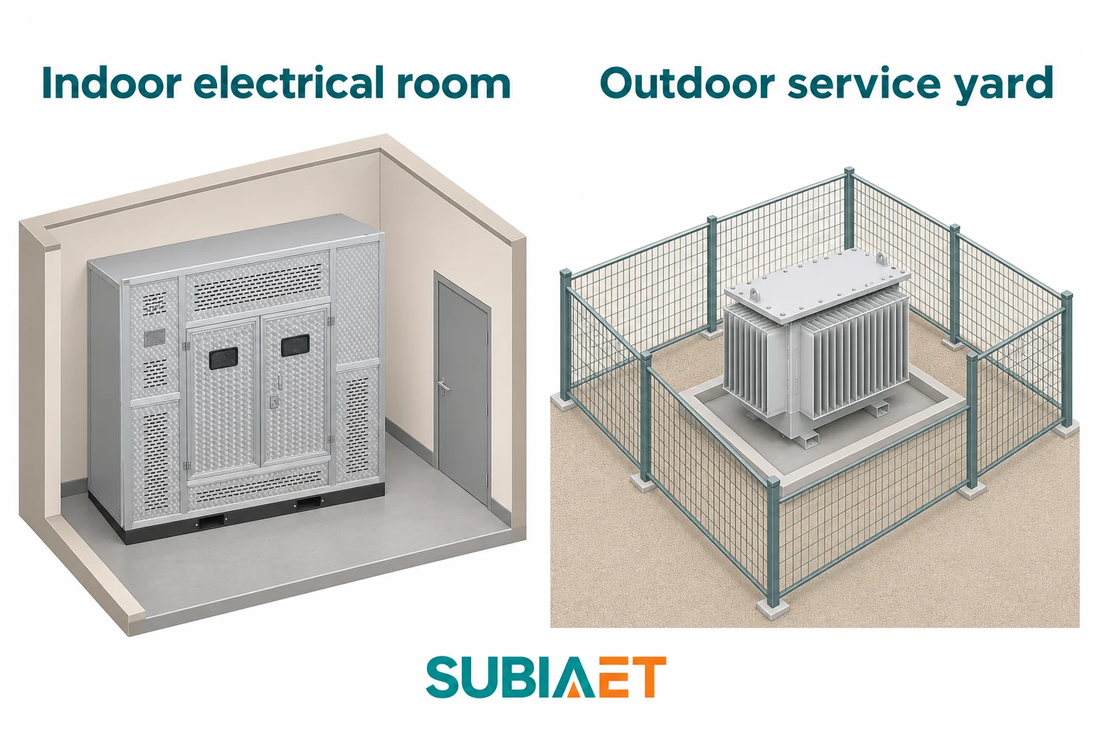
Site B: a dedicated industrial yard with a fenced equipment zone, space for a contained pad, and outdoor service access. Here the containment question has a feasible answer: a bounded area where a spill can be retained, drainage that goes where it should, and room to bring in lifting equipment and a service vehicle. An oil-immersed unit merits evaluation on its own terms — the proposed tank, terminals and accessories must suit the outdoor exposure, the heat path ends at the tank surface in open air rather than inside a room the building has to ventilate, and the service regime is one the site’s own electrical team can support. The checks that matter are the containment detail, the fire exposure to whatever sits around the yard, and whether the maintenance arrangements match what the unit actually needs — a sealed design and a conservator design do not ask the same of the operator.
A dry-type alternative is not excluded from Site B; it simply inherits a different set of requirements. It needs an enclosure that suits the outdoor environment, and that enclosure changes the thermal picture: solar gain, airflow restrictions, dust and condensation can change the thermal and environmental conditions compared with a clean indoor room. The comparison between the two candidates is then a real one — outdoor tank versus outdoor enclosure — rather than a comparison between a catalogue page and a room the site cannot provide.
Neither site gets a selected model, a performance figure or an approved layout from this reasoning. What both get is a shortlist order and a list of approvals to chase.
Once two constructions are on the table, make the quotations answer the same questions. A purchase-price difference may include different assumptions about equipment accessories, room ventilation, containment or other site work. Identify those differences before treating the two transformer prices as the installed-cost comparison.
Give both suppliers the same brief:

The same-kVA trap deserves its own paragraph. Equal rated power is one compatibility check, not a complete replacement specification. Impedance affects fault levels and protection settings, so a replacement with materially different impedance can invalidate a coordination study that was correct for the original. The winding connection, phase relationship and neutral arrangement must suit the existing system. The proposed taps and operating arrangement must suit the supply range and required secondary-voltage performance. Losses decide the heat the room or the enclosure has to handle, which may be the binding constraint in an existing building. And the physical envelope — mass, footprint, terminal positions — decides whether the unit can be installed at all without rebuilding the room around it.
Two further checks are worth adding before you compare prices. First, ask for the loss figures on a stated basis and, where the project warrants it, the factory test regime those figures will be verified against; comparing a quoted loss number with a measured one on a different basis is a common source of dispute. Second, confirm which construction variant is actually being quoted. “Dry-type” covers ventilated, encapsulated and non-ventilated designs with different thermal and environmental behaviour, and “oil-immersed” covers sealed and conservator designs with different service requirements. A quotation that does not name the variant is not yet a quotation you can compare.
For reference points on the two families, see SUBIA’s oil-immersed transformer series and dry-type transformer series. Read the exact proposed configuration and service conditions rather than treating a family label as a specification. If the classification itself is still unclear — insulation type versus phase arrangement versus installation — the overview of types of electrical transformers separates those axes. When a quotation arrives, the entries on the nameplate are a starting cross-check against the brief; see how to read a transformer nameplate.
Write a one-page site brief before contacting anyone. It should state the electrical duty, the ambient and loading assumptions, whether the unit sits indoors or outdoors, what enclosure is expected, what containment is achievable, how the room is ventilated, how a replacement unit would physically enter and leave, and which approvals — electrical inspection, fire authority, insurer, environmental — have to be satisfied.
Send that same brief to both suppliers and require each to answer it item by item, including the loss basis, the outline drawing and the service scope. Where a supplier cannot answer an item, that gap is information: it tells you which assumptions are still yours to make. The shortlist then follows from the site rather than from the catalogue, and the two quotations become genuinely comparable documents.
Some installations permit it. The room, fluid, equipment approvals, spill arrangements, fire protection and heat removal must meet the project’s requirements.
Yes, when the complete unit and enclosure are designed for the exposure. Verify the thermal performance of the installed arrangement as well as weather protection.
A ventilated unit needs its designed air path. For any unit in a room, check how the room will remove the heat it releases, including heat from a non-ventilated enclosure.
Use equal kVA as one screening check. Also verify the electrical characteristics, terminal positions, installed envelope and heat removal for the replacement.
