Request a Quote
Share the equipment and project requirements. If you need help selecting a model, describe the application.
Have drawings or specifications? Email [email protected] with your project reference.


A mine changing power sources, a fab expanding a cleanroom and a battery plant adding formation lines impose different duties on the electrical system. Identify which loads run together and which must stay on during a transfer.
A mine may combine grid supply, onsite generation and storage. Separate essential pumps and ventilation from crushers and conveyors that can be restarted in stages. For a proposed transformer with a dust cover, specify the dust exposure, ventilation and maintenance access for the installation.
Consider a mine where the grid normally supplies the mill and onsite generation can support only part of the load. Identify the dewatering pumps and ventilation fans needed during the interruption. Then list the crushers, conveyors and other loads that the operator can shed and restart in sequence.
| Operating condition | Question to settle | What to request |
|---|---|---|
| Grid connected | Which motors run together, and which starts produce the highest demand? | Request the feeder schedule, starting method and transformer duty for the agreed production case. |
| Onsite supply | What generation or storage remains available, and which motors must keep running? | Ask for a critical-load list and a protection review for this source arrangement. |
| Production restart | Which process steps must return before the mill can restart? | Have the operator define the restart order and the motor supplier provide starting current and duration. Use the same sequence for every bid. |
A fab extension adds process tools, cleanroom air handling, chillers and water systems, often in different phases. Ask the facilities team which processes can tolerate a supply transfer. Where a process tool requires an electrically separate supply, review the isolation transformer requirement with the tool supplier.
For a fab extension, list process tools with defined voltage-disturbance limits separately from the facilities loads serving more than one line. A tool may be idle while the air handling, chilled water and process utilities serving its room are already required.
| Operating condition | Question to settle | What to request |
|---|---|---|
| Tool power | Which tools require ride-through, and what disturbance can each tolerate? | Request the tool vendor’s input limits. Identify any separately supplied conditioning or backup equipment on the one-line. |
| Facilities power | Which air-handling and cooling loads serve both the operating fab and the new room? | Ask for separate normal and maintenance load schedules showing the bus and feeder serving each shared utility. |
| Construction tie-in | Which sections can be isolated for extension while production continues? | Compare the proposed tie-in sequence, spare feeders, bus-extension provisions and works assigned to the site team. |
A cell plant may commission dry rooms before formation lines reach full production. Separate continuous ventilation and dehumidification loads from the formation schedule.
During a phased start-up, dry-room ventilation and dehumidification may be running while only part of the formation equipment is installed. Ask the process supplier for an opening-day schedule and a full-production schedule. Keep test equipment capable of returning power identifiable on both.
| Operating condition | Question to settle | What to request |
|---|---|---|
| Dry-room services | What minimum ventilation and dehumidification duty must continue during a line shutdown? | Request the continuous facilities load and the supply path retained during maintenance. |
| Formation and test | Which cabinets charge together and, where applicable, which can return power? | Obtain the supplier’s AC input and reverse-power limits. Mark the board and protection boundary for the permitted modes. |
| Next production line | Which extra feeders and transformer capacity are needed in the next phase? | Separate equipment installed now from physical space, bus extensions and cable routes reserved for later. |
Trace the new load back to the incoming supply. Select the change closest to your project to see what to mark on the drawings and what to request in the quotation.
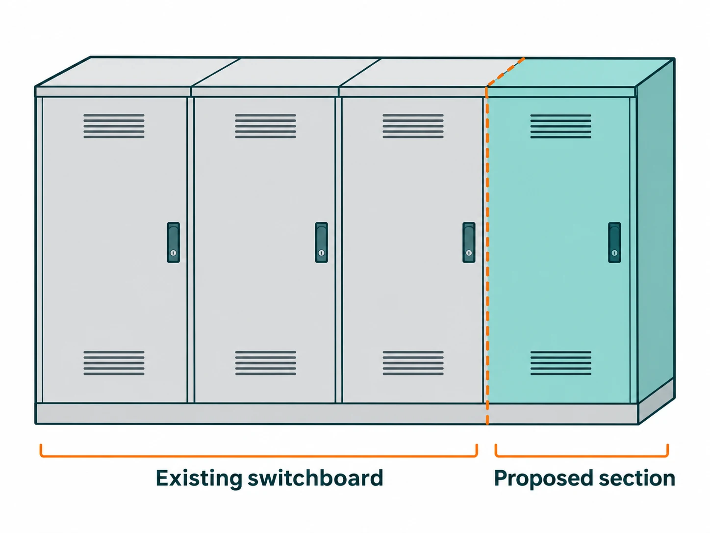
Consider a packaging line added to an operating plant. The drawing shows where a proposed section meets the retained board. Check the electrical and mechanical interfaces before specifying that joint.
Suppose a 1,000 kVA transformer supplies 630 kW and a new line adds 180 kW during the same shift. With balanced, sinusoidal loads at 0.90 lagging power factor, the existing shift draws 700 kVA and the line adds 200 kVA. The 900 kVA total leaves 100 kVA of steady-load margin. Use measured coincident demand, then check motor starting, harmonics, site temperature and feeder ratings. Power factor definition.
Match the circuit schedule to photographs and drawings of the actual board. A spare position alone does not establish that a breaker is installed, the assembly has capacity or there is space to terminate the cable.
Provide the original lineup designation, end-panel drawing, busbar position and available width. Ask for a dimensioned interface drawing and confirmation of compatibility before treating the extension as a direct fit.
Mark the circuits that need to remain available and the planned shutdown window. Assign responsibility for temporary supply where required, the site connection, testing and return to service.
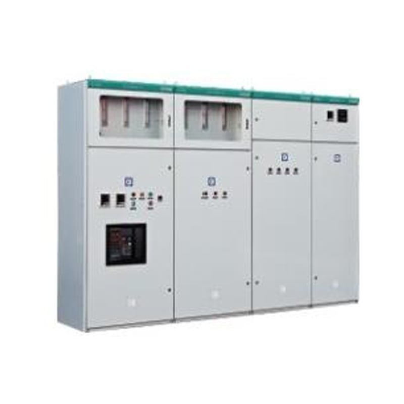
For a board extension, identify the feeder duties and retained busbars. For withdrawable LV units, compare the GCS and MNS lineup ratings.
View MV & LV switchgear
For an indoor transformer proposal, check room access, ventilation, terminal positions and the required load duty.
View Dry-type transformers
For a new or replacement unit, compare installation conditions and electrical duty against the proposed configuration.
View Oil-immersed transformers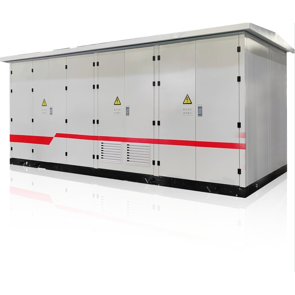
For a new building supply, identify which transformer, panels and internal connections belong in the package.
View Prefabricated substationsSend the existing single-line diagram and mark the production feeders to be added. Keep assumed loads separate from measured demand.
Measured demand, coincident loads, motor starting methods and the operating pattern of the new line.
Transformer nameplate, board schedule, busbar and end-panel drawings, cable entries and available space.
Proposed equipment location, delivery access, the permitted shutdown period and circuits to keep available.
Use one load schedule and identify retained equipment on every bid. Ask bidders to separate feeder work, board modifications and any transformer option.
| Plant change | What to mark on the drawings | What to ask the bidder to price |
|---|---|---|
| Add an outgoing feeder | Identify the new circuit, operating current, protection duty and cable entry. Confirm whether the spare position has a breaker and usable termination space. | Ask for the feeder components, protection and any changes to the existing board. Identify the outage and site work separately. |
| Extend an existing switchboard | Mark the end of the installed lineup, the original make and model, busbar position, enclosure details and available floor space. | Request a drawing of the proposed joint and a list of modifications to the retained board. Ask for a separate-board option if an extension cannot be confirmed. |
| Review transformer capacity | Provide recorded peak demand, the transformer nameplate, the new operating schedule and the starting method for major motors. | Ask the bidder to state the load assumptions behind a transformer proposal and identify any changes required at the MV or LV terminals. |
| Supply a new production building | Mark the new building, incoming supply, cable route and proposed equipment location on the site plan. Identify all external connection points. | Compare separate equipment with a prefabricated station on the same single-line diagram. List external cables, foundations and testing separately. |