Request a Quote
Share the equipment and project requirements. If you need help selecting a model, describe the application.
Have drawings or specifications? Email [email protected] with your project reference.


A battery station imports as well as exports power. A solar-plus-storage plant may share a grid connection across several inverter blocks. Define each operating mode and the AC equipment supply boundary.
A standalone battery station imports power while charging and exports it while discharging. Define the AC terminals of each power conversion system (PCS), the collector voltage and the grid connection point.
A 40 MW export sustained for two hours represents 80 MWh delivered at that measurement point in an idealised example. For the transformer quotation, specify import and export duty, required reactive power, auxiliary demand and AC voltage. The PCS schedule should also state whether its transformer is already included.
| Operating condition | Question to settle | What to request |
|---|---|---|
| Charging | What maximum AC import and reactive-power duty must each block support? | Request the PCS terminal data and the transformer duty for charging, including any coincident auxiliary load. |
| Discharging | What is the permitted export at the grid connection, and how many blocks can export together? | Ask for the collector one-line and the duty at each transformer and switching point. |
| Station services | Which auxiliaries must remain powered when PCS blocks are unavailable? | Identify the supply for controls, cooling and other station services, and who supplies the auxiliary transformer and board. |
PV inverters and batteries may use separate AC feeders or share a converter. The connection diagram determines which transformer and switchgear duties belong in the quotation.
Consider an AC-coupled plant with 30 MW of PV output and a 35 MW grid export limit. While the battery charges at 12 MW, the grid meter shows 18 MW of export, although the PV and battery feeders carry 30 MW and 12 MW respectively. These illustrative flows omit losses and auxiliary loads.
| Operating condition | Question to settle | What to request |
|---|---|---|
| Separate AC feeders | Can PV export while the battery charges from the collector? | If the battery discharges at 12 MW while PV holds 30 MW, potential export is 42 MW. The combined output must fall by at least 7 MW to respect the 35 MW limit in this example. Request the permitted active and reactive power by feeder and operating mode. |
| Shared converter | Where does the inverter supplier’s package end on the AC side? | Obtain the shared inverter’s AC rating and mark the transformer terminals, protection and cabling that belong in the quotation. |
| Phased expansion | Will the next battery or PV block use a spare feeder or require a larger shared connection? | Separate opening-day equipment from later work, and identify the space, terminations and outage needed for the addition. |
Use terminal identifiers from the project single-line diagram. For each interface, assign equipment supply, cable supply and termination as separate responsibilities.
In this example the owner supplies the inverter and the station supplier quotes the step-up package. The external collector cable is a separate schedule item.

Provide the inverter AC data sheet, unit count, operating apparent power and required reactive-power conditions. For a bidirectional PCS, state import and export duties separately.
Give the same terminal designation to the inverter supplier and station supplier. Identify who supplies the link, cable accessories and terminations, and who makes the connections on site.
Show the transformer duty, LV incoming arrangement, MV feeder, auxiliaries and enclosure on the equipment schedule. Request a list of included internal connections and any separately furnished items.
Mark the outgoing terminal, metering point and protection signals on the collector drawing. Assign external cable supply, termination and commissioning responsibilities before comparing bids.
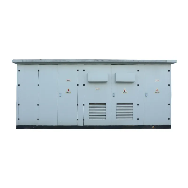
For an integrated PV block, review the YBM station arrangement and identify the external incoming and outgoing terminals.
View PV step-up substations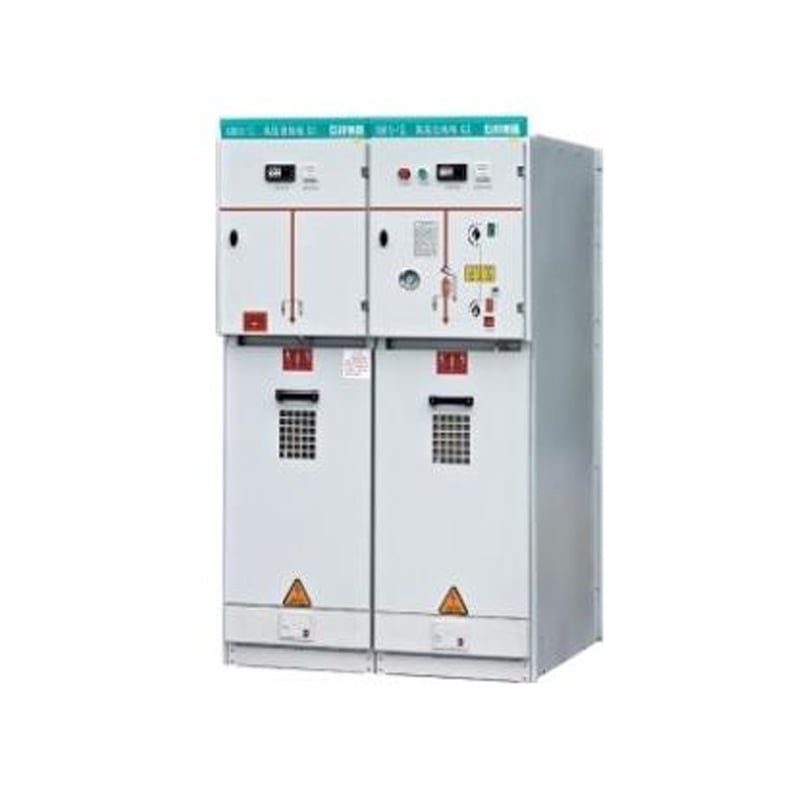
For a separately purchased collector panel, specify the feeder function, protection interfaces and cable termination.
View MV collection switchgear
For a transformer-only quotation, provide the converter operating duty, site conditions and required voltage pair.
View Oil-immersed transformers
Where a dry-type arrangement is being considered, include the enclosure or room ventilation and installation constraints.
View Dry-type transformersUse the same generation block and terminal names across the inverter data sheets, single-line diagram and equipment schedule.
Unit count, AC voltage, operating apparent power, reactive-power requirement and relevant operating limits.
Single-line diagram, collector voltage, feeder schedule, protection and metering points, and grid requirements supplied by the project.
Owner-furnished items, station footprint, cable entry routes, environmental conditions and responsibility for external works.
Use the same terminal labels in every quotation. An included outgoing panel still leaves the external cable, termination kits and site work to be assigned.
| AC interface | What the EPC should identify | What to assign in the quotation |
|---|---|---|
| Inverter AC connection | Show each inverter or PCS AC voltage, unit count, operating power and connection point. Identify the LV link and the party responsible for each end. | Ask who supplies the LV incoming equipment and links, who provides cable terminations and which items are owner-furnished. |
| Step-up transformer and station | Mark the LV and MV terminals, required voltage pair, transformer duty, auxiliary loads and the enclosure boundary. | Request separate entries for the transformer, LV panel, MV switchgear, auxiliaries, enclosure and internal connections. Identify equipment purchased outside the package. |
| MV collector feeder | Mark the feeder name, collector voltage, termination point, protection and metering interfaces on the single-line diagram. | Identify the supplier of the outgoing panel, external cable and termination kits. Ask who installs, terminates and tests the field connection. |