Request a Quote
Share the equipment and project requirements. If you need help selecting a model, describe the application.
Have drawings or specifications? Email [email protected] with your project reference.


Outdoor vacuum circuit breakers, disconnectors and current and voltage transformers for protection, isolation and measurement. Share your electrical ratings, installation conditions and drawings for a configuration review.
Start with the circuit function. Review each device’s ratings, installation arrangement and connections within its product family.
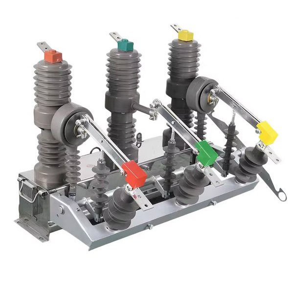
Outdoor switching and fault interruption. Compare the ZW32-12, ZW32-24 and ZW7-40.5 series for the specified duty.
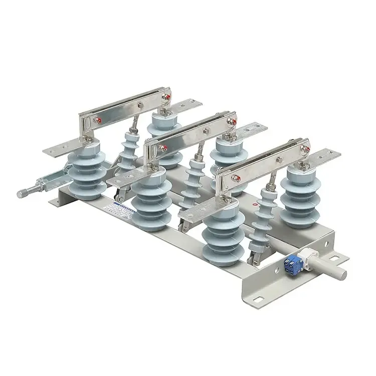
Isolation points for indoor and outdoor installations. Review the mounting, operating sequence and earthing requirements.
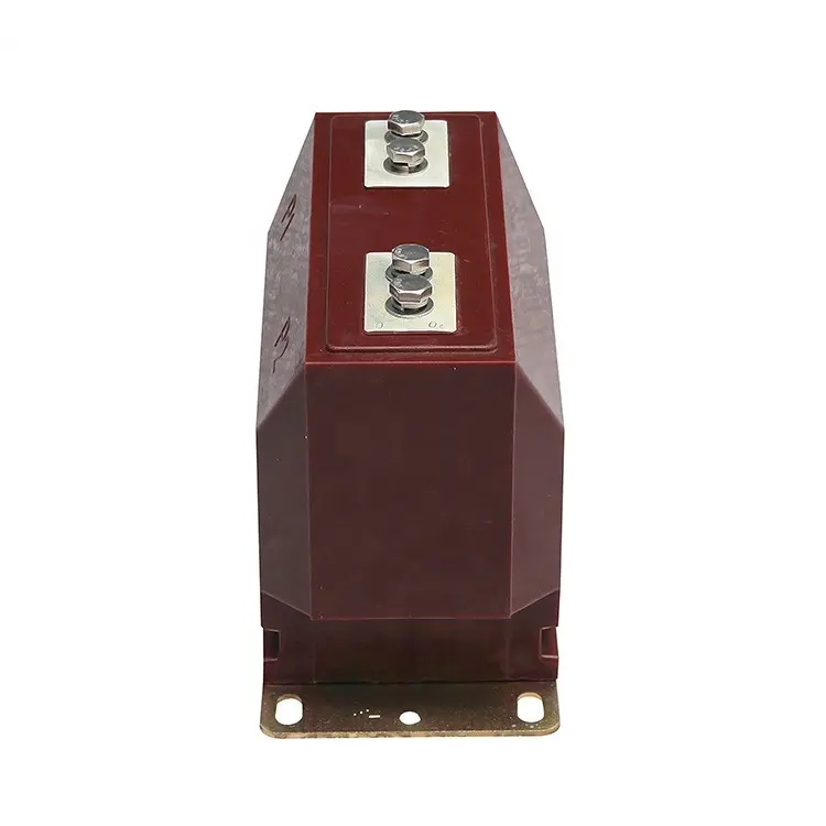
CT and VT signals for metering and protection. Specify ratio, accuracy, burden and secondary connections.
Switching and fault-clearing duty
An isolation point in the operating scheme
Current or voltage inputs to meters and protection
Mark each device’s location and function on the single-line diagram, including its connections to the protection and metering circuits.
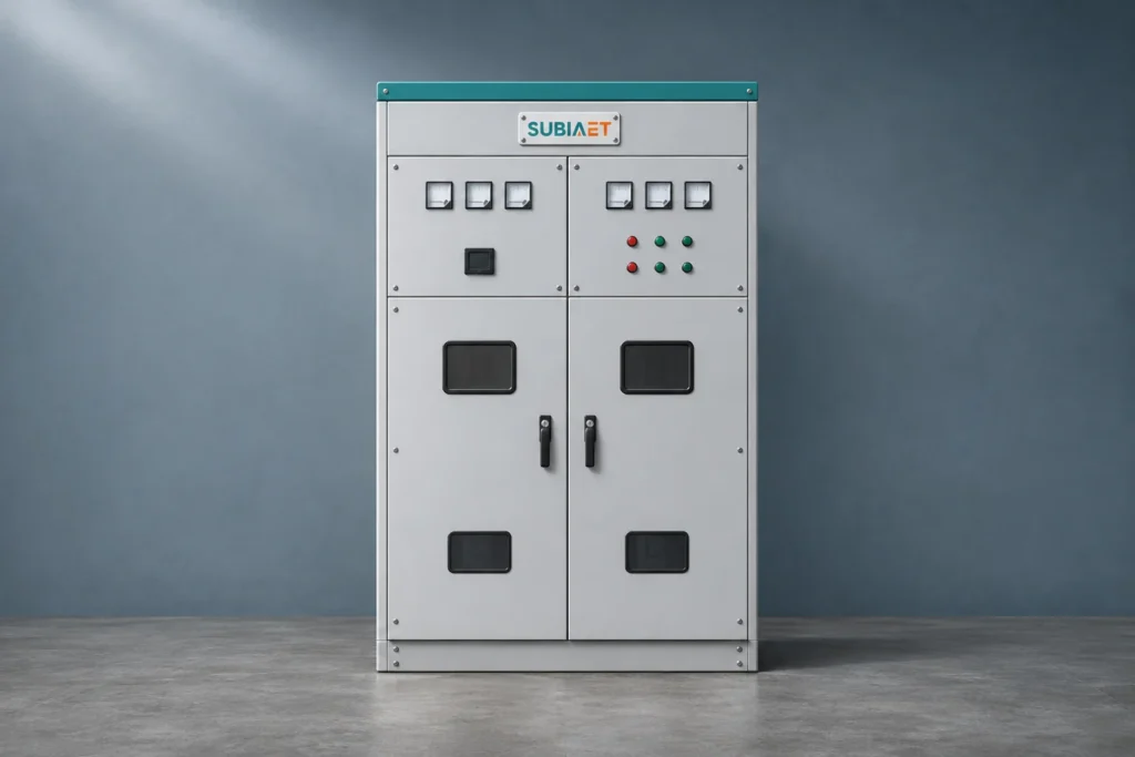
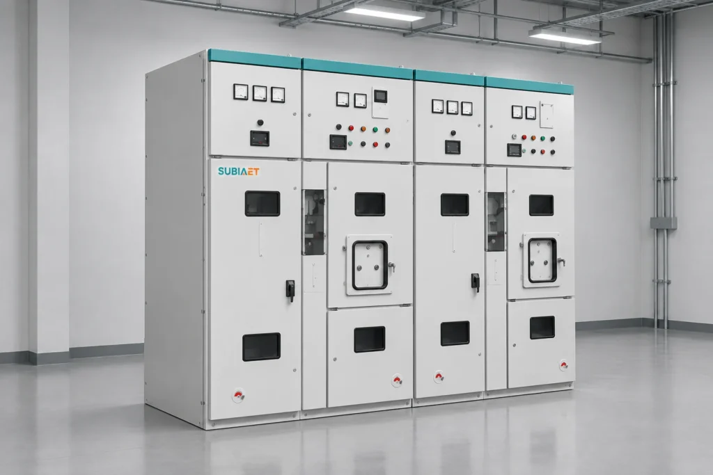
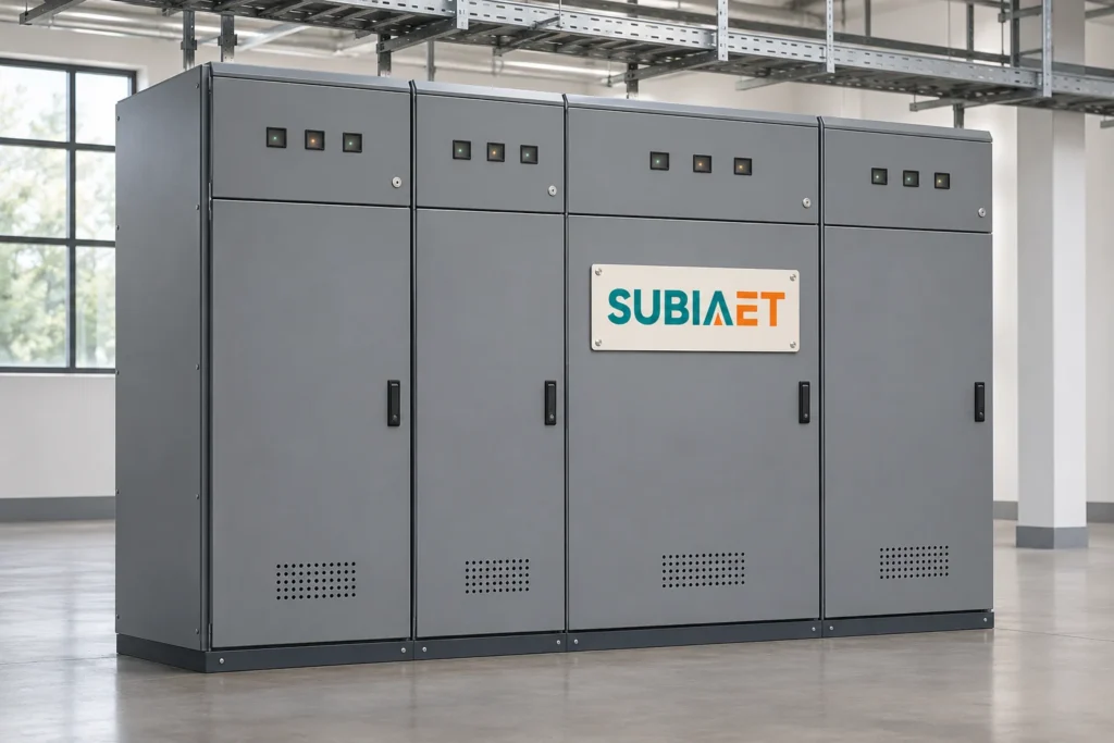
For a complete assembly, review the component requirements together with the panel arrangement, protection scheme and equipment supplied by others.
Explore MV & LV SwitchgearExplore Prefabricated Substations
Review overhead-feeder switching, fault interruption and isolation points against the utility scheme. Specify mounting, control supply, protection connections and outdoor conditions for each device.
Explore application
Coordinate incoming protection, isolation and metering with the plant single-line diagram. Match the selected devices to the installation space, approved control scheme and maintenance arrangements.
Explore application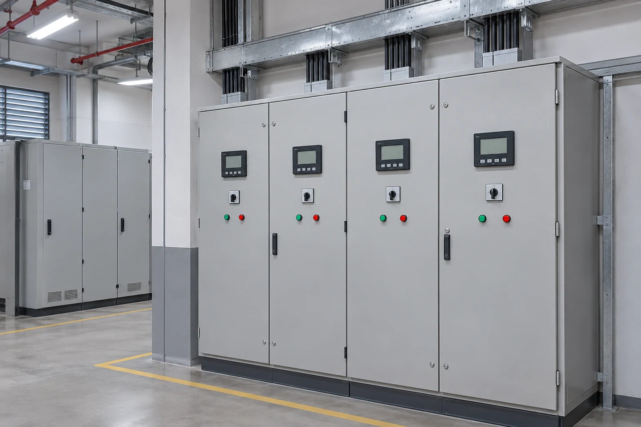
Define the current and voltage inputs required by meters and protection relays. Review CT/VT ratios, accuracy, burden, secondary wiring and indoor installation interfaces together.
Explore application
Start with the plant connection requirements and AC collection scheme. Confirm switching duty, isolation responsibilities, protection signals and the environmental conditions at each installation point.
Explore application
SUBIA reviews your circuit function, ratings and installation conditions to prepare the proposed equipment configuration.
Discuss mounting, primary connections, control supply and secondary terminals alongside the equipment and systems supplied by others.
Agree the drawing schedule and inspection records during technical review, matching the documents to the devices and ratings being supplied.
Review package markings, accessory lists and handling requirements so your team can plan receipt, storage and installation at the site.
Start with the circuit function. A circuit breaker provides the specified switching and fault-interruption duty; a disconnector provides an isolation point; a CT or VT supplies current or voltage signals for metering and protection. Use the single-line diagram to identify each device and its connections.
Do not assume a disconnector has load-break or circuit-breaker capability. Its isolation function must be coordinated with the appropriate switching device and operating sequence. Review any stated switching duty against the exact device specification before use.
Provide the system voltage, rated current, prospective fault current and required fault-duty values, frequency and operating sequence. Include control supply, protection connections, mounting and site conditions. Confirm the complete rating combination for the proposed model.
Identify CT or VT, the required ratio, secondary values, accuracy class, burden and metering or protection purpose. Include the wiring arrangement, terminal requirements, insulation level and available mounting space. Review current-transformer and voltage-transformer requirements separately.
State the installation location, ambient temperature, altitude, exposure and any contamination or condensation concerns. Provide mounting dimensions, connection details and operating access. Indoor devices require an installation arrangement suited to their specified service conditions.
Send the equipment list, quantities, single-line diagram, known electrical ratings and installation drawings. Add control or secondary-circuit requirements and identify items still to be confirmed. Agree the required drawings, inspection records, acceptance points and delivery documents during review.