Request a Quote
Share the equipment and project requirements. If you need help selecting a model, describe the application.
Have drawings or specifications? Email [email protected] with your project reference.

Separate primary and secondary circuits.
Dry-type and cast-resin constructions.
Open dry-type assemblies and SCB epoxy resin cast windings offer different construction arrangements. The electrical configuration, enclosure and cooling are specified for the installation.
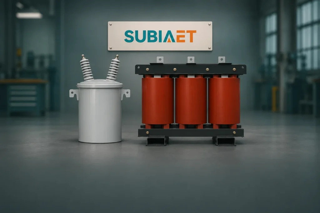
A core-and-winding assembly with separate primary and secondary circuits, upper connections and base-mounted cooling hardware.
Three-phase SCB10 / SCB11 / SCB13 constructions with vacuum-cast windings and optional temperature monitoring.
SUBIA’s isolation transformer range includes a dry-type assembly and an epoxy resin cast series. Both use separate primary and secondary winding circuits. Their construction, terminal arrangement and supporting equipment are presented as distinct product families.
The dry-type assembly places the winding and core arrangement, upper connections and base-mounted fans within one accessible structure. The epoxy-cast series uses resin-encapsulated windings with a silicon-steel core and steel supports, with winding-temperature monitoring available as an option.
Range applies to the SCB cast-resin family. Capacity, frequency, insulation and enclosure options are selected together for the ordered configuration.
In SCB13-1000/10, S identifies a three-phase transformer, C the cast-resin construction, and B the foil-winding designation. The 13 identifies the design series; 1000 and 10 identify the nominal kVA and primary-voltage class in this example.
SCB10, SCB11 and SCB13 name the cast-resin family. The full equipment specification also states secondary voltage, frequency, connection, cooling and accessories so the model code can be read alongside the actual project duty.

The dry-type product is illustrated as a three-column core and winding assembly. Connections are arranged above the windings, and fans are located along the base. This arrangement brings the winding assembly, connection points and cooling hardware into a single equipment envelope.
For integration into a cabinet or an equipment room, the useful interfaces are the mounting position, cable approach and access around the winding assembly. The installation layout should allow the terminal area and cooling hardware to be reached without obstructing the equipment’s airflow paths.
The upper connection area and the fan assemblies occupy different service zones. Cable entry, terminal access and the surrounding enclosure can be arranged around these zones while leaving the winding and cooling paths accessible.

The epoxy resin cast isolation family includes SCB10, SCB11 and SCB13 series designations. Its windings are cast and cured under vacuum, forming a solid resin insulation structure around the conductors. The construction combines a grain-oriented cold-rolled silicon-steel core with copper foil or copper conductors.
Steel clamps and supports position the core and winding assembly. A protective coating is applied to these structural parts. The result is an oil-free assembly for indoor installation, with the winding, core and supporting structure arranged for connection to the surrounding distribution equipment.
Capacity, voltage ratio and impedance are project configuration items. Enclosure protection and accessories are also selected for the installation, so the final equipment specification describes the complete assembly rather than relying on a series name alone.
Capacity and voltage ratio are specified for the selected configuration.
An isolation transformer transfers energy through the magnetic field in its core. The primary and secondary windings form separate conductive circuits, allowing the supply-side and load-side winding arrangements to be specified individually.
The voltage ratio is a separate design parameter: electrical isolation does not require a fixed 1:1 ratio. The installation design also establishes the secondary connection, earthing arrangement and protection. These system decisions remain relevant to the equipment connected to the transformer.
The secondary circuit is coordinated with the installation’s earthing and protective devices. A neutral connection, protective-earth connection and any screen earth have different roles; the connection drawing identifies each interface and the intended arrangement for the load.
Electrical isolation and interference attenuation describe different requirements. Separate winding circuits establish isolation. An electrostatic screen, when included in a transformer design, is an additional component between winding circuits and requires an appropriate grounding connection.
For sensitive equipment, an interference requirement should identify the noise type, frequency range and grounding arrangement. An attenuation value or a screened construction should appear in the agreed configuration before it is treated as a product performance characteristic.
Bring the supply connection, secondary load connection and equipment bonding into one interface drawing. If a screen is required, include its earth termination and the intended test conditions in that drawing; cable routing and the surrounding installation remain part of the interference assessment.
A useful transformer specification connects the electrical load to the physical installation. Capacity and the primary-to-secondary voltage ratio establish the basic duty; frequency, connection arrangement and impedance define further system requirements. Enclosure and mounting details then place that electrical design within the available space.
The connected load can affect the specification as well as the steady-state demand. Motor starting and other inrush conditions influence the permitted voltage drop. Where nonlinear loads are involved, their operating characteristics should be included in the load description so the transformer design can be assessed for the actual duty.
A numerical configuration brings capacity, voltage, connection and losses into the same specification. The example below is a published 1,000 kVA SCB13 configuration with a 10 kV primary and 400 V secondary at no load.
Its loss figures retain their stated temperature and operating conditions. For an order, the project data sheet connects the agreed performance to the chosen windings, cooling system, enclosure and duty.
| Item | Configuration |
|---|---|
| Rated capacity | 1,000 kVA |
| Primary / secondary | 10 kV / 400 V at no load |
| Frequency / connection | 50 Hz / Dyn11 |
| Cooling | AN — natural air |
| HV tapping range | ±2 × 2.5% |
| No-load loss | 1,275 W |
| Load loss at 120°C | 7,315 W |
| Impedance | 6% |
| No-load current | 0.3% |
Schneider Electric Trihal NX1/SCB13 catalogue reference, 2018, p.69; AN cooling is specified on p.18. Values describe this reference configuration and are not SUBIA guaranteed ratings.
10 kV primary; 400 V secondary at no load; 50 Hz; Dyn11; AN; HV taps ±2 × 2.5%; maximum ambient 40°C. Load loss is stated at a 120°C reference temperature.
The selected SUBIA equipment requires its own agreed electrical data and outline drawing. This table does not assign ratings to the gallery photographs.

The dry-type and cast-resin examples use air around the winding assembly to remove heat. Their base-mounted fans are visible construction features. The specified cooling designation establishes whether the selected rating uses natural air, forced air, or separate ratings for each operating condition.
The SCB range includes AN and AN/AF arrangements. Fan control, auxiliary power and access for inspection belong with the chosen arrangement. A fan-equipped photograph alone does not establish an increased kVA rating or a permissible overload duration.
Room temperature, enclosure ventilation and nearby equipment affect the available cooling air. Keep cable routes and surrounding construction clear of the intended air paths, and coordinate the room ventilation with the transformer’s actual losses and operating load.
| Item | Configuration |
|---|---|
| Cooling mode | AN or AN/AF for the selected SCB configuration |
| Available cooling air | Room ambient, intake and exhaust arrangement |
| Load duty | Continuous load, peaks, starting events and nonlinear equipment |
| Fan interfaces | Auxiliary supply, control and service access |
| Enclosure | Protection requirement coordinated with ventilation |
Winding-temperature monitoring is available for the epoxy-cast series. The system tracks winding temperature and can provide overtemperature alarm and trip functions. These are distinct functions: indication presents the measured condition, an alarm signals that attention is required, and a trip output interfaces with the project’s protective switching arrangement.
The selected monitoring equipment and its control interfaces belong in the project specification. Alarm and trip thresholds, supply requirements and connection details are established for that configuration.
Establish the equipment envelope before finalising the room or panel layout. The base, mounting points, lifting route and access opening need to accommodate the assembled transformer and the agreed enclosure, with space to reach the connection area during installation and servicing.
The product examples show exposed terminals and winding assemblies. An indoor installation therefore brings the transformer and the surrounding protective arrangement together: enclosure access, separation from adjacent equipment, ventilation and cable entry are considered as one layout.
Terminal position and cable approach influence the installation as much as overall dimensions. The final arrangement drawing identifies primary and secondary terminals, the earth connection, control wiring and service access. It also provides the mounting and handling information for the selected unit.
| Item | Configuration |
|---|---|
| Equipment envelope | Transformer, enclosure and terminal access |
| Support and handling | Mounting pattern, load-bearing support and delivery route |
| Power connections | Cable approach, termination space and circuit identification |
| Control connections | Fan supply and specified temperature-system interfaces |
| Service access | Winding, terminal and fan inspection access |
The epoxy-cast isolation series is used in building distribution and indoor facility applications. Applications include commercial buildings, rail transit facilities and precision laboratories. Its oil-free winding insulation and configurable electrical interfaces support an installation brief centred on the connected equipment and the indoor environment.

Coordinate transformer circuits with building switchgear, ventilation and service access. The electrical schedule defines the voltage ratio and the isolation arrangement for each installation.

Integrate the transformer with the equipment supply and control requirements. Connection arrangements, load characteristics and installation space are specified together.

Coordinate instrument supply circuits with the laboratory electrical design. The required isolation, earthing and interference-control arrangements follow the equipment and project specification.
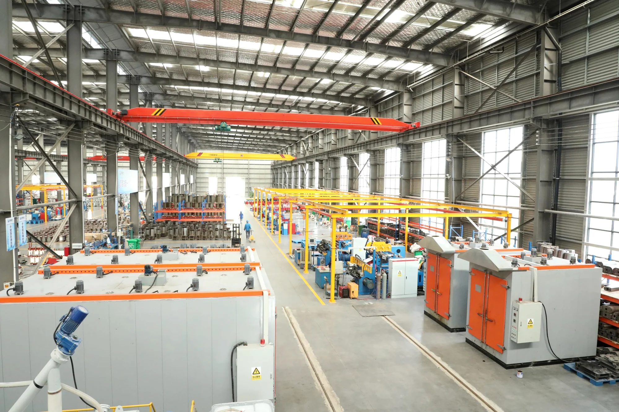
Illustrative application environments.
Equipment integration should account for terminal access, the enclosure arrangement and temperature-monitoring interfaces where specified. A project serving a specialised installation also needs the applicable system requirements to be included in its technical specification.
Industrial equipment integration combines the required supply conversion and separate winding circuits with the machine or process connection arrangement. For laboratories and other sensitive loads, specify any screen or interference requirement alongside the load duty, earthing and enclosure arrangement.
Subian’s published Zimbabwe project account describes an isolation transformer used between a 690 V supply and equipment requiring 400 V. It illustrates a practical integration duty: bringing a different equipment voltage into an industrial power system while keeping separate winding circuits.
For a similar installation, the load schedule and connection drawing establish the required kVA, duty and interfaces. The project account describes an application; the selected transformer’s rating and construction are defined in its own equipment specification.
| Item | Configuration |
|---|---|
| Location | Zimbabwe |
| Supply voltage | 690 V |
| Equipment voltage | 400 V |
| Function | Voltage conversion using an isolation transformer |
Published project example; not an electrical rating assignment for the photographed units.
The transformer specification connects the supply, connected equipment and indoor environment. Define the load duty together with the intended secondary earthing, enclosure and cooling arrangement.
Temperature, altitude, contamination and available access affect the complete installation. Include these conditions with the electrical requirements so the selected configuration fits both the network and its location.
Electrical duty
Capacity, primary/secondary voltages, frequency and load profileDesign reviewWinding configuration, rating and voltage regulation
Secondary system
Connection, neutral requirement and protective arrangementDesign reviewTerminals, earthing and system coordination
Thermal environment
Ambient temperature, altitude and room ventilationDesign reviewCooling arrangement and thermal design
Contamination
Dust, moisture, condensation and corrosive exposureDesign reviewEnclosure, surface protection and inspection access
Sensitive equipment
Noise type, frequency range and any screening requirementDesign reviewScreen arrangement, earth connection and agreed performance test
Physical layout
Room or panel space, support, cable approach and service routeDesign reviewEquipment envelope, mounting and installation drawing
The Subian dry-type selection guide introduces indoor applications and the configuration topics used to prepare a project brief.
This two-page preliminary guide covers capacity, insulation class, enclosure, cooling, noise considerations and temperature monitoring. Detailed ratings and installation dimensions belong in the selected equipment’s technical data sheet and drawing.
The model details retain the construction information and the qualified SCB13 reference configuration. The published Zimbabwe project account provides a separate example of 690 V to 400 V voltage conversion.
How supply and load phase, voltage notation and the physical arrangement shape transformer selection.
A walkthrough of a teaching nameplate with a copy-and-verify checklist for transformer replacement and RFQs.

A six-case example compares connected charging load, proposed managed limits, degraded controls and future cabinet additions.