Request a Quote
Share the equipment and project requirements. If you need help selecting a model, describe the application.
Have drawings or specifications? Email [email protected] with your project reference.

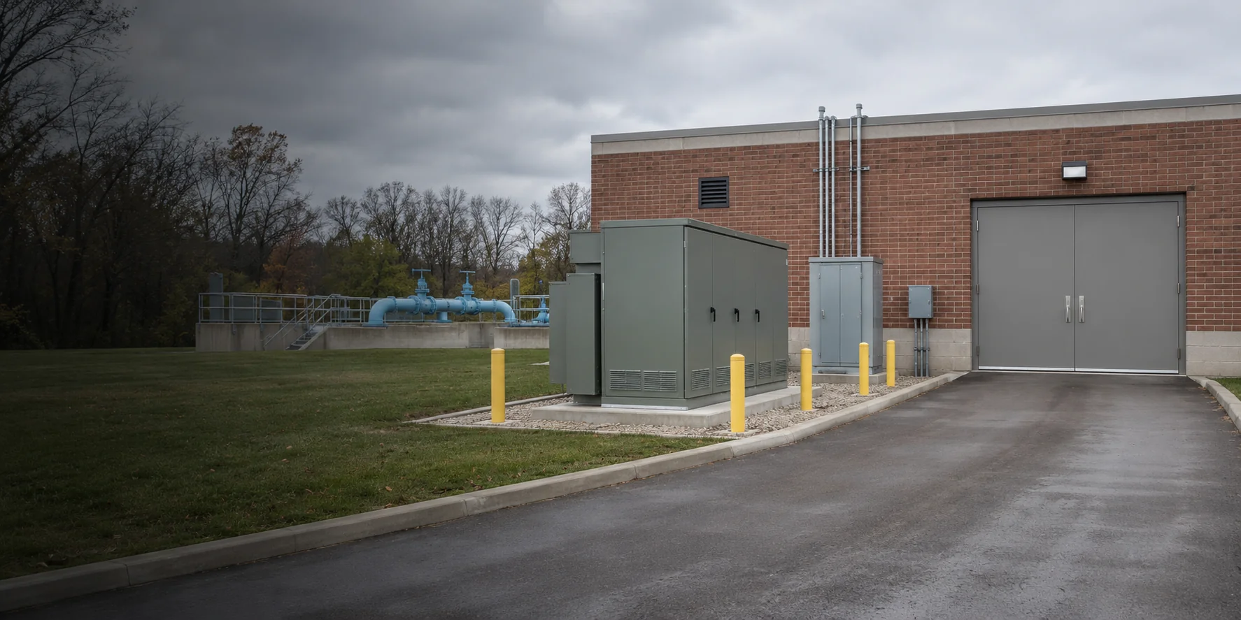
Charging depots, data centers, port terminals and water treatment plants draw power in different ways. Define the busiest operating period and the loads that must stay supplied before selecting transformers and switchgear.
A highway hub may see several vehicles arrive together. A bus or truck depot may charge most heavily between return and dispatch. Ask the operator for the busiest interval, the required turnaround time and the opening-day and future charger counts.
Suppose six dispensers share three cabinets drawing 200 kW AC each. With all three charging, the cabinets draw 600 kW. Add 120 kW of simultaneous building load. For balanced, sinusoidal loads at the same 0.90 lagging power factor, 720 kW ÷ 0.90 gives 800 kVA of steady demand. Check the actual input power factor, harmonics, site conditions and any enforceable import limit before choosing a transformer.
| Operating condition | Question to settle | What to request |
|---|---|---|
| Unmanaged peak | What will the site draw if all available cabinets run at full input? | Give the utility the cabinet count and AC input data, along with any existing loads on the same service. |
| Managed charging | What import limit has the operator agreed, and what happens if communications fail? | Ask the charger supplier to document the control limit and fallback behaviour before using a reduced demand in the quotation. |
| Fleet expansion | Will adding dispensers also add power cabinets? | Price the next feeder or transformer separately. Mark cable ducts, outgoing ways and space reserved for the additional cabinets. |
A new hall changes both rack demand and cooling demand. Give each bidder the initial and build-out loads, and show how the facility distributes power during normal operation and maintenance.
Suppose two paths each carry 500 kW of transferable load. If one is isolated and all of its load transfers, the surviving path carries 1,000 kW of that load. This example is a load transfer check. Add the cooling and auxiliary loads that also remain on that path, and account for UPS input losses when converting an IT output schedule to upstream demand.
| Operating condition | Question to settle | What to request |
|---|---|---|
| Normal operation | Which loads are on each UPS input and which cooling loads are supplied separately? | Request a per-path load schedule on one consistent side of the UPS, with cooling and auxiliaries listed separately. |
| Maintenance transfer | Which loads move, which can be shed, and which cooling plant must stay online? | Compare the bids at the same MV incomer and LV feeder to the UPS. Request the transformer, busbar and feeder duties during transfer. For separate equipment, price the transformer-to-board connection. For a packaged station, identify factory connections, site joints and tests. Mark cooling and bypass feeds separately. |
| Next data hall | How will the next hall connect while existing racks are in service? | Compare initial and ultimate board sections, reserved feeders and the shutdowns required for the connection. |
A port may need to serve a ferry while cranes and adjacent berths continue operating. Start with vessels and terminal loads that can draw power at the same time.
Two berths with similar vessel ratings can impose different shore-side loads if arrivals overlap or ships use different supply frequencies. Provide an occupancy schedule and the existing crane and terminal load. Mark shore switchgear, transformer, any frequency converter, cable-handling equipment and the ship connection as separate items.
| Operating condition | Question to settle | What to request |
|---|---|---|
| Concurrent calls | Which ships and terminal loads can operate together? | Ask for a berth-by-berth load schedule and the upstream duty for the busiest agreed overlap. |
| Ship connection | Which voltage and frequency does each vessel require, and who supplies the converter if needed? | Request a one-line with the converter, protection, metering and shore-to-ship connection boundaries identified. |
| Quay installation | Which berth must remain open while the next connection is built? | Compare cabinet access, cable routes, environmental exposure and staged tie-ins against the terminal operating plan. |
A reverse-osmosis train, intake pump and transfer pump have different starting and standby requirements. Identify which trains must remain available after a feeder outage.
Distinguish running pumps, standby units and motors that may restart together. For a pump station with utility MV supply and a contractor-supplied motor control panel, compare separate equipment and a packaged substation at the same terminals, from the incoming MV connection to the LV outgoing feeder.
| Operating condition | Question to settle | What to request |
|---|---|---|
| Steady production | Which intake, treatment and transfer pumps run together for the required water output? | Request coincident load by train. For separate transformers and switchboards, include the cable between them, lugs and installation when comparing costs. |
| Restart sequence | Which motors start across the line and which are controlled by drives? | Use motor and drive starting data for the same restart sequence in both bids. For a packaged station, confirm factory connections, joints between shipping sections and foundation work. |
| Standby operation | Which train or transfer duty remains available with one feeder isolated? | Show the alternate supply path. Assign the motor control panel, feeder cable, terminations at both ends, site tests and witnesses to named parties before comparing prices. |
Choose the installation setting and identify the opening, route or site condition that limits the equipment arrangement.
Use a plan to trace the route from the unloading point. Add a section where an overhead obstruction, a hatch or a change of level limits movement.

Record the narrowest clear opening, turning space and headroom from unloading to final position. Compare these with the supplier’s shipping section dimensions, handling mass and method of movement.
Show door swings, cable entries, service aisles and the space needed to remove the largest unit later. Identify routes that must remain available to staff, the public or other equipment.
Provide the ventilation arrangement and relevant temperature, noise or environmental limits. Request heat losses and clearances for the actual equipment so the building team can review the room design.
Show drainage and likely water exposure on the section. Ask for written confirmation for the proposed unit, terminations and accessories under those conditions before accepting it for the vault.

For indoor installations, compare shipping dimensions, heat losses and cable positions with the room drawings.
View Dry-type transformers
For an outdoor transformer purchase, identify the foundation, cable entry and operating access to the compartments.
View Pad-mounted transformers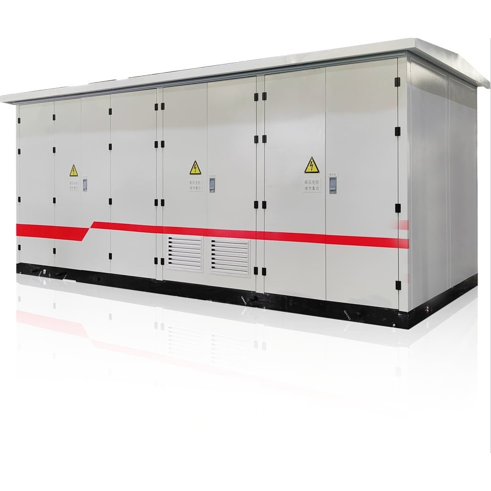
For a complete outdoor supply point, review the enclosure, transformer, switching equipment and external terminals together.
View Prefabricated substations
For a vault, review the proposed unit against the pit section, removal route, drainage and stated exposure.
View submersible distribution transformersSend the site plan and electrical single-line together. For charging projects include the maximum simultaneous AC demand. For data centers mark the critical loads and the supply path available during maintenance.
Delivery entrance, narrowest opening, lifting point, equipment footprint, maintenance and replacement route.
Single-line diagram, voltage pair, capacity or current, fault-level information and critical-service requirements.
Ventilation and noise requirements, drainage and water exposure where applicable, access restrictions and delivery sequence.
Give each bidder the same site drawings. Compare equipment, handling and civil interfaces against the same installation and removal route.
| Installation setting | What the site drawings should show | What to request in the quotation |
|---|---|---|
| Indoor switchroom | Show door openings, tight turns, headroom, cable entries, ventilation paths and maintenance space on the room plan and section. | Request shipping dimensions and mass, heat-loss data and the proposed maintenance clearances. Identify any sections that must be assembled on site. |
| Outdoor service yard | Mark the unloading position, foundation, cable approaches, door swings and lifting access. Show any public or service route that must remain open. | Compare a standalone transformer with a complete station for the same external terminals. Itemise the enclosure, switchgear, foundation interface and external cable work. |
| Underground equipment vault | Provide a vault section showing the clear hatch opening, lifting route, cable penetrations and drainage. State the anticipated water level and exposure duration. | Request a model-specific review of the transformer, terminals and accessories for the stated conditions. Identify lifting provisions, civil works and exclusions. |