Request a Quote
Share the equipment and project requirements. If you need help selecting a model, describe the application.
Have drawings or specifications? Email [email protected] with your project reference.

Compact outdoor distribution
with enclosed cable connections.
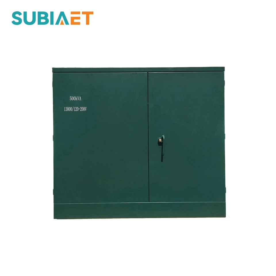
150, 500 and 1,000 kVA configurations for three-phase distribution. Series photographs illustrate enclosure designs; each technical panel identifies the electrical configuration.
150kVA
150 kVA ZGS enclosure views and a separate 13.8 kV / 208 V, Dyn11 configuration with ONAN cooling.
500kVA
500 kVA ZGS enclosure views and a separate 13.8 kV / 208 V, Dyn11 configuration with ONAN cooling.
1,000kVA
1,000 kVA ZGS enclosure views and a separate 13.8 kV / 208 V, Dyn11 configuration with ONAN cooling.
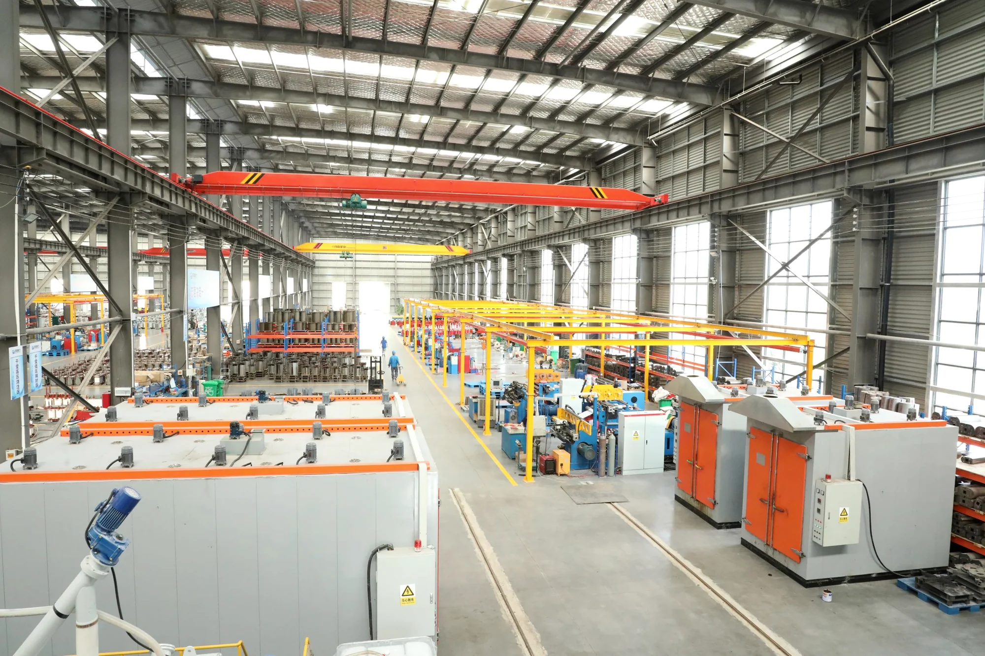
ZGS transformers combine the transformer active part, an HV load-switch and fuse arrangement, and an LV connection compartment in a compact pad-mounted unit. The three-phase series serves above-ground distribution points for residential communities, commercial sites and industrial facilities.
The ZGS family covers 50–2,500 kVA at series level. The electrical tables on this page describe separate 150 kVA, 500 kVA and 1,000 kVA designs at 13.8 kV / 208 V. Enclosure photographs show series examples; voltage ratio, winding connection and electrical values belong to the selected configuration.
| Property | Series scope |
|---|---|
| Series capacity range | 50–2,500 kVA |
| Transformer type | Three-phase, oil-immersed, pad-mounted |
| Cooling | ONAN — Oil Natural Air Natural |
| Active part | Copper windings and silicon-steel core |
| Installation | Outdoor, above-ground cabinet on a prepared foundation |
The series range is distinct from the three 13.8 kV configurations detailed below. It is not a complete rated model schedule.
The ZGS designation identifies a combined, common-tank, three-phase transformer. The following fields specify the rated capacity and the high- and low-voltage winding ratings.
In the 1,000 kVA configuration sheet, ZGS-1000-13.8/0.208 identifies the rated capacity and 13.8 kV / 208 V windings. The connection group, frequency and accessory arrangement complete the electrical and mechanical specification. A model label should be read together with its matching rated data.
| Code or field | Meaning |
|---|---|
| Z | Combined type |
| G | Common-tank enclosure |
| S | Three-phase |
| Capacity | Rated apparent power in kVA |
| HV / LV | Rated high- and low-voltage winding voltages |
The transformer core and windings operate in an oil-filled tank. Oil provides electrical insulation and transfers heat to the tank and cooling surfaces, where natural airflow removes it. ONAN operation uses this natural circulation arrangement without a forced-air fan system.
The cabinet houses the HV switching and connection arrangement together with the LV distribution interface. For the 13.8 kV configurations, the listed enclosure protection is IP54 and the construction uses copper windings and a silicon-steel core. The tank, cabinet doors and cable openings each have a role in the complete outdoor enclosure.
The front doors provide access to the connection area while the tank and external cooling surfaces sit behind it. Compartment access, cable-entry openings and terminal positions should be coordinated as one assembly. The front and open-door photographs illustrate this physical arrangement.

Two sets of primary connections for incoming and outgoing feeder cables.

One set of primary connections for an incoming feeder cable.
| Part | Function and construction |
|---|---|
| Transformer active part | Copper windings and silicon-steel core immersed in insulating oil |
| Oil tank | Contains the active part and insulating/cooling oil |
| HV arrangement | Load switch and fuse with the incoming cable interface |
| LV compartment | Outgoing low-voltage connections and distribution interface |
| Cooling arrangement | ONAN: natural oil circulation and natural airflow |
| Outdoor enclosure | IP54 specified for the three 13.8 kV configurations |
Radial feed and loop feed are available within the pad-mounted configuration. A radial arrangement terminates an incoming feeder at the transformer. A loop-feed arrangement provides incoming and outgoing HV cable positions so the transformer can form part of a feeder route.
The feed arrangement determines the cable-compartment layout and the switching scheme. A loop-capable enclosure does not by itself define how the utility operates the network: loop-feed equipment can also be installed on a radial system. Source selection and sectionalizing functions depend on the actual switches and single-line diagram.
Specify the incoming feeder, outgoing feeder where applicable, normal operating connection and required isolation points in the single-line diagram. These details establish the required cable positions and switch functions before terminal and protection components are selected.
The integrated HV arrangement includes a load switch and fuse protection. Switching establishes the operating connection of the transformer or feeder, while fusing forms part of the overcurrent-protection arrangement. These functions have to work with the upstream network protection and the downstream LV protective devices.
The single-line diagram brings the feed type, transformer connection and protection arrangement together. Switch function, fuse rating and cable termination are individual design selections; the kVA rating alone does not define them. Their coordination also depends on the available fault level and the operating requirements of the utility or facility.
The accessory schedule should name the selected switch and fuse arrangement together with the required ratings and connection interfaces. This keeps the physical compartment layout aligned with the protection study and the operating procedure for the installation.
| Engineering item | Relationship to the pad-mounted unit |
|---|---|
| HV load switch | Operating connection for the selected radial or loop-feed arrangement |
| Fuse protection | Transformer protection coordinated with the supply and LV protection |
| Primary cable termination | Voltage class and interface matched to the HV connection arrangement |
| LV protective devices | Coordination with transformer output, circuit demand and system fault level |
The HV and LV cable interfaces are arranged at the transformer compartments. The 13.8 kV configurations use a delta primary, so their winding connection is different from a grounded-wye primary design. On the secondary side, the star-point neutral supports the stated 208 V three-phase and 120 V phase-to-neutral supply.
Cable entry, terminal layout and the neutral connection are carried into the connection drawing. This drawing links the incoming MV feeder, outgoing LV circuits and earthing connections to the actual cabinet arrangement. Cable size, termination type and the number of parallel LV conductors affect the space required inside the compartments.
Identify the primary cable construction and termination interface, the outgoing phase and neutral conductors, and any required parallel cable runs before the terminal layout is finalized. The dimensions of the cable openings and the working space then follow the actual connections and approved installation drawing.
The three configurations use a delta-connected 13.8 kV primary and a star-connected 208 V secondary with an accessible neutral. The Dyn11 connection supports three-phase 208 V loads and 120 V phase-to-neutral service. The rated frequency is 60 Hz, with a separately selected 50 Hz design option.
Copper windings, a silicon-steel core and ONAN cooling are common to these configurations. Short-circuit impedance differs by capacity and forms part of the system fault-current and protection study. The detailed panels also include insulation levels, enclosure protection and the specified ambient-temperature range for each configuration.
The neutral is the star point of the low-voltage winding. A phase-to-neutral 120 V circuit is part of this three-phase secondary arrangement; it does not turn the transformer into a single-phase model. The load schedule and neutral requirements should accompany the single-line diagram.
| Rated capacity | Rated HV | Rated LV | Frequency | Vector group |
|---|---|---|---|---|
| 150 kVA | 13.8 kV, delta | 208 V line-to-line / 120 V line-to-neutral | 60 Hz; separate 50 Hz option | Dyn11 |
| 500 kVA | 13.8 kV, delta | 208 V line-to-line / 120 V line-to-neutral | 60 Hz; separate 50 Hz option | Dyn11 |
| 1,000 kVA | 13.8 kV, delta | 208 V line-to-line / 120 V line-to-neutral | 60 Hz; separate 50 Hz option | Dyn11 |
These are separate copper-wound, Dyn11 configurations. The 50 Hz option is a design choice; it does not change a 60 Hz nameplate rating in service.
Product images illustrate ZGS enclosure arrangements. They do not identify the exact voltage or winding configuration in this table.
The three 13.8 kV configuration sheets specify 34 kV power-frequency withstand on the high-voltage side and a 95 kV basic impulse level. The project insulation schedule should coordinate the transformer, primary cable interface and protective devices around the selected voltage and network arrangement.
Short-circuit impedance is 4.5% for the 150 kVA and 500 kVA configurations and 5.75% for the 1,000 kVA configuration. The respective no-load-current limits are 0.8%, 0.7% and 0.6%. Keep these values with their capacity, voltage ratio and Dyn11 connection when carrying out the network study.
Each technical panel also includes approximate loss data from its configuration sheet, with load loss referenced to 75 °C. These values support preliminary specification. The final loss guarantees, test conditions and acceptance documents are agreed for the ordered design; the 50 Hz option needs its own rated data.
| Rated capacity | Short-circuit impedance | No-load current |
|---|---|---|
| 150 kVA | 4.5% | ≤0.8% |
| 500 kVA | 4.5% | ≤0.7% |
| 1000 kVA | 5.75% | ≤0.6% |
Values apply to the 13.8 kV, Dyn11 configurations. They are not transferred to other voltage or winding arrangements.
| Electrical property | Specified value |
|---|---|
| HV power-frequency withstand | 34 kV |
| Basic impulse level | 95 kV |
Configuration-sheet values; the required tests and acceptance documentation follow the project specification.

ONAN cooling uses the natural circulation of insulating oil and surrounding air. Heat passes from the core and windings to the oil, then through the tank and cooling surfaces to the environment. The listed configurations do not require a forced-air fan system.
The three 13.8 kV technical sheets specify an ambient range of −40 °C to +40 °C and an IP54 outdoor enclosure. Cooling surfaces need airflow, and the siting design should account for nearby walls, equipment and vegetation. Any different ambient or elevation conditions belong in the project specification.
Enclosure requirements include the cabinet construction, exposed surfaces and cable entries. The listed IEEE C57.12.28 reference addresses pad-mounted enclosure integrity; it does not establish the transformer’s electrical rating or approve a different site environment. The required finish and acceptance documents follow the selected enclosure specification.
| Item | Specification or project input |
|---|---|
| Cooling | ONAN — natural oil circulation and natural airflow |
| Ambient temperature | −40 °C to +40 °C in the configuration sheets |
| Enclosure protection | IP54 in the configuration sheets |
| Airflow and access | Space around cooling surfaces and access to operating compartments |
| Exposure | Dust, coastal salt and corrosive conditions stated with the project requirements |
IP54 is an enclosure-protection specification, not a statement of suitability for immersion or flooding.
A prepared foundation supports the transformer and aligns its cable openings with the site cable route. The layout also leaves space for doors, cable terminations and operating access.
Earthing connects the enclosure to the site earthing system; neutral grounding follows the network design. The selected unit’s overall drawing defines its footprint, lifting points and mass, while the project design establishes anchoring and clearances.
Locate the transformer so that the cable route, door swing and operating approach remain usable after surrounding works are complete. Confirm handling access before delivery and use the approved lifting and foundation information for the ordered assembly.
| Interface | Design purpose |
|---|---|
| Foundation and anchoring | Support the unit and align its base with the cable route |
| HV and LV cable openings | Match the connection drawing and cable installation space |
| Tank and cabinet earthing | Integrate exposed metalwork with the site earthing system |
| Operating access | Keep doors, switching positions and terminations accessible |
| Lifting and handling | Use the unit-specific drawing, lifting points and mass |
Clearances, anchoring and earthing details follow the project design and the local utility requirements.
ZGS transformers serve outdoor distribution points where the transformer and connection compartments need to occupy one compact location. Residential and commercial installations use the unit to connect a medium-voltage feeder to local low-voltage distribution. Industrial installations use the same arrangement to supply factory or plant loads.

Place enclosed distribution equipment along the community service network, with underground cable entry and a clear maintenance area around the cabinet.

Coordinate the transformer position with building loads, service roads and landscaped areas. Cabinet access remains separate from routine pedestrian and vehicle movement.

Locate distribution equipment near plant loads while allowing room for cable routing, cabinet access and maintenance vehicles. The site layout defines the required protective measures.
Illustrative application environments.
The 208 V / 120 V configurations are relevant when those voltages match the load schedule. A 13.8 kV primary, Dyn11 winding connection and the selected feed arrangement must also match the supply network. Capacity selection follows the connected load, operating demand and the project load plan.
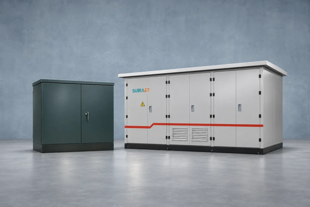
Follow the same three LV feeders through two example quotations and see which equipment and interfaces each package covers.

Separate the primary feeder path from the termination type and compare transformer offers against the actual project interface.
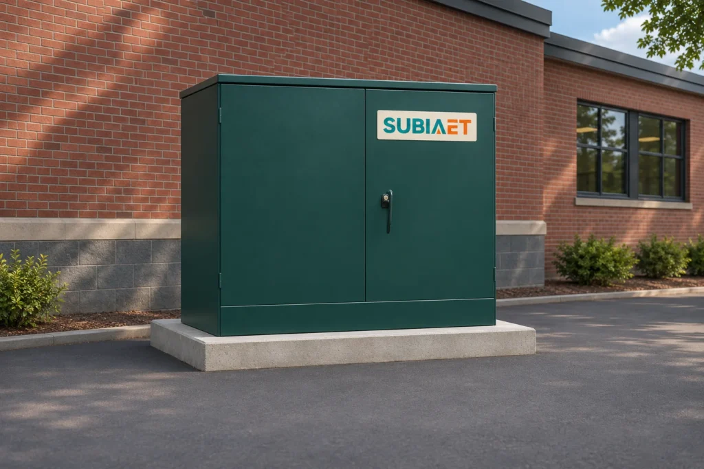
A guide to the ground-level cabinet, underground cable approach, compartment layout and typical uses.