Request a Quote
Share the equipment and project requirements. If you need help selecting a model, describe the application.
Have drawings or specifications? Email [email protected] with your project reference.

Pole-mounted oil-immersed transformers.
Power for local distribution.
A single-phase oil-immersed construction for individual services and engineered three-unit banks. Capacity, voltage and terminal arrangement are specified for the network.
D SERIES
Oil-immersed pole-mounted transformers for individual single-phase services and engineered three-unit banks.
The single-phase pole-mounted supply range covers 10–333 kVA, with primary-voltage options from 4,160 to 34,600 V and secondary options of 120/240 V or 240/480 V. These transformers step down the distribution voltage close to the load, serving homes, farms, small commercial premises and single-phase utility feeders.
The primary rating must match the voltage applied across the transformer winding. The selected secondary arrangement then determines the voltage available to the connected service. Capacity and voltage are specified together for each unit.
Voltage entries describe series options. The nameplate and connection drawing define the selected capacity, winding voltages and terminal arrangement.
In the D11-O-25/12.47 designation example, D identifies a single-phase transformer, 11 is the loss-efficiency series code and O identifies the overhead arrangement. The final fields represent rated capacity in kVA and the high-voltage rating in kV.
This example explains the model format. The selected transformer needs its complete voltage combination, frequency, tapping arrangement and connection drawing in addition to the short model code.

The D series uses a grain-oriented silicon-steel core and insulated copper conductors. The core carries the alternating magnetic flux, while the winding arrangement establishes the voltage ratio. Insulation between conductors, windings and the grounded tank supports the electrical separation required by the design.
The welded steel tank houses the active assembly and insulating oil. The oil provides electrical insulation and transfers heat away from the windings. An external corrosion-protection coating and gasketed joints form part of the outdoor construction.
| Part | Construction and installation detail |
|---|---|
| Magnetic core | Grain-oriented, cold-rolled silicon steel. Provides the magnetic path for voltage transformation. |
| Windings | Insulated copper conductors. Carries load current in the primary and secondary circuits. |
| Tank | Welded steel construction. Houses the active assembly and insulating oil. |
| External finish | Anti-corrosion coating. Protects the exposed steel surface. |
| Sealing | Ageing-resistant rubber gaskets. Seals tank joints and equipment interfaces. |
Oil carries heat from the windings toward the tank, where it is released to the surrounding air. The continuous load, daily peak and ambient conditions belong to the same rating assessment; the tank and mounting position need adequate space around the cooling surfaces.
Specify the system frequency and required temperature-rise basis with the kVA rating. A duty with sustained high demand or repeated load peaks requires a defined thermal assessment; a higher short-duration demand is not automatically an available overload rating.
| Item | Configuration |
|---|---|
| Load profile | Continuous demand, daily peaks and expected future load |
| Frequency | State the actual system frequency for the winding design |
| Ambient conditions | Minimum and maximum temperature, altitude and exposure |
| Cooling space | Tank clearance and unobstructed airflow at the pole assembly |
High-voltage bushings connect the primary winding to the incoming distribution circuit. Low-voltage terminals connect the secondary winding to the service conductors. The tank earth connection belongs to the installation grounding system and must be coordinated with the network neutral arrangement.
Pole-mounted transformers may have different bushing layouts. The illustrated D-series configurations include both one and two top-bushing arrangements. Select the layout from the required winding and network connection, then use the unit’s terminal markings and nameplate diagram for installation.

| Interface | Construction and installation detail |
|---|---|
| Primary bushings | Connection to the incoming distribution circuit. Primary winding voltage and terminal identification. |
| Secondary terminals | Connection to the low-voltage service. Selected 120/240 V or 240/480 V arrangement and neutral, where applicable. |
| Tank earth | Connection of the metal tank to the grounding system. Earthing point and the specified bonding arrangement. |
| Tap selector, where fitted | Adjusts the winding ratio within the specified tap range. Tap positions and the selected operating position. |
Changes to non-loadbreak tap settings require the transformer to be de-energized.
A D-series transformer can supply a single-phase load independently. It can be mounted on a wooden or concrete utility pole, with the mounting arrangement matched to the pole structure and transformer weight. This places the transformation point within an overhead distribution network.
Three single-phase transformers can also form an engineered three-phase bank. The bank connection establishes how the individual windings work together and which system voltages and neutral arrangement are available. Each transformer remains a separate single-phase unit; the bank requires a coordinated connection design.
| Arrangement | Construction and installation detail |
|---|---|
| Individual unit | Supplies a single-phase load or service. Pole support, terminal orientation and the service connection. |
| Three-unit bank | Combines three single-phase units to supply a three-phase load. Bank wiring, winding compatibility and the required system neutral. |
| Grouped pole installation | Positions multiple units on the supporting pole structure. Mechanical support, conductor routes and access to each unit. |
Use the approved bank diagram for a three-unit installation; a product photograph is not a wiring diagram.
Coordinate overcurrent and surge protection with the feeder and the transformer connection. A conventional pole unit and a completely self-protected arrangement have different protective-device packages; the required package should be named in the equipment schedule.
Primary fusing, surge arresters and any secondary breaker serve different functions. Their ratings and locations depend on the system and protection study. Pressure-relief devices, tap controls and other service accessories are included only where specified for the selected unit.
The gallery does not establish a complete self-protected equipment package. Confirm the fitted devices on the order drawing.
The Technical data tab includes a published CNC Power D11 reference matrix covering 10–333 kVA. It separates no-load and load losses by capacity, giving a numerical starting point for an engineering discussion.
The source does not state frequency or load-loss reference temperature. These values are not SUBIA guaranteed ratings and do not identify the photographed 37.5 kVA unit. Specify the required loss basis with the chosen voltage and winding configuration.
| Item | Configuration |
|---|---|
| No-load loss | State the applicable rated voltage and frequency |
| Load loss | State rated current and the reference temperature |
| Delivered configuration | Match capacity, voltage, tapping and connection to the agreed data sheet |
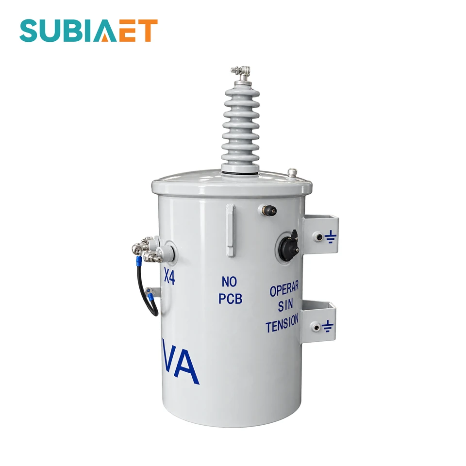
The primary and secondary voltage selections define the electrical starting point. Tap arrangements, bushing positions and mounting details then adapt the transformer to the service connection. These choices are resolved together so that the electrical schedule and pole drawing describe the same installation.
Outdoor finish, identification and packing can be specified for the project. The final equipment schedule should state the selected rating and accessories explicitly; the overall series range does not prescribe every capacity-and-voltage combination.
| Item | Configuration scope |
|---|---|
| Capacity and voltage ratio | Select the rated kVA and the required primary and secondary winding voltages |
| Tap arrangement | Specify the tap range and positions for the selected winding design |
| Bushings and terminals | Coordinate terminal locations and connections with the incoming line and outgoing service |
| Pole mounting | Coordinate mounting details with the pole or bank structure |
| Outdoor finish | Specify the coating requirement for the installation environment |
| Identification and packing | Custom labeling and packing for the agreed order |
The D series serves local loads along an overhead distribution network. Typical settings include residential neighbourhoods, farms and villages, and small commercial premises.

For local residential supply, specify the service voltage, diversified load and utility connection requirements.

For dispersed homes and rural service points, coordinate transformer capacity with feeder conditions and the required low-voltage supply.

For small shops and offices, confirm connected load, peak demand and the specified service voltage.
Illustrative application environments.
Place the transformer rating in the context of the service demand and voltage at each location. An individual unit supplies a single-phase service; an engineered bank is a separate connection arrangement for an appropriate three-phase load.
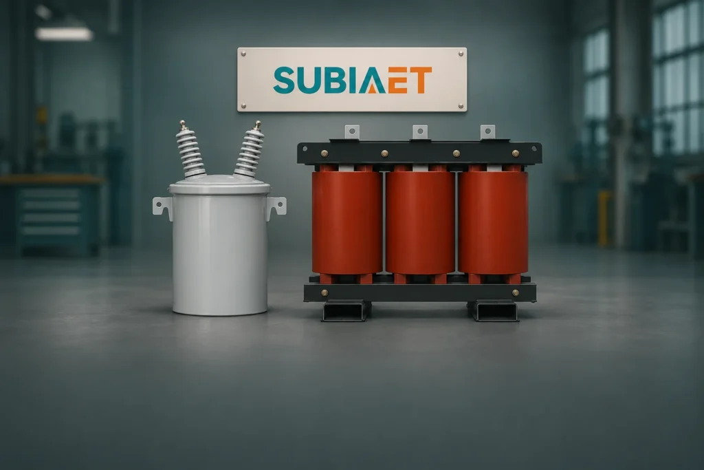
How supply and load phase, voltage notation and the physical arrangement shape transformer selection.

A worked A/B example compares normal, transfer, bypass and recovery loads before shortlisting transformer ratings.

A six-case example compares connected charging load, proposed managed limits, degraded controls and future cabinet additions.