Request a Quote
Share the equipment and project requirements. If you need help selecting a model, describe the application.
Have drawings or specifications? Email [email protected] with your project reference.

S-MD series for underground vault installations.
A sealed tank, external radiators and top-mounted connections form an assembly configured around the electrical duty and underground installation.
S-MD
The S-MD uses separable plug-in cable connectors on the high-voltage side. It also features a sealed oil tank with a welded cover, a C5-M anti-corrosion coating and a design for low temperature rise.
The S-MD series is intended for distribution equipment installed in underground pits. It brings the transformer below ground level where surface space is needed for roads, landscaping or other site uses. The electrical rating, voltage ratio and cooling arrangement are configured around the connected distribution system and the conditions inside the pit.
An underground installation combines an electrical product with a civil enclosure. The transformer tank, radiator panels, terminal area and service fittings therefore need to be considered together with the access opening, cable routes, drainage and heat-removal paths.
| Item | Series information |
|---|---|
| Electrical configuration | Capacity and voltage ratio configured for the distribution duty |
| Thermal arrangement | Cooling scheme coordinated with the pit environment |
| Product designation | S-MD submersible distribution transformer series |
| Installation | Below-ground equipment pit |
| Equipment arrangement | Main tank with external radiator panels and top-mounted terminals |
| Access | Lifting, cable connection and service access incorporated into the pit layout |
| Application contexts | Urban distribution, road lighting, landscaped sites, underground parking and low-lying sites |

The illustrated unit has a central tank, radiator panels along its sides and terminals positioned above the tank. The different views show the relationship between the tank body, the cooling surfaces and the connection area, helping project teams assess the arrangement required within a below-ground enclosure.
The 500 kVA example carries the voltage marking 12470(4800)/120–208V. Capacity and voltage ratio for a new installation are configured around its supply system and connected load.
A separate 150 kVA example shows the side profile of the tank and radiators. These equipment views help coordinate the tank envelope, top connections and service access with the pit layout.
| Marking | Text on the unit |
|---|---|
| Capacity | 500kVA |
| Voltage | 12470(4800)/120–208V |
The voltage marking is reproduced as printed. The parenthetical value is not presented as a tap position or a separate selectable rating. These markings identify the 500 kVA example shown in the product gallery.
| View | Visible marking |
|---|---|
| Left-side equipment view | 150kVA |
This capacity marking belongs to the left-side example. It does not identify every image in the gallery or establish a series capacity range.

The sealed S-MD oil tank has a cover welded to the tank body and a C5-M protective coating on the exterior. The pictured unit has side-mounted radiator panels and an upper terminal area.
The radiators provide additional heat-transfer surface outside the main tank. Their projection and the position of the terminals determine the equipment envelope used for the pit and cable-interface design.
For a wet underground location, the enclosure boundary includes the tank cover, joints, terminal penetrations and every fitted service accessory. Specify these interfaces together with the water duty so the assembled equipment and the connected cable system can be assessed as one installation.
The photographed S-MD examples place their electrical terminals on the upper part of the tank. This arrangement brings the cable interfaces close to the pit opening, while the radiator panels occupy the sides. The final connection drawing needs to establish cable approach, terminal identification and room for each cable bend.
The high-voltage plug-in cable connector encloses the electrical contact and seals against its matching bushing when correctly fitted. Specify compatible connectors and seals for unused connection points based on the expected water exposure and the height of the terminals.
The electrical schedule should identify primary and secondary voltages, frequency, winding connection and the earthing arrangement. Coordinate conductor material, cable size, parallel runs and terminal hardware with the outgoing circuits. Switching, surge protection and fault-protection interfaces should be shown on the project single-line diagram.
| Interface | Information to coordinate |
|---|---|
| Supply and outgoing circuits | Primary and secondary voltage, frequency, winding connection and load schedule |
| Terminal arrangement | Connection positions, conductor material, cable size and parallel cable runs |
| Cable sealing | Cable and connector combination, sealed unused positions and the applicable water exposure |
| Earthing and protection | Tank bonding, system neutral/earthing arrangement and the single-line protection scheme |
These are project configuration inputs. The photographed terminal arrangement does not establish a connector rating or a switching/protection package.
Rainwater and floodwater exposure can influence a below-ground installation. The relevant duty includes the water level, duration of exposure and whether the transformer must remain energised. These conditions apply to the complete installation, including its cable terminations and accessories.
An immersion designation needs defined conditions. For IPX8 assessment, the manufacturer and user agree the immersion conditions; the designation alone does not supply a universal depth or duration. The project specification should connect its required water exposure to the proposed equipment assembly.
For temporary flooding, specify the maximum water level, the longest expected event and the time available to drain the pit. For continuous immersion, state that duty explicitly, together with the required load and the operating period. Continued energised operation and post-flood return to service are separate requirements in the project operating plan.
| Condition | Engineering significance |
|---|---|
| Water level | Defines the parts of the tank, terminations and accessories that may be covered. |
| Exposure duration | Distinguishes a temporary flooding event from continuous immersion duty. |
| Operating state | Identifies whether the required duty includes energised operation during exposure. |
| Water characteristics | Fresh water, contaminated floodwater and saline water present different material and corrosion conditions. |
| Assembly boundary | Includes cable entries, connectors, covers, service fittings and installed accessories. |
| Verification scope | Connects the agreed duty to the exact equipment assembly and applicable test documentation. |
State water depth relative to a defined reference point on the equipment, such as the tank base or highest exposed connection. Include maximum level, exposure time and energised/de-energised state in the agreed technical schedule.
An IPX8 designation describes an ingress-protection test under agreed conditions. It does not by itself establish a transformer load rating, an unlimited operating period or suitability for every water chemistry.

Transformer losses become heat that must pass from the active assembly to the external cooling surfaces and then into the surrounding environment. Below ground, the pit encloses those surfaces and changes the conditions for heat removal.
The S-MD is designed for low temperature rise, with a cooling scheme matched to the installation. The rated load, ambient conditions inside the enclosure, available heat-removal paths and expected water exposure are considered together. The pit cover, cable routes and civil structure must preserve the resulting thermal arrangement.
Consider the normal dry-pit condition and the specified flood condition separately. The pit inlet and outlet paths, cover arrangement and deposits around the radiators can change heat removal. Specify the continuous and peak load profile, enclosure temperature and ventilation arrangement before assigning the operating duty.
| Input | Effect on the installation |
|---|---|
| Load profile | Continuous demand, peak duration and expected load growth define the heat to be removed. |
| Pit ambient | Temperature around the tank and radiators is the relevant enclosure condition. |
| Heat-removal path | Pit volume, cover openings, ventilation and radiator clearance determine the available arrangement. |
| Flooded condition | Water level, duration, contamination and operating load form a separate specified duty. |
A workable installation provides a continuous route from delivery to positioning, cable connection and later servicing. The access opening needs to accommodate the final equipment envelope and lifting arrangement. The supporting structure and cable routes then follow the actual outline and terminal drawings.
Drainage, cable access and maintenance space are separate parts of the same layout. Organising them together reduces the chance that a pipe, cable support or cover obstructs a service fitting or cooling surface.
| Interface | Design coordination |
|---|---|
| Entry and removal | Access opening and lifting route for the assembled equipment. |
| Support | Foundation arrangement and load-bearing points matched to the final outline drawing. |
| Cable route | Cable direction, termination position and cable movement kept clear of service access. |
| Heat removal | Air paths and the surrounding enclosure considered together with external radiator surfaces. |
| Drainage | Water collection and removal coordinated with the expected site exposure. |
| Maintenance | Access to terminals, fittings and radiator surfaces retained after cables and covers are fitted. |
S-MD applications include urban underground distribution, road lighting, landscaped sites and underground parking. These uses share a practical requirement: accommodating distribution equipment while keeping surface space available for the surrounding development.
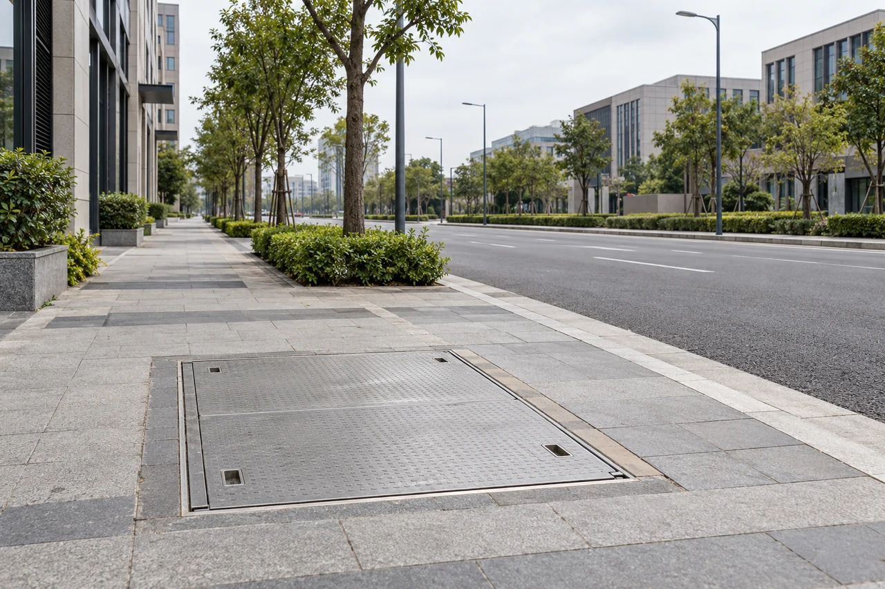
Keep surface space available for roads and street lighting while coordinating underground distribution equipment with access openings, cable routes and drainage.

Integrate below-ground equipment into the service edge of a park or plaza. Coordinate the access opening with paving, planting and clear routes for maintenance.

Coordinate equipment access and cable routes with the parking layout, keeping service space clear of vehicle circulation and routine pedestrian movement.
Illustrative application environments.
Low-lying locations add water exposure to the installation brief. The electrical configuration and the pit design need to reflect the actual site duty, including access, drainage and the conditions expected during a flooding event.
Subian’s published Venezuela reference describes a utility delivery that included pad-mounted and submersible transformers. The reported scope covered configuration review, production coordination, unit identification, pre-shipment inspection and export packing.
The reference illustrates the coordination involved in supplying equipment for a distribution project.
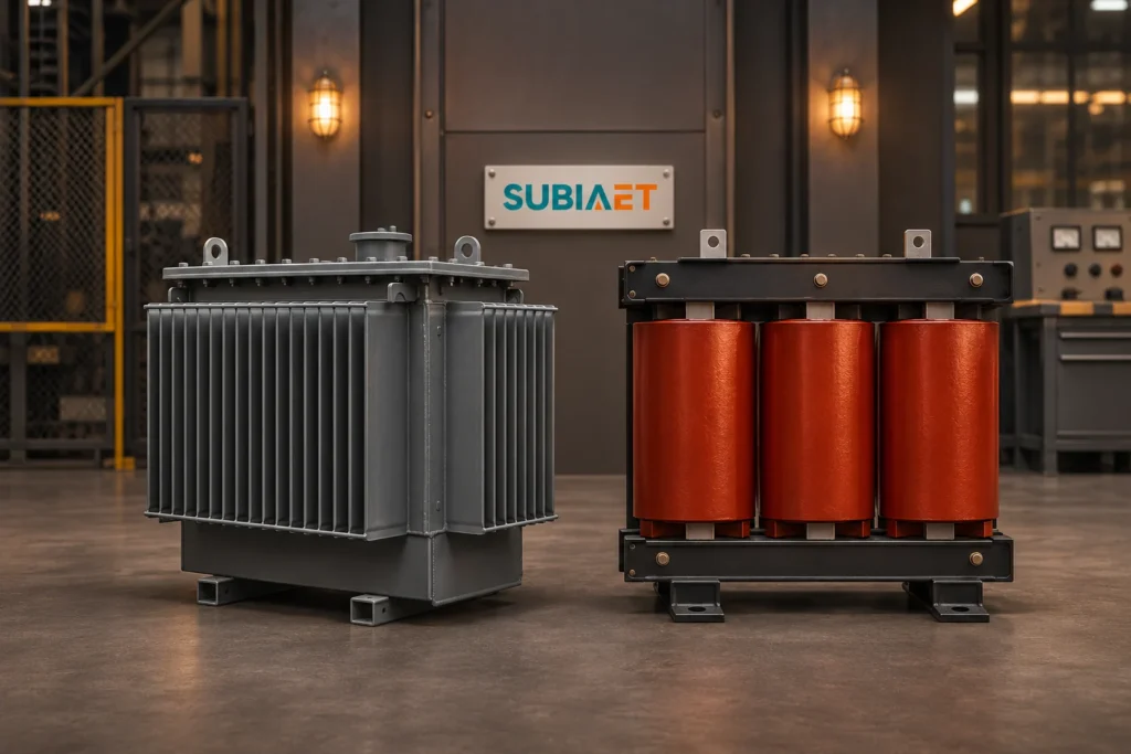
How installation conditions change the choice between oil-immersed and dry-type transformers.

A four-axis guide to transformer types, with a worked classification and the next questions to ask about ratings and installation.
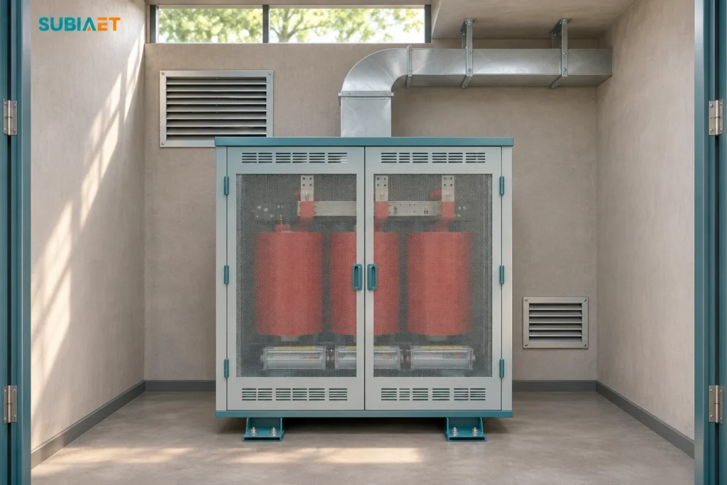
A worked example separates airflow shortfall from a standby condensation risk and sets out what to verify before handover.