Request a Quote
Share the equipment and project requirements. If you need help selecting a model, describe the application.
Have drawings or specifications? Email [email protected] with your project reference.

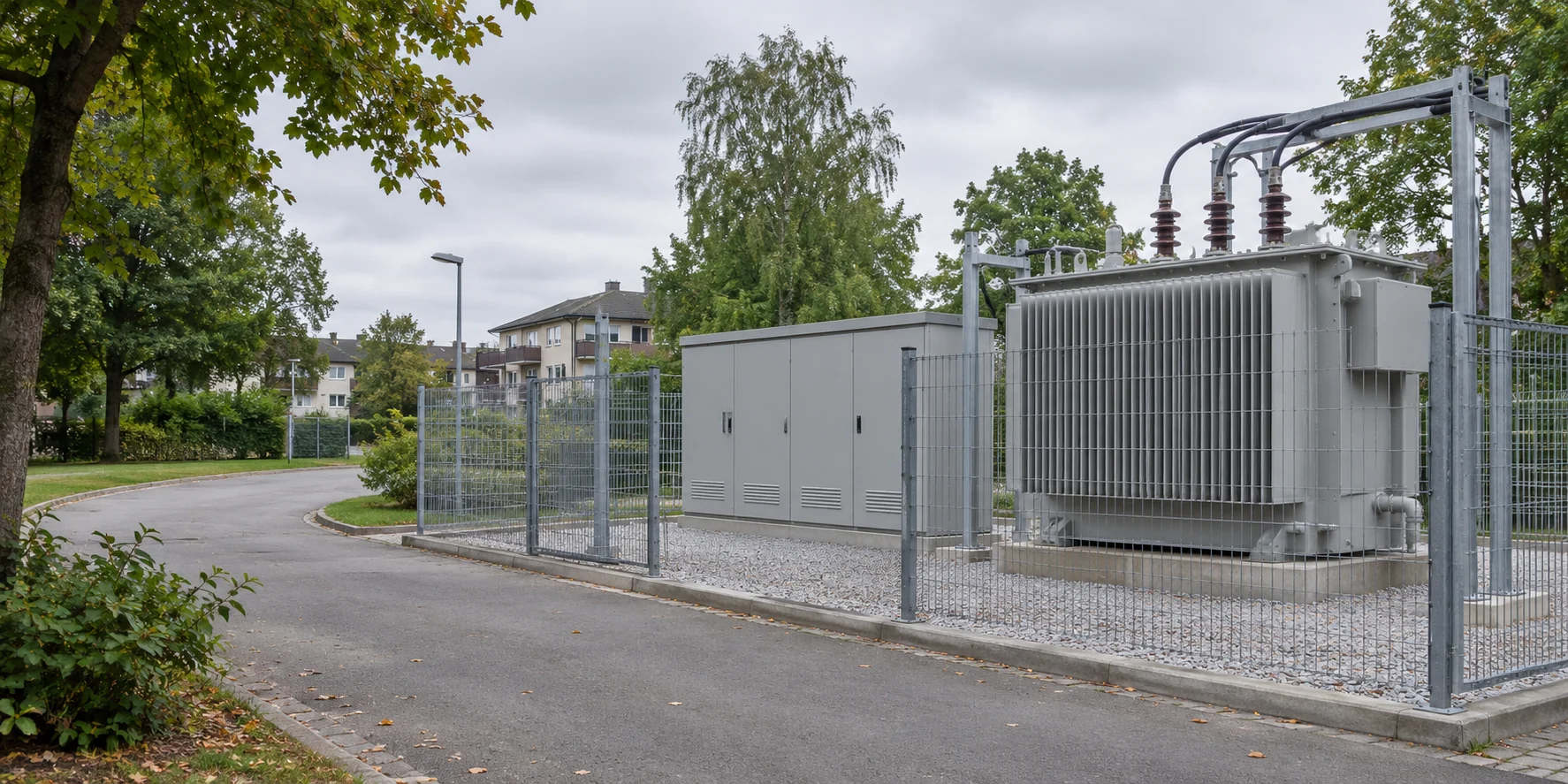
Plan a feeder extension, transformer change or substation upgrade around the circuits that must stay in service. Mark retained equipment, temporary supplies and permitted outage windows on the single-line diagram.
A utility adding a transformer bay or splitting a loaded feeder needs an operating plan for both construction and the final arrangement. Mark the cables, busbars and protection that will remain.
A replacement unit can fit the foundation and still fall outside the planned outage if its cable terminals move or the existing protection panel needs modification. Give bidders the existing and proposed single-lines, the limiting outage window and a dimensioned sketch of the connections that will stay in place.
| Operating condition | Question to settle | What to request |
|---|---|---|
| Before transfer | Which existing feeder or tie can carry the transferred load? | Mark the temporary source, tie and cables carrying the transferred load. Request the permissible loading, protection settings and any customer interruptions from the utility. |
| During the outage | Where do the retained cables, panels and civil works meet the new supply? | Show the isolation boundary and equipment that remains energised. Compare terminal positions, retained cable lengths, shipping dimensions and site connections before fixing the outage date. |
| After energisation | How will the new transformer bay and future feeders connect to the existing bus? | Show the final tie position, feeder names and spare positions. Assign responsibility for protection tests, cable checks, commissioning and handover to the network operator. |
Start with the change shown on the network drawing. Use the same terminal and circuit labels in the equipment schedule and in each supplier’s quotation.
In this example the feeder and LV board stay in place. Compare the proposed unit with the existing installation before agreeing the replacement scope.
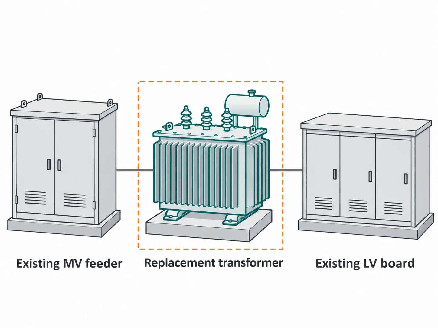
Send the old nameplate and the latest load record. Compare the proposed voltage ratio, tap range, impedance and winding connection with the project requirements.
Photograph both cable approaches and mark terminal heights, orientation and phase identification. Compare them with the supplier’s outline drawing to see whether the retained cables can reach the proposed terminals.
Mark the existing base, fixing points, access opening and route for removing the old unit. Ask for the proposed footprint, handling mass and lifting arrangement.
State the available outage window and which adjacent circuits must remain available. Ask who will disconnect and reconnect the cables, complete site tests and return the circuit to service.
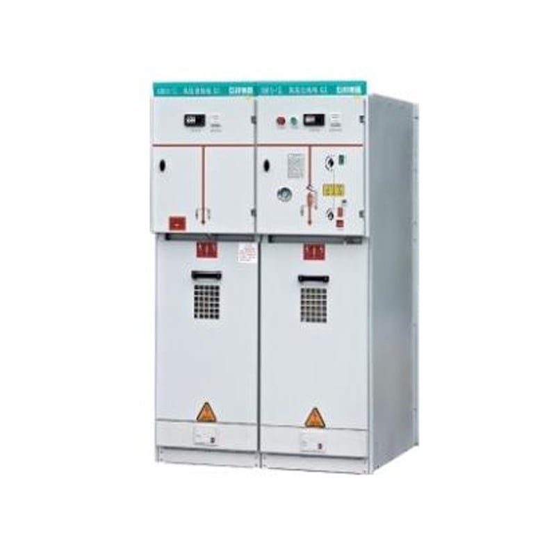
For an extension, match each new panel to its feeder function and identify the connection to retained equipment.
View MV switchgear
For a replacement unit, compare the required electrical duty and terminal positions with the proposed transformer outline.
View oil-immersed transformers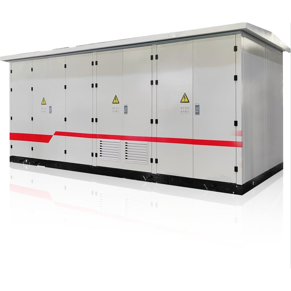
For a new supply point, review the transformer, switching equipment and enclosure as one package, with the external terminals identified.
View prefabricated substations
For a single-phase overhead replacement, check the support arrangement and line connections as well as the nameplate.
View single-phase transformersGive each bidder the same marked-up single-line diagram so the equipment and site work can be compared on the same basis.
Single-line diagram with circuit names, connection point and retained equipment.
Rated voltages, frequency, load or required capacity, and available fault-level data.
Nameplates, site photographs, cable entries, footprint and outage restrictions.
Check each bid against the same drawing. Identify the equipment included, the existing connections and any work priced separately.
| Project | What to mark on the drawing | What to ask the bidder to price |
|---|---|---|
| Extend a feeder | Mark the connection to the existing feeder, incoming and outgoing circuits, and the normally open point if the network is a ring. | List the new panels by circuit. State the switching, protection and metering functions, and identify work at the connection to the existing equipment. |
| Replace a transformer | Identify the MV feeder, LV board, cable ends and foundation you intend to retain. Record the old unit’s nameplate and terminal positions. | Request the proposed transformer data sheet and dimensioned outline. List any cable, termination or foundation changes separately. |
| Add a supply point | Show the incoming feeder, transformer and outgoing circuits. Mark the external terminals and the proposed enclosure footprint. | Request either separate equipment prices or a complete prefabricated station. Ask the bidder to list internal connections, external cable work and site work separately. |