Request a Quote
Share the equipment and project requirements. If you need help selecting a model, describe the application.
Have drawings or specifications? Email [email protected] with your project reference.

In one common PV export arrangement, inverter AC arrives at low voltage, a transformer raises it, and MV switchgear connects the package to a collector feeder. The grid connection may be farther along that collector system. The ordered package can include an enclosure, internal equipment and connections, while separate contracts cover external cables, civil work or controls integration. Before requesting a quote, define that electrical and contractual boundary so each bidder prices the same task.
A sketch without a revision status, mismatched terminal names or an interface left “to be agreed later” makes quotations difficult to compare. One supplier may include termination kits while another leaves them to the installer; both may omit the final SCADA test because neither has been assigned it. The problem is visible before award if the RFQ identifies the equipment, each connection and the party responsible for completing it. A price difference alone cannot show which of those scopes has been included.
Organize the RFQ around four items with a declared status: one controlled drawing, one interface list with named owners, one site data set the supplier can actually design against, and one required shape for the return package. Each of the sections below covers one of them.
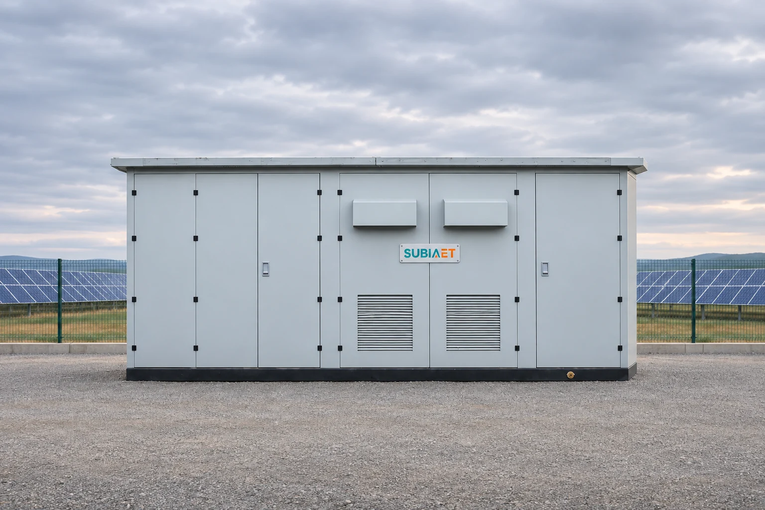
Start with a single-line drawing that carries a title block, a drawing number, a revision letter, an issue date and a status — “issued for quotation” is a different document from “issued for manufacture,” and the RFQ should say which one it is. A family-page photograph can provide visual context, but the actual electrical and supply scope comes from the project drawing and confirmed quotation. Use the same terminal identifiers in the drawing, cable schedule and supplier response.
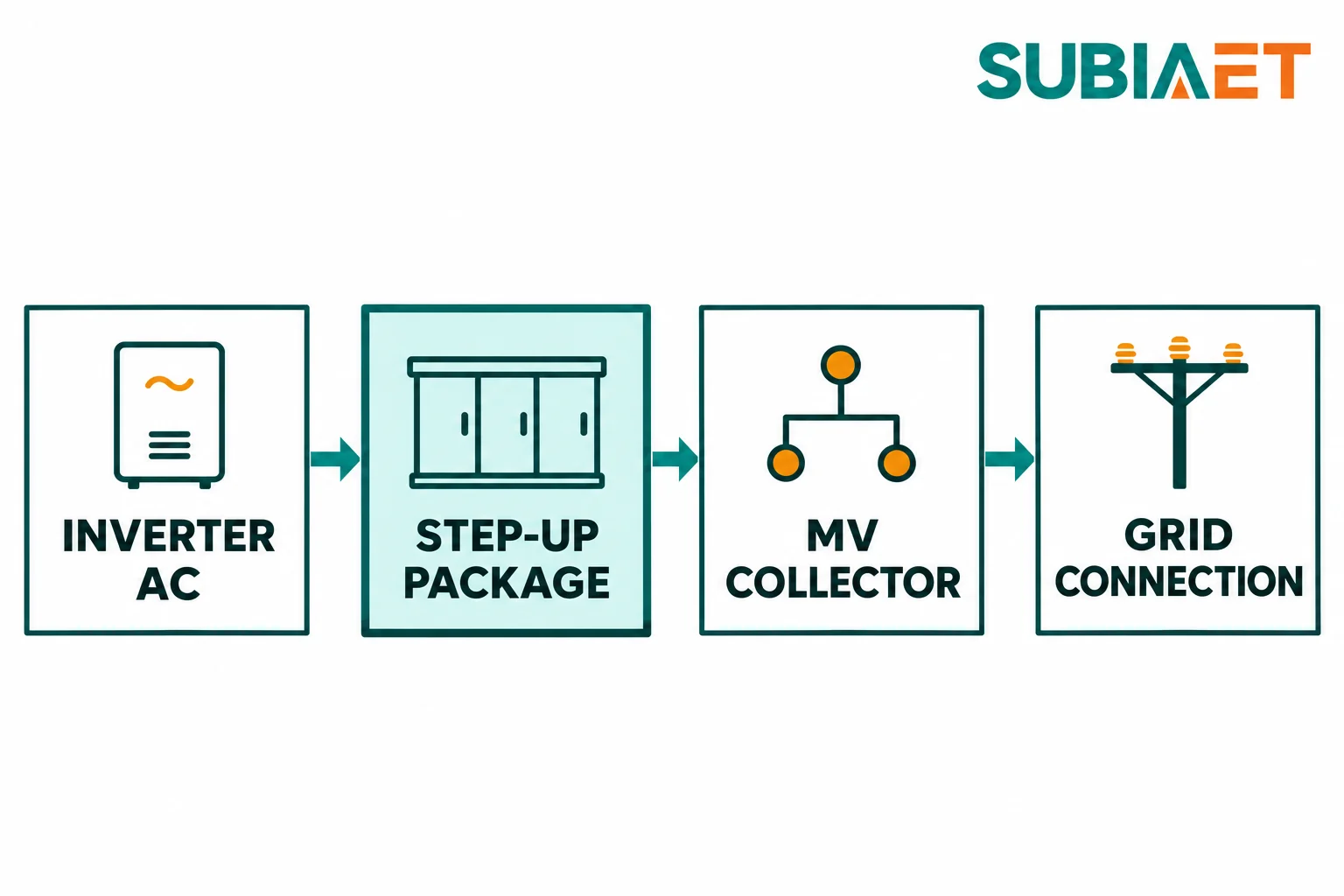
The drawing needs to carry four things that are often collapsed into one arrow and should not be.
Named terminals. Give every connection point an identifier that appears identically in the cable schedule, the protection study and the quotation. The inverter AC terminals, the transformer LV terminals, the transformer MV terminals, the package MV outgoing terminals and the collector feeder terminal should each be a distinct label. When a supplier writes “MV terminals included” against an ambiguous arrow, you have no way to check whether the cable gland plate, the stress cones and the surge arresters are inside the number.
Operating mode and feeder identity. State whether the station runs as a grid-following exporter only, whether reverse power flow into the site is possible, whether the auxiliary supply is drawn from the MV side or a separate LV source, and which collector feeder the station lands on. Review the applicable import and export duties with the protection and metering requirements. Reverse power flow does not by itself prove that a different switchgear configuration is required; the project design determines the equipment and settings.
The point of interconnection, the compliance point, the measurement point and the custody point — named separately. Identify these functions separately even when some share a physical location. Their locations and responsibilities come from the project agreements, rather than an assumed universal arrangement. The interconnection agreement may define compliance at a point on the utility side of the collector, metering may sit at a revenue meter cubicle somewhere else, and the supplier’s delivery obligation may end at the package terminals. The NLR summary of IEEE 1547-2018 is a useful reminder that distribution DER interconnection practice uses a specific vocabulary that separates these points and the stakeholder roles attached to them, and that voltage and reactive power control modes are configurable rather than fixed. That summary is written for U.S. distribution DER and is not a universal rule; use it as a prompt to record what your own agreement actually says, and record which party controls dispatch and protection requirements.
Duty at each named point, with the conditions stated. The RFQ should specify the buyer-confirmed AC voltage and its permitted range, the nominal frequency and range, and the coincident active and reactive power at each point — not the arithmetic sum of inverter nameplates. Coincidence matters: connected inverter MW alone does not establish the simultaneous MW and MVAr through the station. Use the operating cases and controls assumptions in the project study, including reactive support and any relevant import duty. Neither clipping nor a nameplate sum alone establishes whether a proposed station rating is sufficient. Add the worst thermal condition the station must meet — design ambient, solar exposure of the enclosure face, altitude and any derating the project has already accepted — and the earthing arrangement and fault data supplied by the project studies: maximum and minimum short-circuit levels, the applicable X/R ratio and earth-fault duty, each tied to a named location and study revision. A grid-connection fault level is not automatically the duty at the station switchgear.
Finally, mark every value that is not yet confirmed. A simple convention works: each provisional entry gets a flag, an owner and the milestone by which it closes. For example, a provisional collector voltage can be marked with the responsible grid consultant and a project-defined confirmation milestone. Ask bidders to identify where a changed input would affect equipment ratings, price, lead time or layout. A value presented without its provisional status hides that dependency.
Transformer selection — voltage ratio, vector group, impedance, tap range, losses and the inverter interaction behind them — deserves its own treatment and is not something to settle inside the RFQ text. The separate SUBIA guide to inverter-to-transformer selection, vector group and impedance covers that design step; the RFQ should state the agreed results and clearly label any outstanding study inputs.
A compact secondary substation can contain MV switchgear, a transformer, an LV switchboard, the interconnections between them and auxiliaries. The ABB UniPack-G product overview shows one configuration with an LV switchboard. A renewable step-up package may instead provide an LV connection compartment, or include different LV switching and distribution equipment. The single-line and agreed supply schedule determine that scope. State what is included rather than copying a distribution-station package into an inverter connection without checking its role.
Build one scope schedule and give each line one of four pricing statuses: include (in the base price), option (priced separately, not in the total), by others (someone else supplies or performs it), and to confirm (unresolved, with an owner). Then assign design, supply, installation and verification separately where they belong to different parties. The following is an illustrative allocation for discussion, not a default equipment package or a statement of SUBIA supply scope:
Two of those lines deserve their own treatment because material supply and completion of an interface are separate obligations.
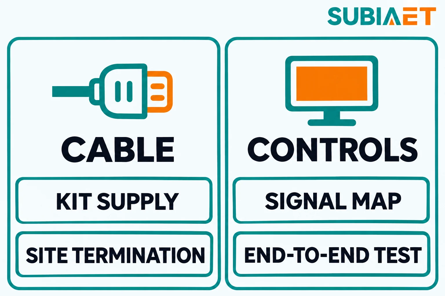
The first is cable kits versus cable work. Including a termination kit prices the material; it does not by itself assign the fitting or testing work. Excluding it leaves the project to assign procurement to a named party and confirm compatibility with the specified cable and equipment. Neither is wrong, but the RFQ must say which, and the quotation must say it back. As a documented comparison point, SMA’s MVPS21MOW-TA-en-25 manual, section 6 places the foundation, the cable entry conduits and the external earthing outside the standard product delivery for the station it describes in Section 6, and notes that site transport and the unloading crane can be requested separately; Section 4.3.7 covers foundation and interface inputs and Section 5.3 covers communication interfaces. That is one vendor, one document revision and a station family that includes inverter configurations — it shows a documented allocation of those lines, not the supply boundary of another manufacturer or station.
The second is the data interface. “SCADA included” is not an interface. The RFQ should require a signal list — every point, its data type, its scale factor and its alarm state — plus the protocol, the physical port and the mapping to the utility or plant master. Then it must name who performs the end-to-end test from the package RTU through the communications path to the receiving system, and who is present when it is done. A factory point-to-point check of the RTU’s own I/O covers a different boundary from proving that the signal reaches the receiving system. Record both boundaries, together with who performs, witnesses and accepts the applicable checks.
Name the authority responsible for the protection philosophy, relay roles and setting approval, such as the utility or responsible project engineer under the project agreement. The RFQ can and should ask the supplier to state what it needs in order to set relays — fault levels, CT ratios, coordination study results, the settings authority — and to identify which of those it expects to receive.
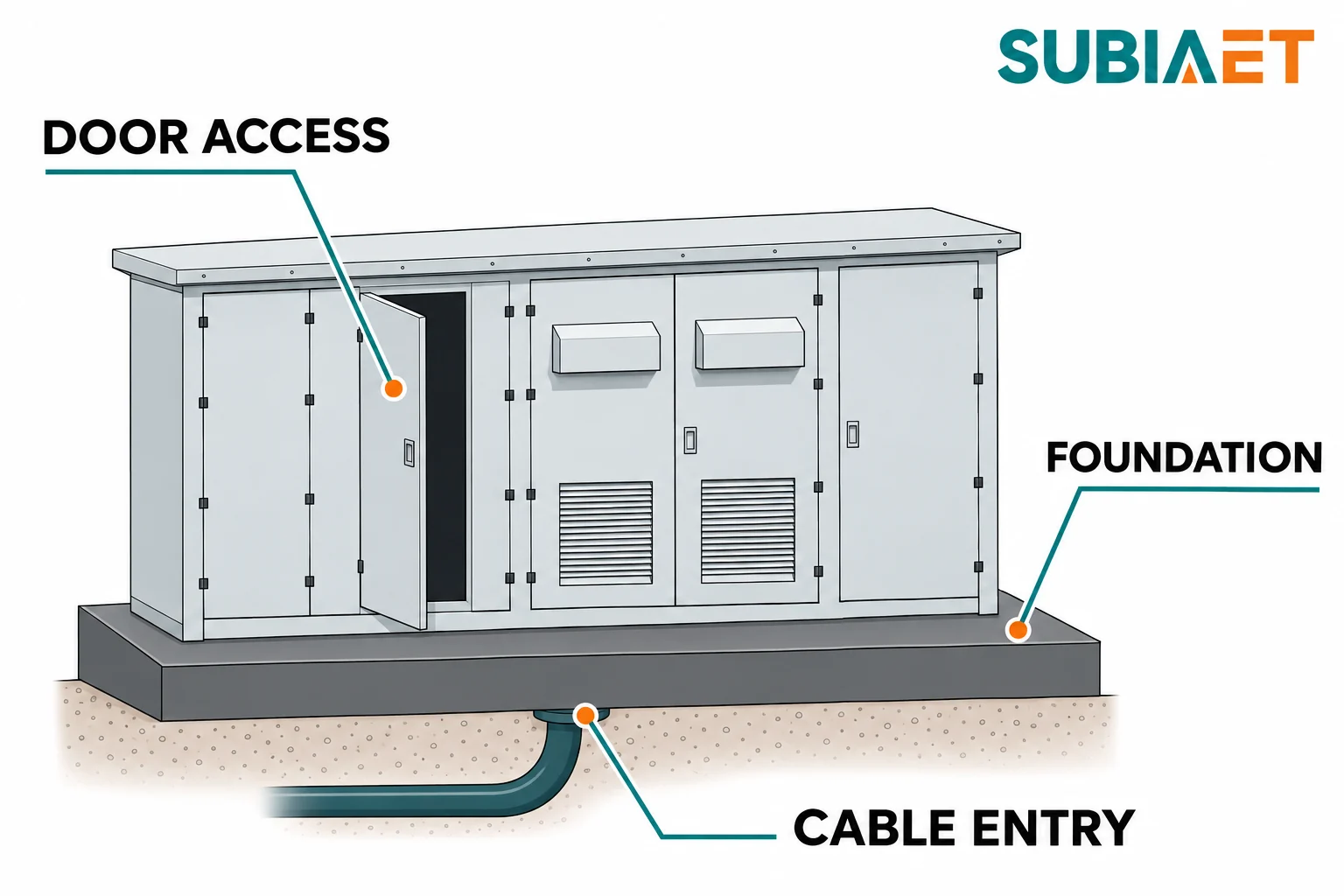
An enclosure general arrangement is a derived document: it falls out of what goes inside, how it is cooled, how it is accessed and how cables reach it. An unresolved input can affect the layout and the civil interfaces. Identify the assumptions that may change the drawing and the milestone at which the civil team needs them confirmed.
Record the environmental inputs explicitly. Design ambient temperature and its duration, solar exposure of each face and whether the station sits in open sun or shade, altitude, corrosivity category for the site atmosphere, dust or sand load, humidity, seismic and snow/wind criteria where the enclosure structure depends on them, and the groundwater or flood level with the drainage arrangement. Water conditions inform the base, cable-entry and drainage design. State the relevant levels and exposure so the supplier and civil team can agree the required interfaces and protection, rather than inferring them from a generic enclosure outline.
Record the physical inputs. Installation footprint and the access envelope around it, including door swing, the route a replacement transformer would take and the space a crane or lorry needs. Cable approach from each side — number of cables, outside diameter, minimum bend radius, entry direction and whether entry is from below. Earth termination points and where the site earth grid will arrive. Any constraint from the civil design already fixed, such as a plinth that cannot move.
Then require the outputs that civil needs before it can be released: a general arrangement drawing, shipping masses and the split points if the enclosure ships in sections, door and entry clearances, base loads at each support position, and the approved lifting and support points with the supplier’s own handling requirements. Assign responsibility for transport, unloading and lifting, and any assembly at the site. These project outputs should not be inferred from a catalogue outline. ABB’s UniPack-G catalog illustrates how doors, base construction and oil collection arrangements can differ across one product family.
Thermal performance deserves a specific request rather than a general assurance. The public IEC 62271-202:2022 synopsis describes stated service conditions, rating characteristics, structural requirements and test methods for enclosed, cable-connected AC prefabricated substations within its scope, and highlights assembly ratings, temperature-rise methods and an informative annex on solar radiation. The useful implication for an RFQ is that the rating of the assembly in its enclosure under stated conditions needs evidence applicable to that arrangement, alongside the ratings of its individual components. So ask for the thermal basis of the proposed configuration: what ambient and solar assumption was used, what internal temperature the equipment is rated to see, and what evidence supports that for this assembly. Whether that edition and scope apply to your project is a decision for the project, and a standard’s synopsis is not a certificate for any particular configuration.
If the transformer is oil-filled and the site requires oil containment, say so and specify it — retention capacity, whether the base is a collection pan or a full bund, drainage or detection. Base and oil collection arrangements differ between configurations and between suppliers, so this is a line item to state, not to assume.

The return package determines whether you are comparing offers or comparing cover pages. Require the same six deliverables from every bidder, in the same order:
Now compare two illustrative offers for the same station. Offer A excludes the MV cable termination kits. Offer B includes them. Both leave the end-to-end test from the package RTU to the grid SCADA master open, with no named party. The totals do not yet describe a common completed scope. Obtain the exact kit specification, supply and delivery terms for each offer, then confirm who fits and tests the connections. Separately assign the controls test to the appropriate contractor; a line marked “SCADA included” does not close that obligation.
Normalising means obtaining equivalent kit scope and pricing for Offer A and checking whether any associated accessories, delivery or fitting work differ. Have the appropriate party price and accept responsibility for the end-to-end controls test. If a comparison must proceed with an allowance, keep it visibly provisional until its scope and owner are agreed. Then compare the bids against that common boundary, with deviations and remaining open items recorded. This does not establish that the higher or lower initial price is better; it establishes what each price actually buys.
Before issue, check the four parts of the RFQ together. Is the single-line at a named revision, with a status that says it is for quotation? Does every terminal on it appear identically in the cable schedule and the protection study? Are the point of interconnection, applicable performance point, package terminals, metering point and contractual handoff identified, including any that share a location? Does every provisional input have an owner and a close-by milestone? Is there one scope list marking include, option, by others and to confirm, with the LV interface and cable termination kits either decided or clearly assigned as provisional? Has the site data set been issued with ambient, solar, altitude, corrosivity, water level, footprint, cable entry and earth termination? And does the RFQ require a marked-up single-line, a scope matrix, a GA, an interface schedule, service-condition assumptions and an evidence matrix in return?
The SUBIA PV step-up substation family shows an enclosed package form. For more on the equipment roles, see prefabricated substation components and power flow. A marked-up single-line and interface list give the supplier a concrete starting point for a project quotation.
Yes, for a budget quote based on explicit assumptions. Label provisional values, assign each to a party and state when it will be confirmed. Ask bidders to show which equipment ratings, commercial terms or drawings depend on those assumptions.
The LV equipment depends on how the inverters, auxiliary loads and protection connect. The single-line and scope list should show whether the supplier is pricing terminals, an LV switching compartment or a separate switchboard.
The project drawing and agreement determine those locations. Identify the station terminals, grid connection, applicable measurement point and contractual handoff explicitly. Each can have a different owner or acceptance requirement.
A coordinated general arrangement, support loads and positions, cable entry details, door and replacement clearances, and the applicable drainage and containment interfaces. Confirm the delivery and unloading arrangement against the site access plan.
Component reports cover the equipment and conditions named in each report. Ask for separate evidence that addresses the proposed assembly and its service conditions, along with a list of gaps and the factory or site checks needed to resolve them.
