Request a Quote
Share the equipment and project requirements. If you need help selecting a model, describe the application.
Have drawings or specifications? Email [email protected] with your project reference.

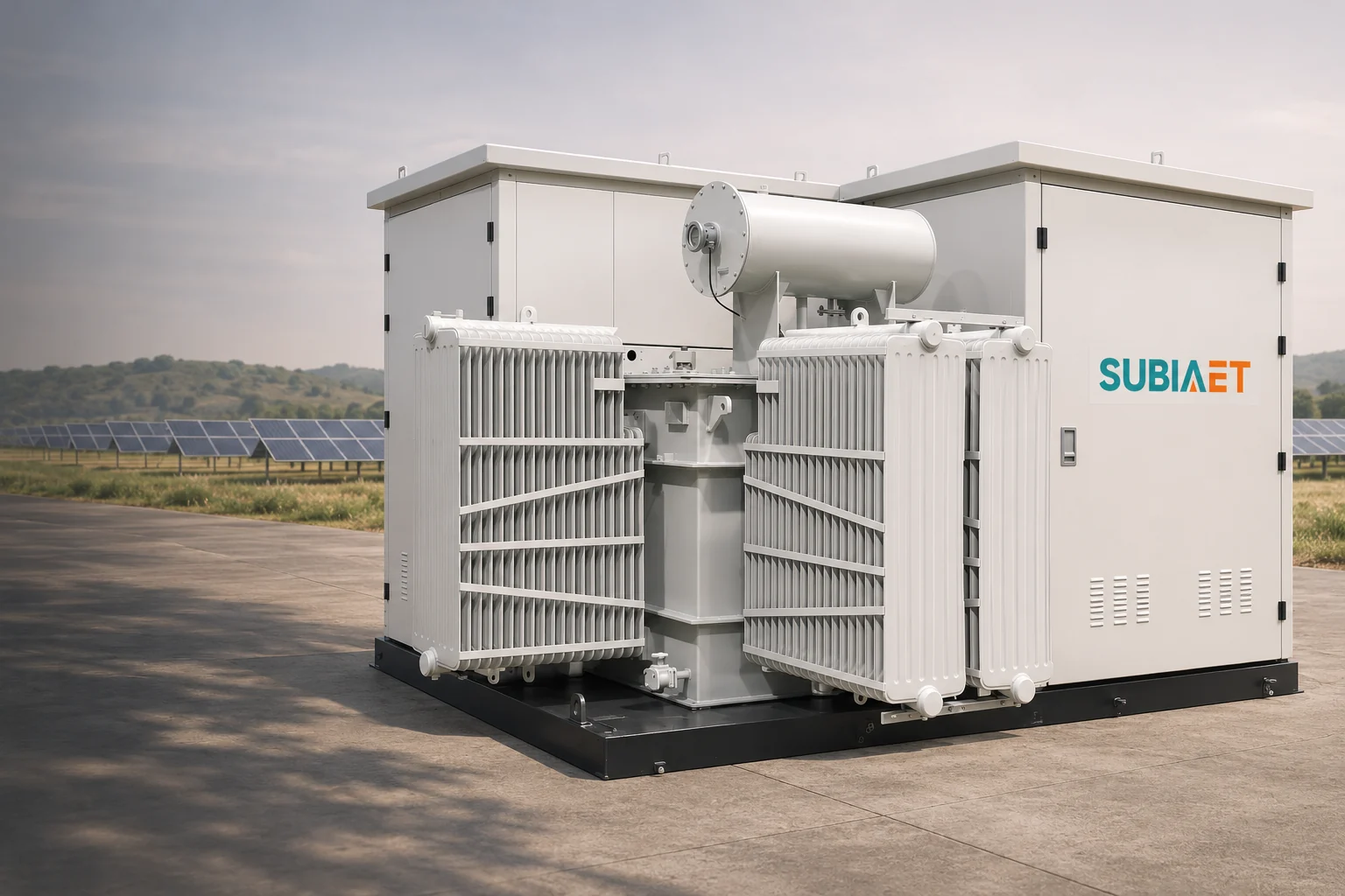
A solar inverter does not connect to a generic transformer. It connects to a specific low-voltage winding whose voltage, insulation level, earthing and impedance were each chosen against one inverter manual, one collector design and one interconnection study. Reading those documents in isolation can leave mismatches unresolved: a voltage window copied off a datasheet straight onto a nameplate, a vector group inherited from a previous project, an impedance percentage compared against a different MVA base, or a megawatt figure from an interconnection agreement treated as the transformer’s rating.
This article works through the four checks in the order the physical circuit imposes them — AC voltage at the terminals, winding connection and earthing, impedance on a common base, and finally the P/Q duty those windings actually carry.
Start at the inverter’s AC terminals and follow the circuit outward. The array’s DC voltage belongs to the inverter input. Match the transformer’s low-voltage winding to the inverter AC output and the project’s AC study, rather than copying the PV string or DC-bus voltage into the transformer specification.
From the LV winding the circuit continues through the MV winding to the collector bus, along the feeder to the substation, and out to the interconnection point. That interconnection point is a separate location with its own voltage and its own contractual meaning. It is not the inverter terminals and it is not the DC array, and a voltage requirement written at one of those three places does not automatically transfer to the others.
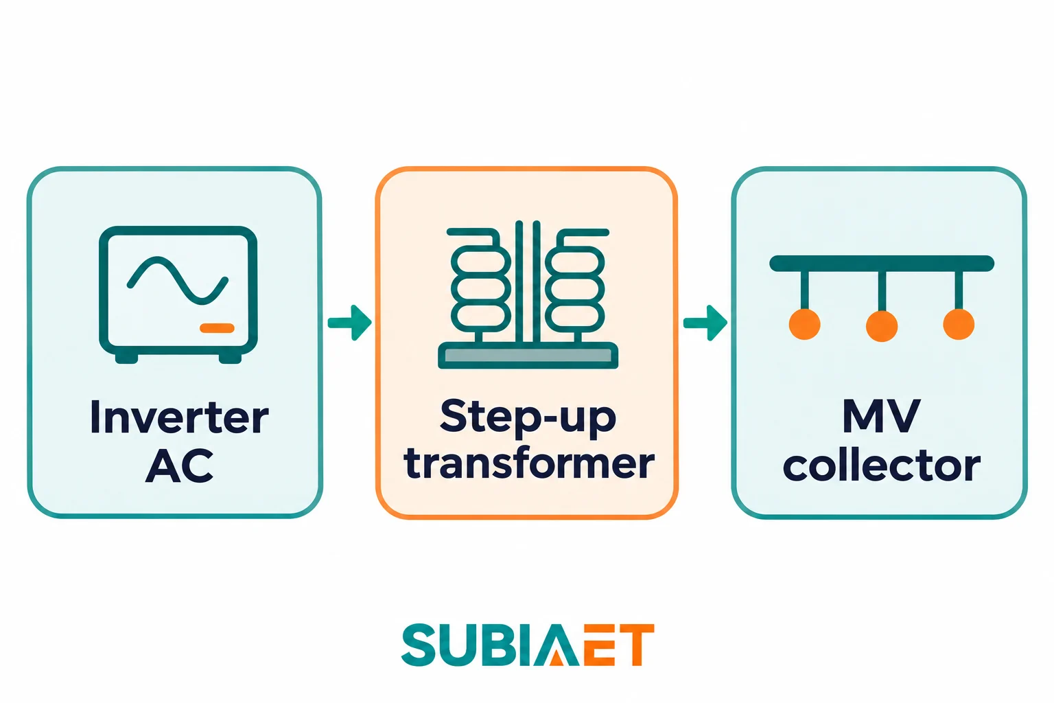
Four numbers from the inverter manual decide the LV winding: nominal AC voltage, permissible AC operating window, nominal frequency, and maximum AC current at the relevant conditions.
The Sungrow SG350HX-US manual, Ver14, §§5 and 10.1 gives 800 V AC nominal, a 704–880 V AC operating range and 60 Hz nominal. Read those as two different kinds of information. The 800 V nominal is an input to the winding specification. The 704–880 V band describes an inverter operating limit; it is not a transformer rating and it is not a guarantee of full power across the whole band. A nameplate that quotes the top of the window as the winding voltage has quietly changed the design point.
The band requires checks at both ends. At 880 V on a fixed 60 Hz, the applied volts per hertz are ten percent higher than at 800 V. Check the transformer’s permitted excitation conditions at the actual tap; that arithmetic alone does not predict its loss or sound level. At a lower AC voltage, carrying the same apparent power requires more current. Use the inverter’s current limit and capability data to determine how much power is actually available at 704 V and the relevant temperature. Check the LV winding, cables and switchgear against credible current conditions instead of assuming full power across the complete voltage window.
On the network side the inputs are the collector nominal voltage, the network’s own minimum and maximum operating voltages, the tap range needed to cover that range, and the insulation level of the collector system. Tap selection is a ratio decision: an off-circuit tap on the MV winding shifts the LV voltage the inverter sees for a given bus voltage. Evaluate the proposed taps so the inverter terminal voltage stays within the applicable limits at the highest and lowest credible bus voltages and load conditions. Record the tap at which impedance is specified and ask for the values needed at other operating taps; do not assume that one quoted percentage describes every condition.
Insulation to ground needs its own decision. The LV winding’s insulation requirements are not set by 800 V line-to-line alone. Check the inverter manufacturer’s conductor-to-ground requirements, the approved earthing arrangement and relevant inverter operating modes. The SG350HX-US transformer section calls for thermal, ambient and insulation review. Distinguish line-to-line voltage from conductor-to-ground stress, and distinguish power-frequency withstand from impulse insulation ratings. These are separate inputs to the equipment specification; neither the nominal AC voltage nor a generic account of an MV earth fault settles all of them.
Keep inverter derating and transformer derating apart. They are different curves with different causes, and both may constrain the same hot-afternoon operating case. Compare the inverter’s available P/Q and current at the site voltage and temperature with the transformer’s permitted loading under its own ambient, altitude and cooling conditions. An inverter power reduction does not by itself establish the transformer thermal rating, or vice versa.
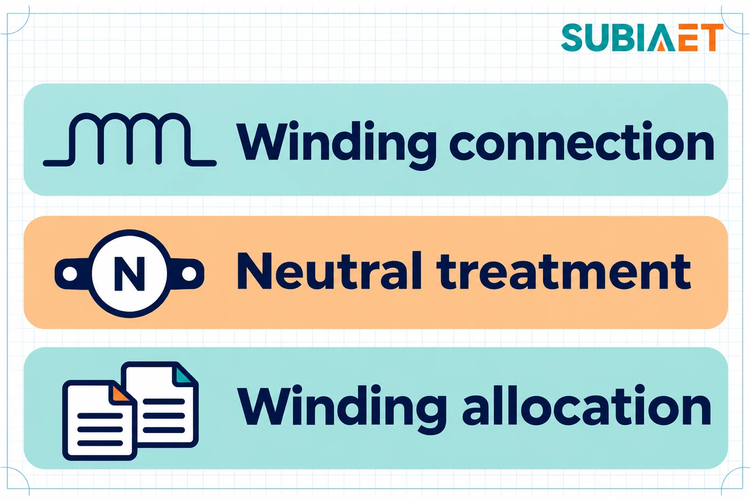
A vector group is a compact description of three separate decisions: how each winding is connected (star, delta, zigzag), what phase displacement exists between the windings (the clock number), and which neutral points are brought out. Specify all three explicitly; a winding-connection label without the clock number or neutral treatment leaves the complete arrangement undefined.
Winding connection and clock. The exact inverter manual determines the permitted configurations. For the SMA STP 125-70, the inverter-side winding is grounded wye and a neutral conductor connection from the inverter to the transformer neutral is not required. The SMA commercial planning guide lists YNyn and Dyn as compatible configurations for that model and YNd as incompatible. These are winding-connection configurations, not clock numbers. Confirm the actual phase displacement and network coordination separately; do not invent a reason for an excluded configuration or transfer this table to another inverter model.
Neutral and earthing. Three things get conflated here and should not be. The neutral conductor is a current-carrying conductor in a four-wire system. The earth connection is a bond from a winding neutral point to the earthing system, and it may be direct, through a resistor or through a reactor. Protective earthing is a separate obligation; it must not be inferred from the presence or absence of a neutral conductor. A winding can be earthed at its neutral without any neutral conductor being run to the inverter — that is exactly the STP 125-70 situation, where the inverter-side winding is grounded Wye but no neutral conductor connection is required. For the covered single-inverter, two-winding arrangement, §2.2 of SMA’s Sunny Central document SC_Trafo-TI-en-71 goes a step further: an LV neutral terminal, if present, must remain unconnected and ungrounded. A terminal that exists on the transformer is not an instruction to use it.
Winding allocation. How many LV windings the transformer has, and whether two inverters may share one, is an OEM question rather than a layout preference. For covered Sunny Central systems each inverter has its own galvanically isolated LV winding, the LV winding matches the inverter AC output and the collector side matches the network. The same SMA document also covers four-winding cases, and those use different impedance bases and require different winding-pair checks. Ask the actual inverter supplier which units may share a winding and which require separate windings. A similar project is not approval for a different allocation. Check the proposed winding connections, clock number, earthing and required pair impedances on the same drawing; sharing a winding does not by itself redefine a chosen impedance base.
Shield. An interwinding shield and its grounding are separate specification items. For covered Sunny Central systems a grounded interwinding shield is recommended. The SG350HX-US transformer section does not require a shield winding for that model and instead calls for thermal, ambient and insulation review. Neither statement is universal, and neither substitutes for the other design work: a shield does not settle harmonic losses, insulation coordination or the earthing scheme. A transformer can have a shield and still have the wrong winding connection. Record the requirement for the exact inverter rather than treating “solar transformer” as a sufficient shield specification.
Percentage impedance expresses the transformer’s series impedance relative to a chosen base. For a balanced three-phase system, using line-to-line base voltage in volts and total three-phase base power in VA:
z% = 100 × Z(Ω) × S_base / V_base²
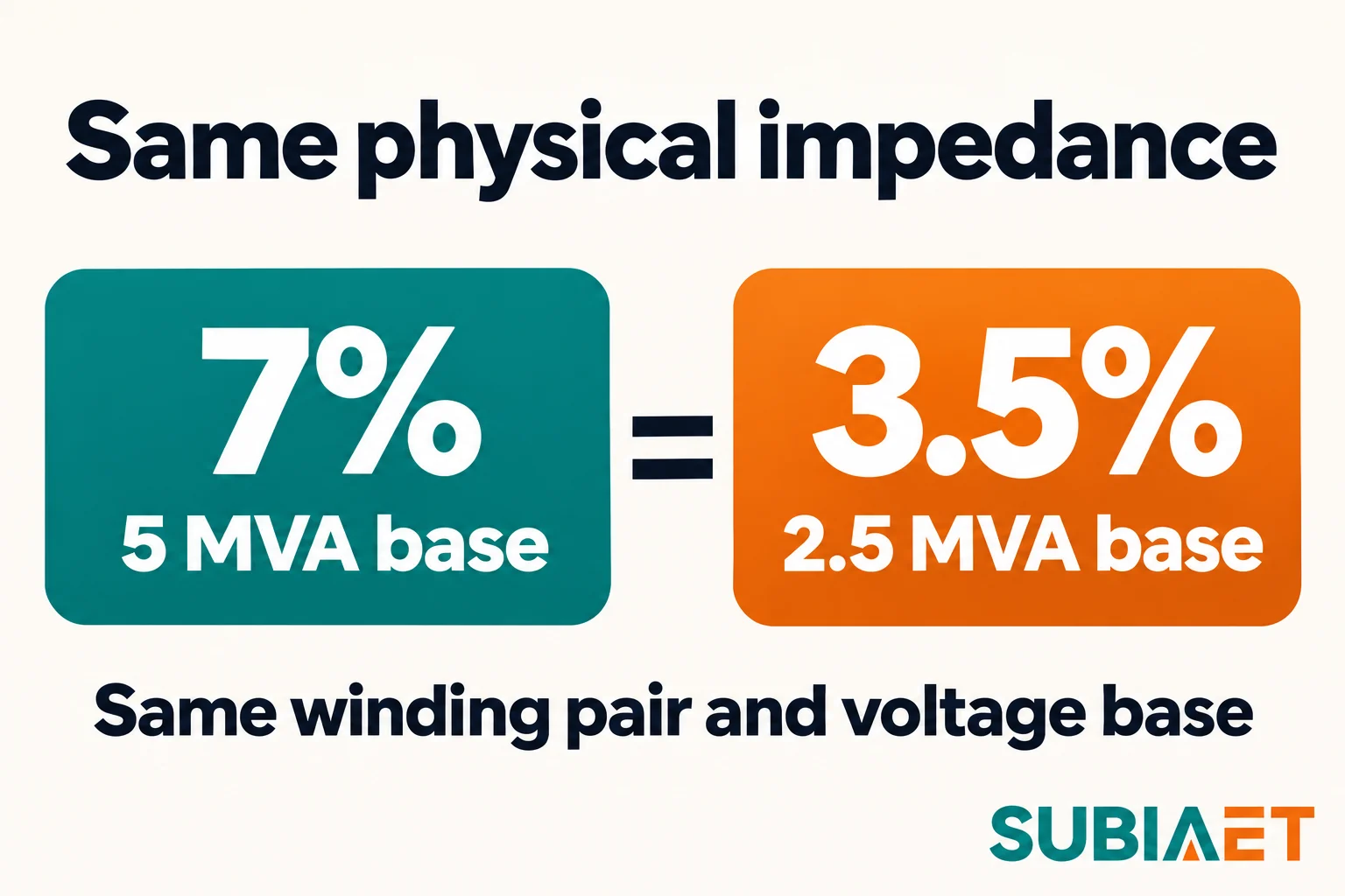
Because the base appears in the expression, the same physical transformer produces different percentages against different bases. Change the MVA base and the percentage changes in proportion; the ohms do not move.
Before comparing any two impedance figures, pin down five things: which winding pair the figure refers to, the tap position, the voltage base, the MVA base, and the tolerance band. Without all five the two numbers are not comparable, however similar they look on a quotation sheet.
For SMA SC 2500-EV, the two-winding example in SC_Trafo-TI-en-71, §§2.2 and 4.2 gives 5.0% minimum, 6.0% nominal and 8.5% maximum. The stated two-winding path between the inverter output and grid connection point uses nominal transformer power as its basis. Confirm the endpoints of that requirement: an acceptance limit along a connection path is not automatically identical to a factory test value for the transformer winding pair. The same document’s four-winding cases use different bases and additional winding-pair checks. Quoting 6% as a general target for a PV step-up transformer would misapply a model-specific document.
The base conversion is easy once seen. Take a hypothetical transformer with 7% impedance on a 5 MVA base at a defined voltage base. Re-express the identical winding pair at 2.5 MVA on that same voltage base:
| Base | Percentage | Impedance in ohms at 0.8 kV |
|---|---|---|
| 5 MVA | 7.0 % | 8.96 mΩ |
| 2.5 MVA | 3.5 % | 8.96 mΩ |
Nothing physical changed. The two labels describe one transformer. In a simplified three-phase bolted-fault calculation at 0.8 kV, ignoring upstream and connecting-circuit impedance and other contributions, 800 / (√3 × 0.00896) is about 51.5 kA for either base expression. This is a transformer-limited illustration, not the project fault level. The actual grid, cables, inverter behavior and fault location belong in the fault study. Comparing 7% with 3.5% without their bases would mistake two expressions of the same impedance for different equipment; different quotations can also represent genuinely different designs.
What the number does in the network depends on the complete circuit. With other conditions fixed, more series impedance limits a grid-fed fault current, but the actual fault duty includes the source and connecting impedances. Voltage rise or drop depends on resistance and reactance, current, power factor and power-flow direction. A percentage magnitude alone cannot predict the result or establish inverter-control compatibility. Check the proposed transformer, cables, grid equivalent and inverter behavior together in the project study rather than ranking a larger or smaller percentage as universally better.
Three checks belong alongside the impedance figure. First, the voltage study: check the relevant export and other operating cases at the inverter terminals and collector bus. Second, protection: establish the fault levels and duties at the named locations, including source, cable and transformer impedance and the applicable inverter contribution. Third, acceptance: inverter manufacturers and network operators may apply limits to different connection paths or measurement points. Identify those endpoints and bases before comparing a factory test result with a system requirement. Keep the transformer test value distinct from the total impedance that the inverter or grid study evaluates.
Keep the network equivalent impedance separate from the transformer’s own specification. The network equivalent behind the interconnection point is a study input; the transformer’s specified and tested winding-pair impedance is an equipment input. They combine when you refer them to a common base, but neither number substitutes for the other in the fault calculation.
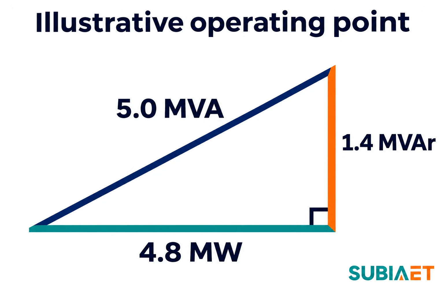
The last check connects the interconnection documents to the equipment. An agreement states a P/Q requirement at a named point. FERC Order No. 827 illustrates why that name matters: for the cases it covers, the reactive-capability requirement is stated at the high side of the generator substation. Mark the actual compliance point and all intervening equipment on the project single-line. Do not assume that the generator-substation high side and the point of interconnection occupy opposite sides of one transformer, or that a requirement at one location is the loading at every other location.
In a fictional example, suppose a project agreement places a requirement of 4.8 MW and 1.4 MVAr at the same defined point, simultaneously. The apparent power there is the vector sum:
S = √(4.8² + 1.4²) = √(23.04 + 1.96) = √25.0 = 5.0 MVA
for a fundamental, sinusoidal, balanced condition. That is the number that matters — not 4.8, and not 4.8 + 1.4. Adding MW and MVAr arithmetically overstates the duty badly; ignoring the MVAr entirely understates it.
As a deliberately simplified illustration, assume one transformer carries both components at that point and ignore losses. The transformer then carries 5.0 MVA in that simplified condition. Selection still requires the actual terminal currents and the applicable site and thermal conditions. That simplification is the starting point, not the selection.
Four things separate the illustration from the real loading.
Where the reactive power is produced. If a capacitor bank, STATCOM or other reactive-power equipment is connected on the MV bus, part of the requirement at the compliance point may be supplied without crossing the selected inverter transformer. A plant controller commands equipment; it is not itself the reactive-power source. If instead the inverters supply the reactive power, its current crosses the LV winding. Mark the source location, direction of reactive power and measurement point, then calculate the actual P and Q through the transformer. The compensation location can change that duty; its effect must be calculated rather than ranked against impedance in the abstract.
Losses. For PV export from LV to MV, the real power leaving the MV terminals is lower than the power entering the LV terminals by the transformer’s losses: P_MV = P_LV − P_loss. To deliver a specified MV output, the LV input must cover those losses. Use the actual loss data and terminal P/Q from the load flow rather than adding an assumed universal percentage. Reactive flows also need their own calculation; MW and MVAr at the compliance point are not automatically the simultaneous values at the transformer terminals.
Inverter capability limits. The inverter’s current limit and P/Q capability couple real and reactive output. Depending on voltage, temperature and the actual capability curve, delivering the example 1.4 MVAr may require reducing MW below 4.8. The capability curve, not the nameplate ratio, decides what the plant can actually produce at the moment the network needs it.
Time of day and cooling. At night the array produces no solar power, but the project may specify reactive duty if the chosen inverter and plant arrangement support it. Establish whether and how the transformer remains energized and loaded in that mode. Night-time reactive duty then becomes a separate operating state with its own current, losses and temperature conditions. Compare the daily load curve with the available cooling stages and site ambient; annual average loading cannot establish the rating needed for the highest applicable thermal duty.
Harmonic current is a separate thermal input. Non-sinusoidal current affects RMS current and frequency-dependent winding and stray losses. Ask the transformer supplier to assess the expected harmonic spectrum and operating current with the specified ambient, altitude and cooling conditions. A fundamental-frequency MVA calculation alone does not quantify those additional losses, and an unexplained percentage capacity margin does not replace the thermal review. This does not mean every PV installation requires a special transformer design; the actual inverter and project conditions determine the assessment.
The enquiry is where all four checks become a specification. For a project of this type the useful package is:
The SUBIA PV step-up substation page shows an example of an exposed transformer between equipment cabinets. The electrical match and the equipment included in the package are confirmed in the project documents. For background, see the guides to transformer impedance, vector groups and harmonic duty.
Use the inverter’s AC output data and the project’s AC study for the transformer winding. The array’s DC voltage belongs to the inverter input.
Check the inverter’s connection instructions. The SMA STP 125-70 example requires a grounded wye winding on the inverter side without a neutral conductor to the inverter. Verify protective earthing separately.
They may use different bases, winding pairs or tap positions, or offer different physical designs. Ask for the stated conditions and compare the values on a common base.
Check the duty at the transformer itself, including where reactive power is supplied, losses, operating voltage and the current and cooling conditions over time.
Check the transformer requirements for the exact inverter. The covered Sunny Central document recommends one, while the SG350HX-US document does not require one for that model.
