Request a Quote
Share the equipment and project requirements. If you need help selecting a model, describe the application.
Have drawings or specifications? Email [email protected] with your project reference.

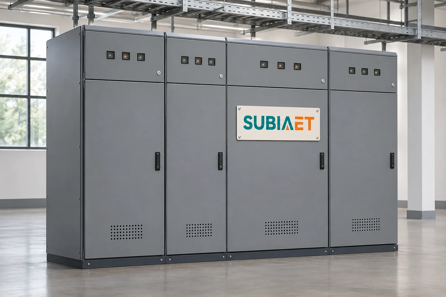
In the distribution example used here, electrical switchgear is an assembly of switching devices, protective equipment and associated apparatus arranged to receive incoming power, distribute it through a shared busbar, and deliver it to outgoing feeder circuits. That is the assembly-level meaning most engineers encounter when reading a distribution specification. The broader term is wider than this: according to the IEC vocabulary definition reproduced by GSO, switchgear covers switching devices individually, combinations with associated equipment, and complete assemblies. A single circuit breaker is therefore switchgear in the broad sense, while a metal-enclosed lineup of panels housing multiple breakers, busbars, instrument transformers and protection relays is switchgear in the assembly sense. Keeping these two meanings separate prevents the common mistake of treating a device specification as equivalent to an assembly specification.
This article traces the physical layout of a bus-fed lineup, distinguishes the three separate circuit duties performed inside it, explains the classification axes used to describe types, and shows where the assembly fits in a facility that also contains a transformer, a main LV board and downstream panelboards.
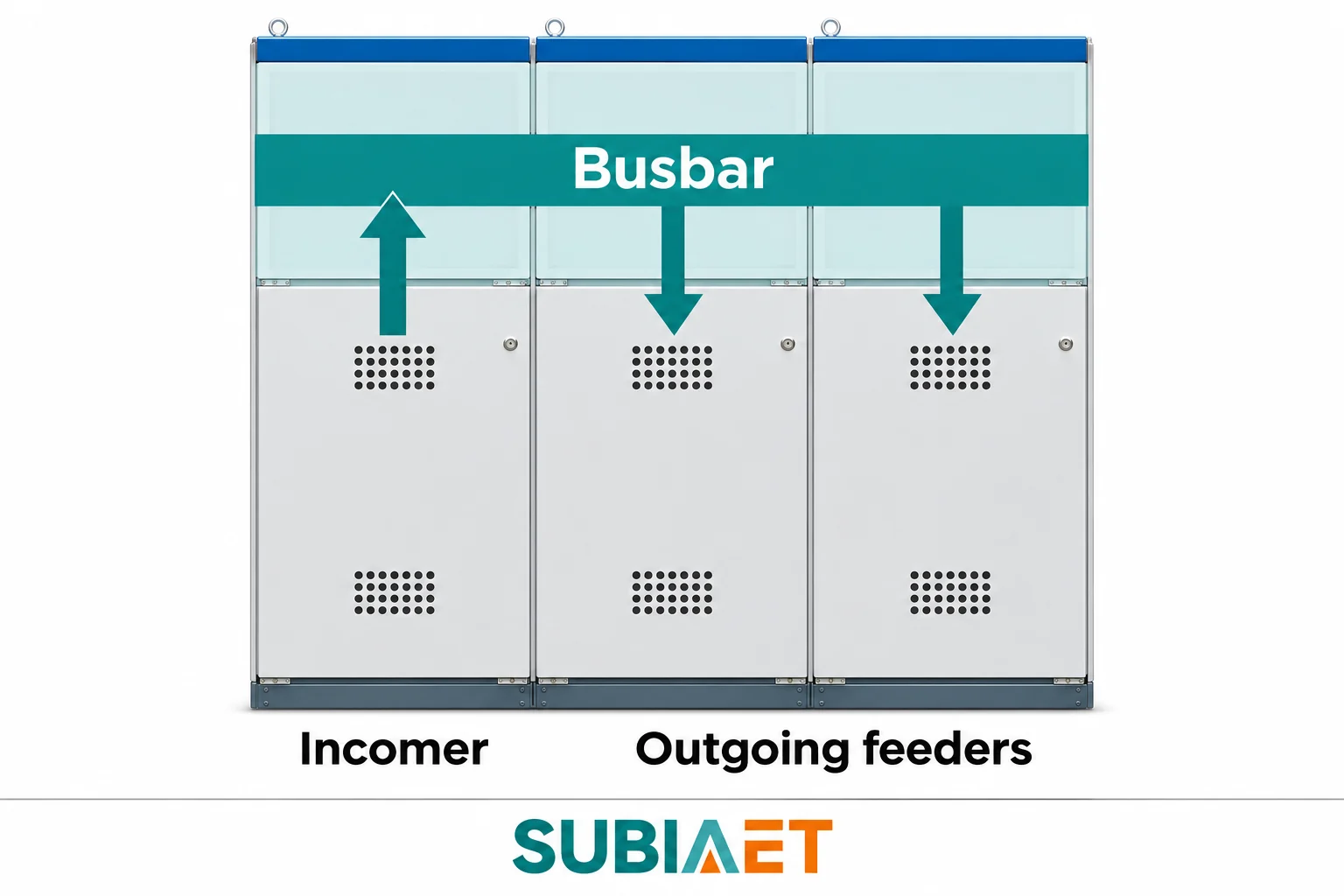
A switchgear lineup in a substation or switchroom typically organises its functions along a physical sequence that is straightforward to read once you know what each section contributes.
The incoming section receives power from the upstream network or transformer. It contains the incoming devices assigned by the protection and switching design. A circuit breaker can combine switching with fault interruption; a switch-disconnector provides its specified switching and isolating functions, while fault protection requires an appropriately rated device. Current and voltage instrument transformers may be placed here, or in feeder sections, to provide scaled measurement signals to metering and protection relays.
The busbar is a set of conductors — usually copper or aluminium bars — running the length of the assembly. Its job is simply to carry power from the incoming section to the outgoing sections connected to that bus. A busbar fault can affect several connected feeders, so its protection and the fault duty of the assembly need consideration separately from a fault on one outgoing circuit.
The outgoing feeder sections tap from the busbar and deliver power to individual loads, sub-distributions or the next transformation stage. Each feeder section typically contains its own switching device and may contain a protective device, measurement instrumentation and control wiring. In a medium-voltage lineup the feeder device is often a withdrawable or fixed circuit breaker; in certain ring-main configurations it may be a load-break switch with a separate fuse.
The key distinction to carry into a specification review is this: a circuit breaker is one device inside the assembly. The assembly coordinates many devices — the breaker, busbars, instrument transformers, relay, cables and enclosure — into a system capable of receiving, measuring, protecting and distributing power. A specification that lists only the breaker rating is incomplete; the assembly ratings for short-time withstand current, insulation level and busbar capacity are separate parameters.
The SUBIA site has both medium-voltage switchgear and low-voltage switchgear categories, and the broader MV and LV distribution equipment category page describes the range.
Schneider Electric’s guide to medium-voltage switchgear provides component and assembly examples.
Inside a switchgear assembly, three distinct circuit duties are assigned to devices that may perform one or more rated functions. Treating them as interchangeable is one of the most consequential errors in reading a one-line diagram.
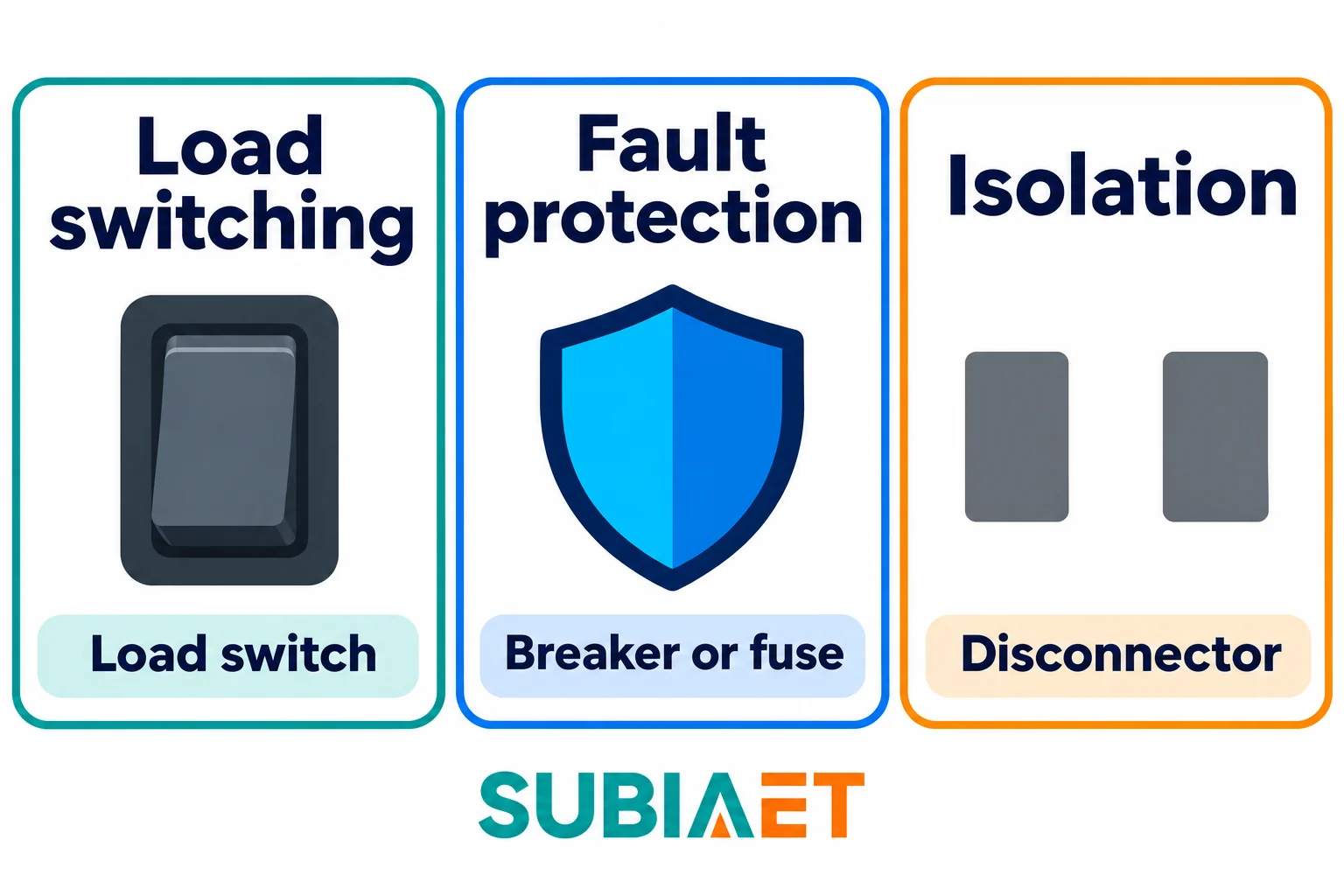
Ordinary switching connects or disconnects a circuit carrying its rated load current under normal operating conditions. A load-break switch (also called a load-breaking switch) is designed and rated to open and close its specified unfaulted load current. It can interrupt the magnetising current of a transformer or the charging current of a cable, within its rated capabilities. Its load-breaking rating does not establish short-circuit breaking capability. Attempting to interrupt a fault beyond a device’s ratings is not a permissible duty and can lead to equipment failure. The circuit therefore needs appropriately rated short-circuit protection, which may be elsewhere in the network or part of a coordinated switch-fuse or other tested combination. The protection location and coordination are project decisions.
Short-circuit protection requires a device capable of interrupting fault current safely within its rated breaking capacity. The circuit breaker is the principal device for this duty in most switchgear assemblies. A breaker does not necessarily detect the fault itself; in many medium-voltage assemblies a separate protection relay monitors current or voltage signals derived from instrument transformers (current transformers, CTs; voltage transformers, VTs), detects an abnormal condition, and sends a trip command to the breaker, which then interrupts the circuit. The breaker provides the interrupting action; the relay provides the measurement and decision logic. Some breakers instead have an integrated trip unit for the relevant protective functions. In applicable circuits, fuses are another protection arrangement. A fuse contains an element that melts according to its time-current and breaking characteristics, interrupting applicable overcurrents without a trip signal from an external relay. It does not open at one universal current threshold immediately above its continuous rating.
The critical point: a device that has opened under load — even a circuit breaker — does not by itself establish a circuit condition suitable for work. Isolation is a separate function.
Isolation is a specified electrical-separation function. The isolating arrangement and its indication must satisfy the requirements for that equipment; a visible open-air gap is not a universal construction feature. A disconnector (sometimes called an isolating switch or isolator) provides this function. It generally has no normal load-breaking duty. The equipment’s rated functions and authorized procedures govern its use; this distinction is not a switching procedure. Some equipment combines functions: a switch-disconnector can open a specified load current and in its open position provides an isolating distance. An earthing switch may be included to provide a defined path to ground on the isolated side. These combined or auxiliary devices should be identified in the equipment documentation and schedule; reading which functions are present in a given panel is part of interpreting the assembly specification.
Schneider Electric’s switching-device definitions and transformer circuit protection examples show how these functions are assigned.
Switchgear is described along several independent axes. Mixing up these axes — particularly confusing the insulation medium with the interrupting medium — creates errors when comparing equipment options.
The distribution equipment considered here includes medium-voltage (MV) and low-voltage (LV) switchgear. Higher-voltage switchgear also exists outside this article’s facility example. The specific voltage boundaries that define MV versus LV in a project are set by the applicable national standard, the utility interconnection requirements and the project specification — not by a universal rule that applies globally. When reviewing a specification, confirm the system voltage and confirm that the equipment rating covers it, rather than assuming that a label such as “MV switchgear” implies a fixed voltage range.
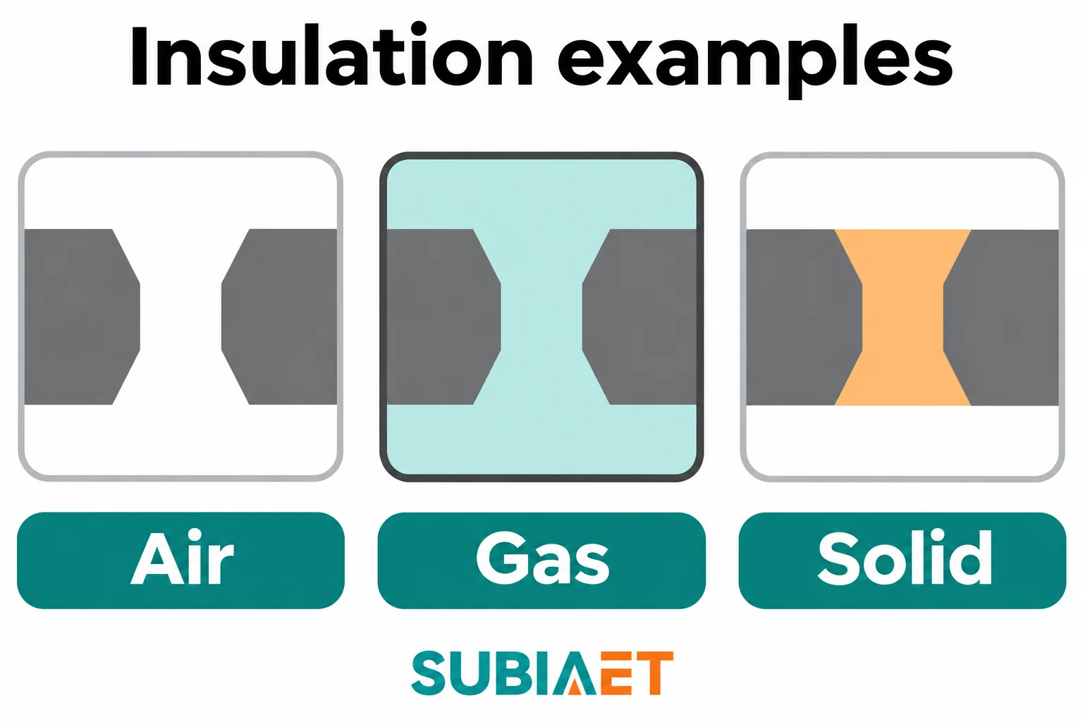
For medium-voltage assemblies, the material used to insulate live conductors from each other and from the enclosure is a distinct design parameter. Three material types appear in MV designs:
These insulation types describe the compartments and conductors inside the assembly. They are distinct from the interrupting medium used in the switching device, even though both choices must work together in the equipment design.
The device inside the assembly that actually breaks the arc when a circuit is opened can use a different medium from the main insulation. Vacuum interrupters — sealed chambers in which the arc is extinguished in near-vacuum conditions — are widely used in medium-voltage circuit breakers and are frequently combined with air-insulated or solid-insulated assemblies. The insulation medium and the interrupting medium are separate design decisions; a vacuum circuit breaker installed in an air-insulated panel means the assembly is air-insulated and the breaker uses vacuum interruption.
Circuit breakers and other functional units within a panel can be fixed (bolted in place) or withdrawable (mounted on a carriage that can be rolled or drawn out from the enclosure). Withdrawable arrangements provide defined connected, test or disconnected positions according to the equipment design. Whether a particular movement or maintenance activity is permitted with other sections energized depends on that design and the authorized procedure; withdrawability alone does not establish a safe work condition. The KYN28A-12 and KYN28-12 metal-clad switchgear listed on the SUBIA MV page are withdrawable designs; the HXGN-12 fixed switchgear is a fixed type. Fixed and withdrawable panels have different access and maintenance implications that belong in the selection conversation.
IEC 62271-200 is one standard that addresses specified AC metal-enclosed switchgear and controlgear assemblies, with its own scope restrictions and provisions for air-insulated and fluid-filled compartments. It is introduced here as an example of how standards address the assembly as a whole object with defined voltage and functional scope — not as a universal definition of medium voltage, and not as a compliance claim for any particular unit.
A realistic industrial or commercial facility connects several types of power distribution assemblies in sequence, and the name given to each assembly varies between the IEC world and the North American context. Reading a specification means knowing which names map to which functions in the applicable framework.
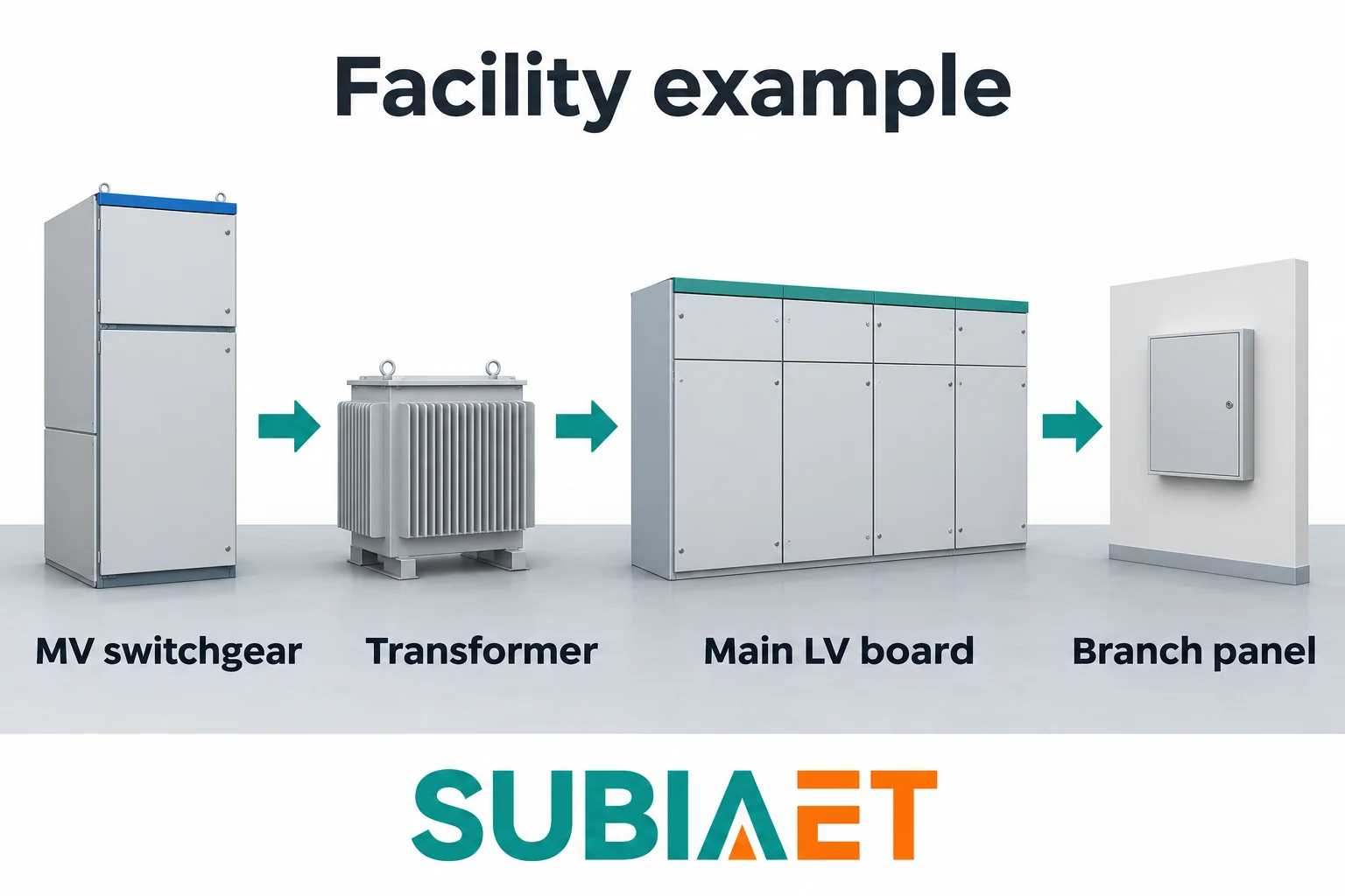
Consider an illustrative facility that takes supply from an MV network. Schneider Electric’s substation example illustrates the incoming and distribution functions:
MV switchgear — The facility receives power at medium voltage. The MV switchgear assembly at the facility boundary or in a dedicated switchroom performs incoming protection, measurement and feeder switching for the site’s MV circuits, which may include feeders to multiple transformers or to process loads connected at that voltage.
Distribution transformer — One or more transformers step the voltage down to low voltage for the bulk of the facility loads. The transformer itself is not switchgear, but it sits between the MV assembly and the LV distribution, and its overcurrent protection may be provided on the MV side, the LV side or both, depending on the design.
Main LV assembly — On the low-voltage side of the transformer, a main LV switchboard or main LV distribution board receives the full LV output. In this example it contains an incoming protective device, busbars and multiple outgoing feeder ways that supply different zones of the facility, with metering where specified. In IEC terminology this assembly may be described as a power switchgear and controlgear assembly covered by IEC/EN 61439-2. In North American practice, that function may be performed by a switchboard or by LV power circuit breaker switchgear, depending on the specified construction and product category. The system position alone does not determine which name applies.
Branch panelboards — Downstream of the main LV assembly, individual panelboards (or distribution boards) receive a single feeder and subdivide it into branch circuits for specific areas, equipment groups or floors. A panelboard can include overcurrent protection on each branch; it is not simply a passive junction. In North American practice, panelboards, switchboards and metal-enclosed low-voltage power circuit breaker switchgear are separate product categories, each with its own UL standard. These categories are not interchangeable, and a UL-category name does not map directly onto an IEC-assembly designation.
UL Solutions lists UL 1558, UL 891 and UL 67 for metal-enclosed LV power circuit breaker switchgear, switchboards and panelboards respectively. Eaton’s switchboard guide shows common switchboard arrangements.
The practical implication for a specification reader: when you encounter the term “main LV board” on a drawing, verify whether the specification refers to an IEC assembly type with a standard number, a North American switchboard category, or simply a functional label that could encompass either. The same logic applies to “MV switchgear” — verify voltage, insulation type, arrangement and applicable standard rather than assuming a category name alone defines the equipment.
For projects that combine MV switchgear, transformers and LV distribution within a single compact structure, SUBIA’s prefabricated substation overview explains how those elements are integrated.
If you are reviewing a distribution specification or preparing an inquiry for MV or LV switchgear, start with the system voltage, the required short-circuit withstand and breaking ratings, the insulation and arrangement type, and the applicable standard. The SUBIA MV switchgear page and LV switchgear page list the available series with their principal characteristics.
A circuit breaker switches a circuit and interrupts fault current within its ratings. An assembly can contain one or more breakers along with busbars, enclosures, connections and associated equipment. The assembly has ratings of its own.
A standard load-break switch handles its specified load-switching duty. A suitably rated breaker or fuse handles short-circuit interruption. Check the ratings and protective devices shown in the schedule.
Yes. Air can provide the main insulation in the panel while sealed vacuum interrupters inside the breaker interrupt current.
A panelboard may receive power from a feeder off the main LV assembly and distribute it to several branch circuits. The actual position and protective devices are shown on the single-line diagram and panel schedule.
