Request a Quote
Share the equipment and project requirements. If you need help selecting a model, describe the application.
Have drawings or specifications? Email [email protected] with your project reference.

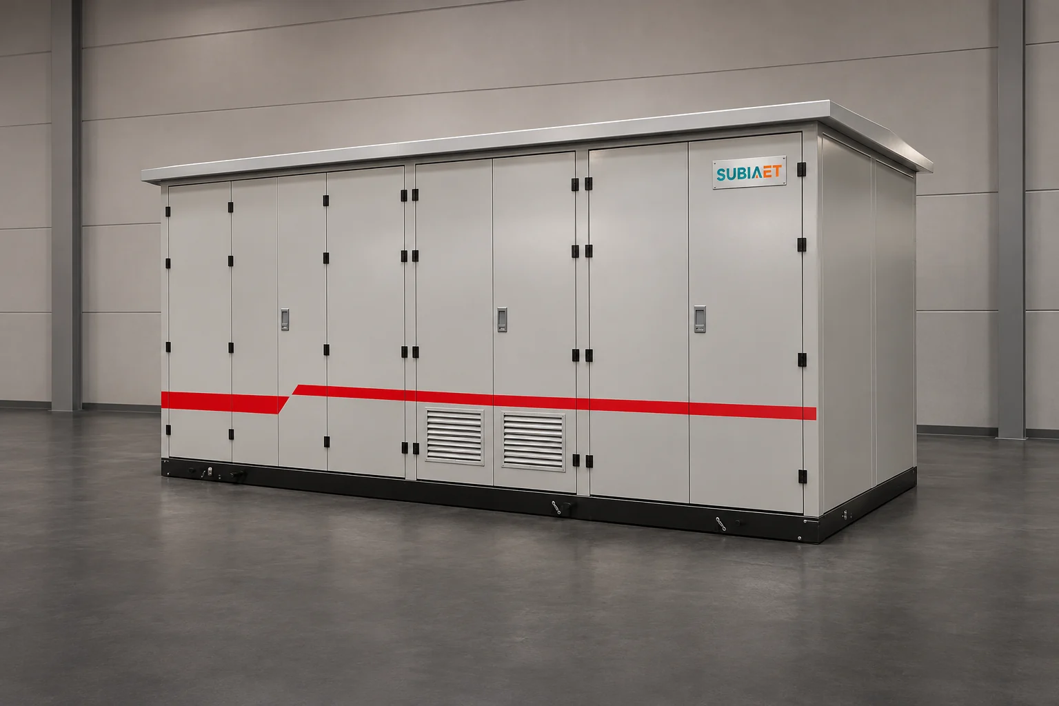
A transformer test report and a substation factory acceptance test answer two different questions. Treating the component report as an assembly release can leave part of the delivered package unverified. The transformer report says what was measured on one named unit. The packaged substation record says what was verified on an assembly in which that transformer is one component among several. Neither document substitutes for the other, and the gap between them — interconnections, auxiliary wiring, enclosure configuration, bonding, cross-device behaviour and the interfaces that only exist once the station is on site — is exactly where acceptance disputes live.
The practical task is to build a one-to-one mapping: every delivered object and every assembled function gets a record, and every record is traceable to a serial or a drawing revision. The sections below work through that mapping, then turn it into an inspection and test plan for one worked example.
A compact or kiosk substation is a single delivered package built from several objects that are each, in their own right, testable equipment. Depending on the ordered configuration, an MV/LV package can include:
Three identifiers make the paper trail work. The first is the commercial one: a contract line item, tag or equipment number that matches the purchase order. The second is the drawing identity: general arrangement drawing number and revision, single-line diagram, schematic and wiring diagram revisions, because a record without a revision can only be matched to a design in general terms, not to the design that was actually built. The third is the physical identity: transformer serial number from the nameplate, switchgear and LV board assembly serials, and the kiosk assembly number. When a report carries none of the three, it is a document about equipment in general, not about the equipment in the crate.
The evidence itself also comes in layers, and it helps to name them before arguing about any single test:
Standards reflect this split at the object level. IEC 62271-202:2022 applies, within its stated scope, to enclosed AC cable-connected prefabricated substations, and addresses service conditions, rated characteristics, general structural requirements and methods of test; the current public summary notes that high-voltage switchgear prefabricated substations fall within the scope revision. IEC 60076-1:2011 addresses single- and three-phase power transformers, including autotransformers, with stated exceptions and a cross-reference caveat for categories covered by their own standards. Read the two side by side and the division is explicit: one publication’s subject is transformer equipment, the other’s is the prefabricated assembly. What neither public synopsis gives you is a clause list, a test value or a compliance verdict for a particular kiosk, so the project edition, the contractual test schedule and the approved configuration remain the controlling documents.
Historic guide specifications show the same division from the procurement side. Eaton’s 2006 US guide specification for secondary unit substations lists transformer factory tests and secondary switchgear factory tests as separate blocks, with winding resistance and ratio among the transformer examples and the switchgear’s own wiring and function among the assembly examples; owner witnessing appears as an optional item and field startup is handled separately again. It is a historic ANSI/NEMA-referenced document, useful for the shape of the evidence, not as current guidance and certainly not as a list to paste into a modern specification.
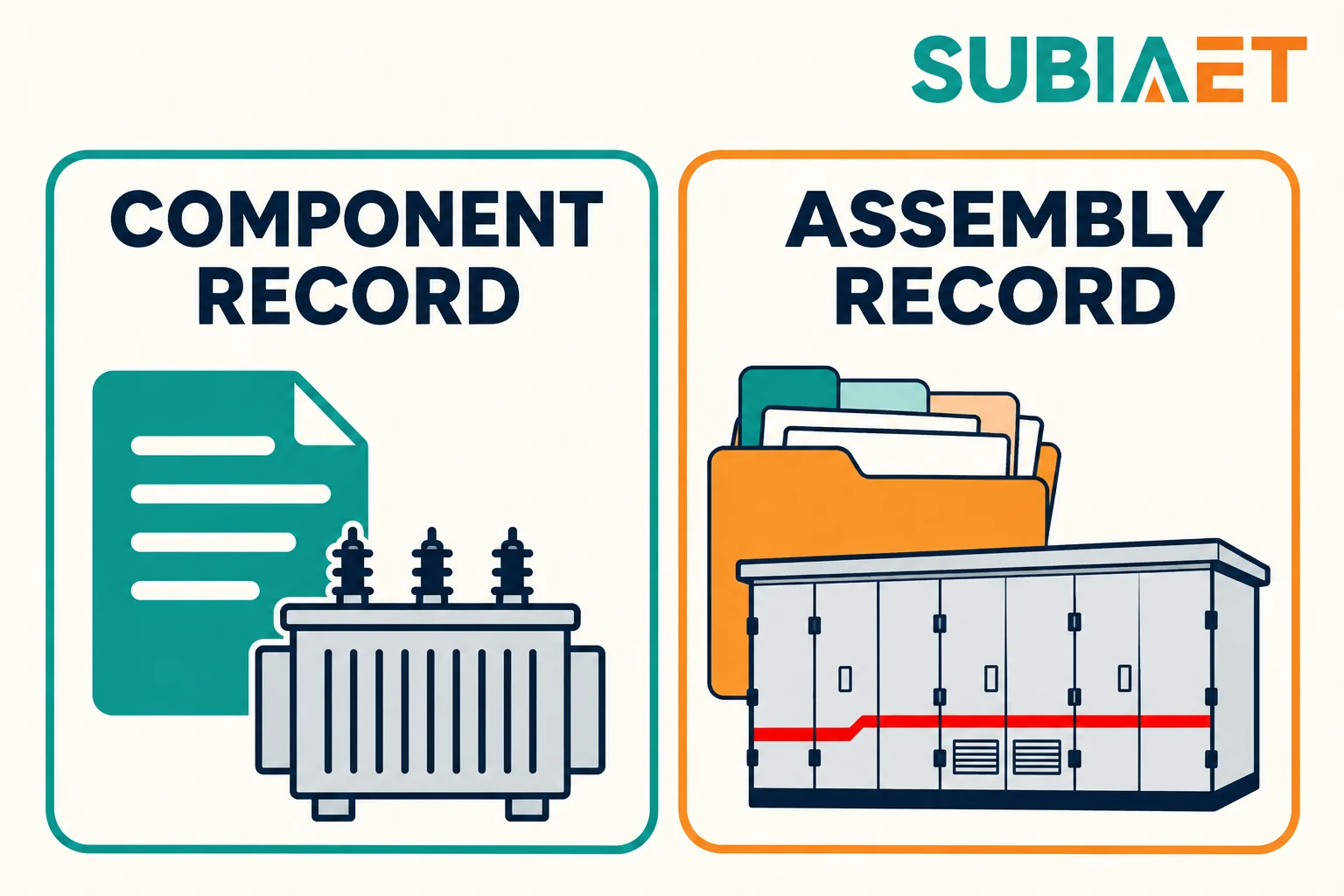
Take a routine report that matches the delivered transformer by serial number and by rating, and read what it actually says. For the unit it names, it records that a defined set of checks was performed, under stated conditions, and gives the measured results against the applicable criteria. Winding resistance and ratio are the classic examples found in component test schedules, alongside insulation-related and loss measurements depending on the specification. The report is evidence about that unit. Matching the serial establishes traceability. Review the actual results against the applicable criteria before closing that check.
That is a strong statement within its own boundary, and a weak one outside it. A transformer routine report says nothing about:
Use the applicable assembly, release or site record to cover those checks. The same logic applies to the other components. The MV switchgear and LV switchboard records each identify their own assembly and the checks actually documented, which may include dielectric, mechanical and wiring checks under the relevant procedure. Neither document, read alone, tells you how the two behave when their control circuits are interconnected inside the kiosk.
The practical consequence is a pairing rule: a component record is closed only when the physical identity in the report matches the physical identity on the equipment, and the component record is filed under the assembly in which that equipment is installed. A report with a mismatched serial is not a minor clerical issue — it is an unclosed item, because it is evidence about a different object.
For the internal structure of a routine report — what each block of measurements is for and how to read the values before shipment — see the guide on how to read a transformer routine test report before shipment. This article stays at the level of scope: which object the report covers, and where its coverage stops.
Assembly-level checks exist because the kiosk creates relationships that no component test can see. Four groups help a buyer map the required evidence for the ordered package.
Internal power connections. The MV connections between the switchgear and the transformer, the LV connections between the transformer and the LV board, and any internal cable or busbar runs are checked against the approved drawings and project procedure. Relevant checks may include conductor and phase identification, terminations, clearances, support, specified tap position and documented connection checks. An owner specification can reasonably ask for evidence of the HV interconnection specifically, because that connection is made in the works and is invisible after the doors are closed.
Auxiliary and control wiring. Point-to-point verification of the wiring between devices against the approved schematic: auxiliary supply distribution, heater and lighting circuits, and the control and signalling cores that link protection, switching devices and terminal blocks. The wiring check establishes correspondence with the drawing and its stated test scope. Record the schematic revision, method and actual result, with the person and date behind the sign-off.
Controlled behaviour across devices. Where the scope includes it, functional checks that exercise the interaction: a local trip command operating the intended device through the intended path and producing the intended indication; interlocks preventing an unintended sequence; status contacts following the device they monitor; alarms appearing where the schedule says they should. For these functional checks, record the stimulus applied, response observed and acceptance criterion, plus any measured values the procedure calls for.
Enclosure and earthing. Bonding continuity between the parts that must be bonded, earthing bar continuity and its connection points, door and panel fit, ventilation openings built to the approved arrangement, cable entry sealing arrangement, and the condition of internal partitions that maintain separation between compartments.
An attributed owner example shows the intended structure. Sydney Water’s specification for prefabricated (kiosk) substations, DOC0020 v5, keeps component requirements, station type reports, witness opportunities, routine factory tests, factory report contents and site testing as separate subjects. Its station routine examples include HV interconnection evidence, auxiliary and control tests, functional checks and correct wiring. It asks for separate factory and site inspection and test plans with applicable procedures, acceptance criteria and possible witness or hold points, and it expects the completed plan, records and defect list inside the factory report. That is a specific Australian owner requirement referencing AS 62271.202 — use its evidence structure as an example and take the applicable thresholds, deadlines and detailed test scope from your own project.
The distinction that resolves most confusion here is between a named assembled configuration and a set of independent component reports. The assembled configuration is the specific combination of enclosure revision, equipment arrangement, wiring and settings that was built. Evidence for that configuration is produced against the assembly, by the assembly’s identifier. Component reports support the assembled record; they do not constitute it.
Three kinds of evidence are routinely confused, and a fourth is often forgotten.
Type (design) evidence demonstrates that a design satisfies a requirement, established on a representative arrangement rather than on every unit sold. Its value depends entirely on applicability: the delivered configuration must match the tested arrangement in the characteristics the evidence actually depends on. A type report is not a certificate for a product family in perpetuity; it is evidence about an arrangement, usable where the reviewer establishes that the delivered arrangement and duty are within the evidence’s supported scope.
Routine records are per delivered unit. They document the checks performed on the specific object identified in the report. They carry serial numbers and dates, and they are the reason the pairing rule above matters.
The project FAT is an acceptance activity on the actual package: the delivered assembly is checked against procedures and criteria agreed for the project, with witnesses present where the contract requires them. FAT is where the assembly-level groups from the previous section are demonstrated and recorded.
Site verification comes afterwards and covers what the factory cannot: installation quality, external cable connections, the real supervisory and remote interfaces, and energization-related checks.
Two supporting definitions make the rest of the article usable.
An inspection and test plan (ITP) is a planning document. For each object or function it states the reference document and revision, the acceptance criterion and the procedure that will be used, who performs the check and when, whether the step is a witness or hold point, and what record results. An ITP is not a test method; it points at test methods. Confusing the two produces plans that list activities with no criteria, or procedures with no ownership.
A witness point is a step the buyer or their representative is invited to observe. A hold point is a step that cannot proceed to the next stage until the designated reviewer has released it. Both are created by the contract and the agreed procedure, not by good practice in the abstract. If the agreement permits a FAT without customer attendance, keep the same applicable results and document how they were reviewed and accepted.
Finally, the smallest unit of evidence: a report cover sheet is not a test result. A cover sheet identifies equipment, standards referenced and date; the result is the measured value or observed behaviour, with its conditions and the criterion it is compared against. If result pages are missing, leave the applicable result review open.
Consider a fictional order for a kiosk with an MV ring-main unit, a distribution transformer, an LV distribution board, auxiliary circuits and a planned link to a remote supervisory control and data acquisition (SCADA) system. The station is integrated and assembled at the supplier’s works, shipped as one package, and installed by a site contractor under the owner’s site procedures. The ITP below is written for that order; the identifiers are the mechanism, not the values.
| Object or function (tag / drawing revision) | Criterion and procedure source | When and by whom | Record and status |
|---|---|---|---|
| Transformer, tag T1; serial from nameplate; rating per approved datasheet | Contract transformer test schedule; supplier routine test procedure at the revision listed in the contract | At the transformer works, before packing; supplier QA | Routine test report, serial matched to nameplate; closed |
| MV ring-main assembly RMU-1 and LV board LV-1; assembly serials | Assembly routine checks per contract and the switchgear standard invoked by the specification; works test sheets | At each component works, before delivery to the integration bay; component QA | RMU-1 report received and matched; LV-1 report received but the serial on the report does not yet match the delivered board; open |
| Internal assembled wiring and local trip/status function; approved schematic and functional schedule revisions | Approved schematic and functional schedule; project FAT procedure | In the integration bay during FAT; supplier, with buyer witness if agreed as a witness point | Signed FAT record with wiring verification; local trip/status passed. Record drawing markups separately for closeout. |
| Enclosure ventilation arrangement; GA drawing as tested versus as built | Applicability of existing design evidence to the delivered arrangement | Engineering review before FAT release; supplier engineering with buyer review | Revised GA drawing issued; applicability statement from the responsible engineer pending; row on hold |
| Simulated external signalling interface; point-to-point schedule | Signal list and point-to-point schedule; FAT procedure for simulation | In the integration bay during FAT; supplier | Simulation log marked as simulated; passed as simulation only |
| Site end-to-end interface verification; site ITP | Site ITP criteria and approved settings; field procedure | After installation; site contractor, owner witness as specified | Site ITP sheets; planned, not started |
Three statuses are doing different work in that table, and the difference is the point. Closed means the record exists, matches the equipment identity, and meets its criterion. Open or on hold means a record is missing, mismatched or unsubstantiated — nothing downstream should treat the row as satisfied. Planned means the check legitimately belongs to a later stage and has an owner and a criterion waiting for it; that is not a defect, provided the plan says so before release rather than after.
Note also who acts. The supplier’s integration QA owns the FAT records and supplier engineering owns the design-review response in this example; the site contractor owns the site row, executed under the owner’s site procedures. Assigning a site activity to the supplier by default is how rows quietly become permanent open items.
Now change one thing. The ventilation arrangement on the enclosure is revised: the tested layout had its openings low on the panel, and the delivered arrangement relocates them. Nothing else about the enclosure changes — the same doors, the same internal partitions, the same equipment arrangement inside.
The questions to ask are ordered, and the order matters.
First, what was the earlier evidence about? Design evidence is attached to an arrangement and to the conditions under which it was established. If the ventilation arrangement formed part of the tested configuration, then the tested configuration and the revised one are no longer identical, and the difference has to be characterised rather than ignored. If the openings were not part of what the evidence depended on, that conclusion also needs to be stated, by someone with the design responsibility to state it.
Second, compare revisions side by side. Tested layout against revised layout, at the same scale, marking what moved. In the ventilation case: opening position and area, free area through the panel, any change to internal airflow paths around the transformer, any effect on the enclosure’s structural or ingress arrangement, any effect on compartment separation.
Third, ask for a substantiated position, not an assurance. There are several legitimate outcomes, and they are not interchangeable:

What is not acceptable in any of those outcomes is assumed equivalence. A revision that looks minor on a drawing is not automatically minor to the evidence, and a claim that everything still applies is worth exactly as much as the reasoning behind it. Equally, do not overcorrect: not every change forces a full re-run of every test, and treating a drawing revision as an automatic re-test trigger wastes the project’s schedule without improving the evidence.
Keep the item visible while it is open. In the worked example the ventilation row is on hold at design review, the punch item has an owner (supplier engineering) and a required response (a documented applicability position), and the consequence is explicit: the row cannot be closed until that response is reviewed and accepted. Whether the hold also stops shipment depends on the hold point agreed in the contract — which is a decision recorded in the ITP, not an assumption made at the end of the project.
Factory testing may have a boundary where field equipment or the remote SCADA system is absent. Either the remote system is not yet available, or it exists but is not connected to this package, or the field devices that generate the signals are on the site, not in the bay. Where agreed, a simulation can exercise the relevant part of the package’s logic and wiring. Record exactly which terminals, signals and devices were involved.
Simulation is genuinely valuable and must be labelled as what it is. A project automation verification example published in ABB Review makes the distinction concretely across a customer project: factory verification including simulation of absent equipment, a customer-witnessed FAT, then site testing with the real switchgear and remote-system connections, then site acceptance and handover. The important line in that sequence is that a simulated external link and actual end-to-end behaviour are different evidence. It is a bounded vendor example for one project-specific automation system; it says nothing about current ABB or SUBIA services, protection settings or any particular communication standard, and it does not define which checks a given project needs. Its structure, though, is generally sound.
Three categories get muddled in practice, and separating them fixes the handover:
Actual local checks. A signal is generated at its real source inside the package — an auxiliary contact on a real device, a real terminal — and observed at the package’s own terminal block or local indication. There is no simulation: the device, the wiring and the observation all exist. This is factory evidence and can be closed in the works.
Simulated checks. The response of an absent party is emulated to exercise the package’s logic. A simulation result applies only to the parts actually exercised. Wiring up to a terminal is covered only if it was in the test path. A simulated pass can close the specified simulation row while real field connections remain open for the site check.
Site end-to-end verification. The real source, the real path and the real destination are all present. The check demonstrates that a change at the field device produces the intended indication or control at the remote system, through the installed cabling and the configured communication path.

In the worked example, the simulated row is closed as simulation only, and the external supervisory and field connections sit in the site ITP for actual end-to-end verification with an owner, a criterion and a record. Two practical points keep that honest. First, the simulation log should say, in the record itself, which parts of the path were real and which were emulated — a reader two years later cannot reconstruct it from a tick box. Second, the site row should be written at the point of release, not at the point of discovery: an interface that was never simulated, never listed and never assigned is the one that turns into a commissioning argument.
A release package that can be defended does not need to be large, but it needs every item in it to be identity-bound. A workable closeout list:
Two separations deserve their own line in the release meeting. Release for shipping is a logistics and configuration decision: the package is built to the approved configuration, the factory items are either closed or carry an approved disposition, and the shipping configuration and any post-transport inspections or reconnections are documented. Site acceptance and energization approval is a different decision taken later, on different evidence: installation checks, external connections, end-to-end verification and the owner’s energization procedure. Signing a shipping release does not sign a site acceptance, and a FAT certificate is not an energization permit.
For the boundaries that have to be settled before any of this can be planned, two earlier guides in this series are the natural next reading: the renewable compact station RFQ checklist covers what to define about interfaces and ownership before order, and pad-mounted transformer vs compact substation covers what is actually inside the supply boundary being accepted. For the equipment itself, the prefabricated substation range shows current configurations, and components and power flow explains how the internal objects relate to one another.
No. The routine report is evidence about one named transformer unit and the checks specified for it. A substation FAT is evidence about the assembled package: internal power connections, auxiliary and control wiring, behaviour across devices, bonding and the agreed functional checks. For a package that includes the transformer, file its report alongside the required assembly evidence. Check that separate evidence covers the required interconnections and cross-device functions before accepting the assembly.
Only to the extent that the delivered arrangement matches what the evidence was established on. Type evidence attaches to a configuration and to the conditions of the test, so reuse is an applicability judgement, not a filing decision. When the enclosure layout, internal arrangement, ratings or equipment combination change, the responsible engineer should state which characteristics the evidence still covers and how any gap will be closed. Reuse is often entirely justified; it just requires the reasoning to be written down rather than assumed.
No. Witness points and hold points are created by the contract and the agreed procedure. One owner may require attendance at defined factory stages and hold release until review; another may accept a documentary FAT with no attendance. Neither approach is universally correct. What matters is that the points are agreed before the work starts, written into the ITP, and recorded as attended or released — a hold point discovered after the fact cannot be retroactively witnessed.
It should not be, because it demonstrates something different. A simulation exercises the part of the package and signal path named in the test record while the absent equipment is emulated. The end-to-end behaviour — real source, real path, real destination — only becomes observable after installation. A simulation is worth doing and worth recording as a simulation; the interface it covers should remain an explicitly planned site activity with its own criterion and record, rather than being counted as already verified.
Yes, when the contract’s factory release conditions are met and the outstanding site checks are explicitly assigned. Release for shipping is a factory-stage decision about configuration and closure of factory items; site acceptance and energization approval come later, on installation evidence, external connection checks and end-to-end verification. The two decisions should be recorded separately, with the deferred items listed and owned at the point of shipment. Collapsing them into one signature either blocks logistics unnecessarily or, worse, allows a site-dependent check to be treated as already done.
