Request a Quote
Share the equipment and project requirements. If you need help selecting a model, describe the application.
Have drawings or specifications? Email [email protected] with your project reference.


The transformer at an EV charging site is sized from the apparent power the charging equipment draws at its AC terminals, plus everything else fed from the same transformer, evaluated over time in normal operation and under credible failure of any load management the design relies on. The worked example compares 500 and 630 kVA candidates as conditional screens. Final selection also depends on the site supply and equipment limits.
Four different quantities get used interchangeably in early planning conversations. Each answers a different sizing or operating question.
DC output kW is the real power delivered at the vehicle inlet downstream of the charger’s power conversion. Real AC input kW is what the cabinet draws at its AC terminals to supply that output, conversion losses and any auxiliaries included at that boundary. Apparent AC input kVA describes the AC supply loading on an RMS voltage and current basis. Winding current, harmonic content and thermal conditions affect transformer heating. kWh measures energy delivered or drawn over time and helps check whether charging schedules can meet departure requirements.
A manufacturer’s stated input kVA and input current at the actual supply voltage and configuration is the primary sizing input. Reconstructing apparent power from DC kW, an efficiency figure, and true power factor is a fallback for the screening stage, and it is only valid when all three inputs describe the same declared operating point and electrical boundary.
For a balanced three-phase load, the arithmetic is:
S (kVA) = √3 × V (line-to-line, volts) × I (RMS line current, amperes) ÷ 1000
A documented example shows why the separation matters. The ABB Terra 94/124/184 UL product guide lists, for the Terra 184 column, a maximum DC output of 180 kW, with two simultaneous 90 kW outputs shown as an alternative — and separately, a nominal AC input of 230 A and 192 kVA at a specified 480Y/277 V, 60 Hz supply. The same series lists power factor above 0.96, current THD below 5%, and efficiency of 95%, with a footnote tying those figures to nominal output conditions. At the stated nominal line-to-line voltage and current, the balanced calculation is:
√3 × 480 V × 230 A ÷ 1000 ≈ 191.2 kVA
The calculated 191.2 kVA is close to the table’s published 192 kVA. Use the supplier’s stated rating for that configuration and confirm the input limits over the project’s actual supply range.
If the supplier gives only DC kW and efficiency at a matching operating point, divide DC kW by the corresponding AC-to-DC efficiency to estimate real AC input kW. Then divide that input by true power factor to estimate kVA. Confirm which auxiliaries the efficiency already covers and add only separate loads at the applicable boundary. A maximum DC output, nominal AC rating and minimum power factor from different catalog fields do not establish one operating point.
Two traps recur.
The first is mixing rows. A datasheet may state an input voltage range such as 480Y/277 V with a tolerance band, and quote current at nominal voltage only. Multiplying the bottom of the voltage band by the nominal current can misstate the input. A charger may draw more current to hold power, or reduce output at lower voltage, depending on its limits. Pair each current with the voltage and operating condition it describes.
The second is treating an AC charging port as if it had a fixed draw. For Level 2 AC equipment the station controls the supply to the vehicle. Its actual draw depends on the vehicle’s onboard charger, which may draw less than the pilot signal’s advertised current depending on the vehicle, state of charge, and temperature. The circuit and equipment ratings set limits. Use the expected vehicle mix to estimate operating demand, and check the equipment supply and branch circuit separately against the applicable requirements.
For transformer apparent power, reactive power, and power factor fundamentals behind this arithmetic, see why transformers are rated in kVA.
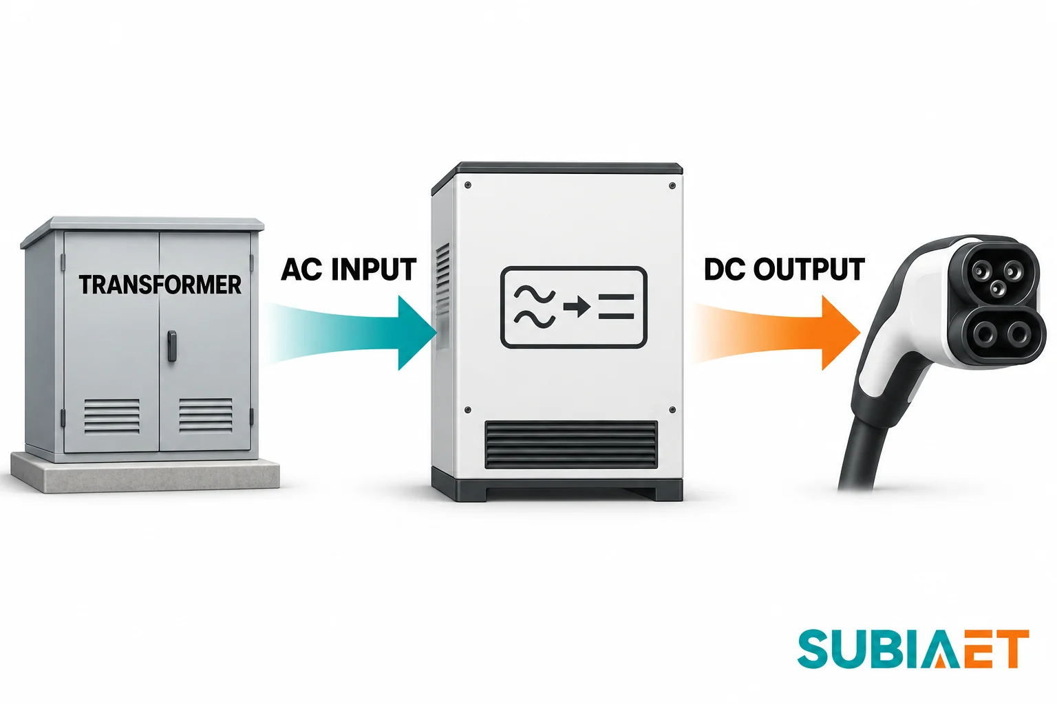
Before any arithmetic, draw the boundary. A typical DC site runs: utility service → site transformer → AC bus or switchboard → one or more power conversion cabinets → dispenser or integrated connector positions → vehicle inlet. Identify which AC loads the transformer actually supplies and where each rating or measurement is taken.
With shared power blocks, the connectors are delivery points. A cabinet that supports simultaneous sessions can split its total DC output between vehicles. Count the independently AC-fed cabinets or blocks and identify their stated AC input. Check which cabinets and power modules can run together at full output.
The U.S. DOE and National Laboratory of the Rockies EVSE characterization study is useful precisely because it keeps the boundaries visible: its records distinguish AC cabinet input, dispenser auxiliary AC, and DC vehicle inlet as separate measurement points, and it reports simultaneous sessions at both ports with separate AC input and DC output records. That three-way split is the habit to carry into a design review — each of those three electrical boundaries can appear on a drawing. The energy delivered at the DC outlet is already represented upstream in cabinet AC input. Add auxiliary AC supplied separately only if it draws from the same transformer.
Auxiliaries then need a deliberate inclusion decision:
The inclusion list is model-specific. What a given vendor’s cabinet datasheet folds into its stated input kVA holds for that model and configuration only; another cabinet with the same output rating may require a separately supplied cooling circuit. Read the note under the table rather than assuming equivalence across brands.
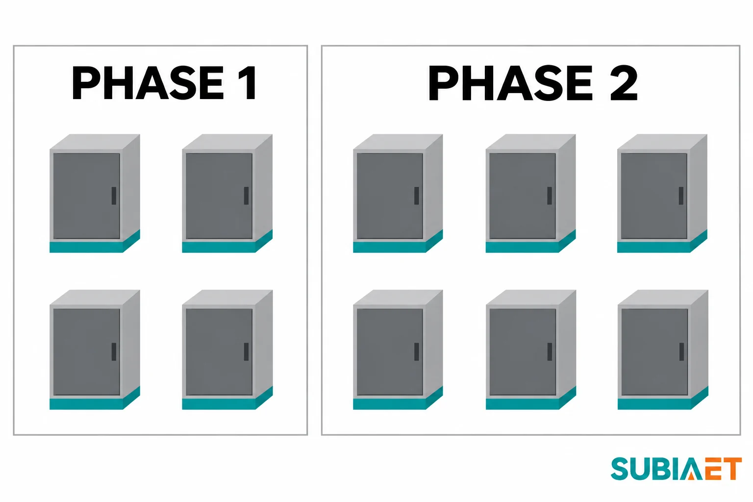
Expansion is the other counting error. A phase-two cabinet added later adds a new AC load if it is connected to the same transformer. If the transformer, switchboard bus, and feeder are sized for phase one only, adding cabinets may require a service or equipment upgrade.
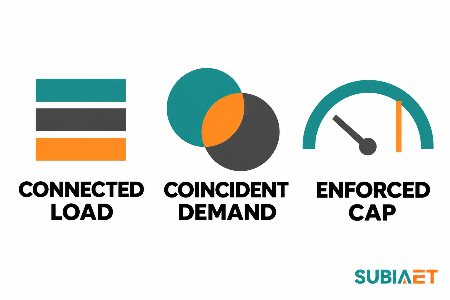
Connected load, coincident demand, and enforceable cap answer three different questions, and a site needs all three.
Connected load is the arithmetic sum of everything that could draw at once — every cabinet at its stated AC input, every auxiliary, every building load. It is an upper screen. Use it to screen the connected equipment before relying on load management. A failed control may produce a different demand, which requires its own credible case.
Coincident demand is the combined load at the same time or over a defined demand interval. It follows time profiles: when vehicles arrive, how long they stay, how much power each takes as state of charge rises, when they must depart, what the building is doing at that hour, and how ambient temperature shifts both HVAC load and vehicle charging behaviour. It can be forecast from arrival and dwell assumptions or measured for the site or estimated from comparable operating data with the differences stated.
Enforceable cap is a limit the equipment will actually hold, at a defined measurement point, under defined failure conditions. Use it as a design input only within the documented and accepted scope of the control and its fallback.
There is no universal diversity factor to apply between them. A fleet depot with concentrated returns and departures has a different charging profile from a highway plaza with varying arrivals. The DOE AFDC infrastructure planning material makes this concrete: it describes site planning around the coincident total of charging and facility loads, and a workplace rollout that used measured site limitations together with charge completion requirements to allocate power — rather than applying a rule-of-thumb factor. The same material points at service, panel, and transformer capacity as the constraints to check early, alongside early utility engagement.
Departure-driven energy is a separate check for a managed site. Divide the energy the vehicles need by the available charging time to screen the average delivered DC power. If the vehicles need 900 kWh delivered between 18:00 and 06:00, the 12-hour window requires 75 kW average delivered DC power. The corresponding average AC input also includes losses and any relevant auxiliaries. Check individual arrival and departure windows and vehicle power limits. The site can meet the aggregate energy requirement over the full window and still miss an early departure.
Equipment and utility constraints sit outside the demand calculation and must be tracked separately. The transformer has its own thermal limit; the utility feeder and service have theirs; the switchgear bus and the cables have theirs. The binding constraint is whichever is reached first, and adding capacity at one layer does not move the others. Phase loading shares exactly this boundary: a site whose aggregate kVA looks comfortable can still have one phase exceeding its applicable current limit when loads are unevenly distributed.
A utility application workflow makes the documentation requirement visible. The Southern California Edison Rule 29 EV infrastructure process asks for a site plan, charger cut sheets, a load schedule and a single-line diagram for engineering. Its optional pre-assessment calls out transformer, switchgear and port locations on the site plan and does not reserve load. It is one utility example. Confirm the applicable application, study and reservation process for the actual site.
A charging allocation scheme and an accepted transformer input constraint are not the same thing, and confusing them is the most expensive error in this whole exercise.
A commercial allocation decides who gets how much power and when — round-robin sharing, first-come priority, departure-time weighting, tariffs. It is a fairness and service policy. An accepted input constraint is a defined AC limit at a named measurement point, with approval from the electrical designer and the relevant utility or authority where applicable. The operator confirms the charging service it permits. Credit the limit only for the operating and failure cases it covers.
The evidence you need before crediting a cap is specific:
The Schneider Electric EcoStruxure EV Charging Expert dashboard documentation illustrates the fields that make verification possible at handover: reserved, allocated, and measured consumption where a meter is assigned; charging phase configuration and selection; setpoint versus measured consumption; firmware version; and degraded current. Use the actual phase readings and configurations in the commissioning record. A displayed setpoint is distinct from a measured response and does not establish acceptance.
Listing scope needs the same discipline. The ChargePoint CPF50 site design guide describes UL 916 Energy Management listing and real-time network communication for that North American AC station, and distinguishes the station circuit from the connection to a given supply and equipment phase arrangement. That statement covers that product; it says nothing about a DC cabinet’s controls, a third-party energy management system, or the validity of a specific loss-of-communications behaviour.
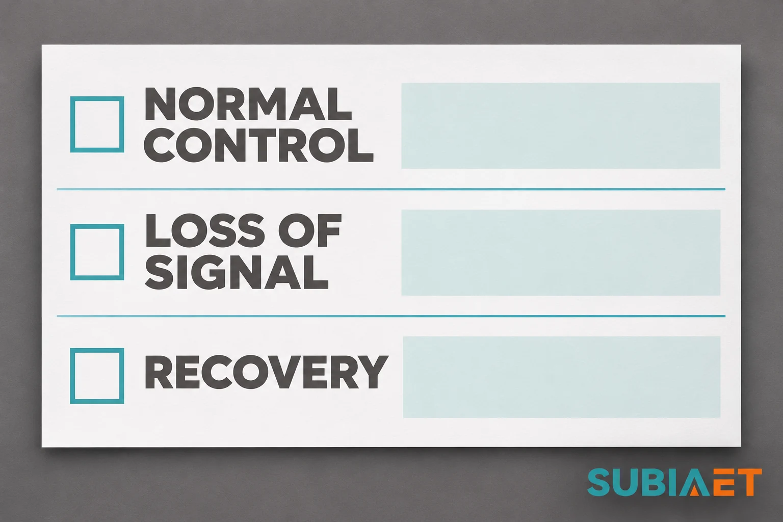
The final step is a witnessed check under the approved commissioning plan. Record the controller and meter revisions, maximum observed current or kVA at the required boundaries, response time, and how the site behaves in each specified failure and recovery state. Leave the cap uncredited in any design case whose required limit has not been substantiated.
Transformer sizing is not finished when the kVA comparison passes. Check the charger’s supply limits against the combined utility, transformer and feeder characteristics and the proposed loading.
Voltage and the supply envelope. Obtain the selected charger’s input voltage window and tolerance. Transformer impedance, feeder impedance, and the voltage drop during a load step from idle to full output jointly decide whether the terminals stay inside that window. A site can pass the kVA check and still see low voltage at the charger terminals when several units increase load together. Off-load to full-load voltage regulation, tap settings, and the utility’s own voltage profile all enter this calculation. Frequency, phase rotation, and earthing arrangement are the other envelope items — some equipment specifies a particular source grounding configuration, so verify compatibility against the approved design.
Phase balance. Some sites use single-phase AC stations or loads that do not draw equally on all phases. Review each phase’s RMS current and the neutral current where a neutral is present and carries load. Aggregate kVA can hide a heavily loaded phase.
Harmonics. The input current spectrum depends on the charger power electronics and operating point. The DOE EVSE characterization study shows exactly this: quasi-steady measurements from the named equipment record efficiency, power factor, and AC current distortion all varying with operating condition. A single THD figure taken at rated output does not describe part-load operation or an entire site. A higher distortion percentage at light load does not by itself imply higher absolute harmonic current. The ABB series’s “current THD < 5%” statement is a product claim at nominal output conditions for that configuration — it is not a site limit, a transformer derating basis, or a guarantee about aggregate distortion when several units run in parallel.
There is no universal harmonic limit or derating factor to apply. The defensible approach is to obtain the actual harmonic spectrum from the equipment vendor across the expected operating range, study how the applicable harmonic orders combine for concurrent equipment and other loads, and check the resulting duty against the transformer’s thermal capability. Review the utility’s power-quality requirements separately at its specified assessment point. Where distortion is significant relative to the load, a special-design transformer or a derated standard unit may be warranted — but that decision follows the spectrum, not a rule of thumb.
Thermal environment. Winding temperature depends on ambient temperature, enclosure ventilation, solar gain, harmonic duty and load duration as well as magnitude. An outdoor pad in full sun, a ventilated enclosure with restricted airflow, or a cabinet cluster with recirculating hot air can all reduce usable capacity below nameplate. Use the project’s credible sustained ambient and loading profile on the transformer supplier’s stated thermal basis.
The common thread is that all four checks need a study rather than a lookup. For the transformer-side thermal treatment of harmonic duty, see when to review derating or a special design.
The choice between one larger transformer now and a staged build is a comparison of accepted duty across both phases, not a matter of adding a standard margin.
Start with what the transformer must carry in each state. Phase one connected load and phase one managed normal load are different numbers. So are phase two connected and phase two managed. Add the abnormal cases: loss of the load management controller, loss of a meter, a cold start with all connectors occupied, and any operating mode the operator intends to permit. For each, record the magnitude, the duration, and whether it is a normal-duty or emergency-duty condition. The transformer’s response depends on prior loading, cooling, ambient conditions and duration. Any temporary overload must be evaluated on the accepted transformer loading basis.
Then check the layers around it. The utility’s service rating and its own equipment may cap what you can actually draw regardless of transformer nameplate. Switchgear bus rating, breaker frame and trip settings, cable ampacity, and voltage drop all have their own limits, and any of them can be the binding constraint. Civil space matters more than it appears: pad footprint, clearances, enclosure access, cable trench capacity, and the space reserved for a second unit all get decided early and cost real money to change later.
On the utility side, distinguish a capacity indication from a capacity commitment. The SCE Rule 29 material draws exactly this line — a preliminary indication of available capacity is not a load reservation, and the workflow depends on AHJ service approval and the final installed port count. That distinction is worth carrying into any utility conversation: record what the utility has reserved, on what conditions, and what must be rechecked before future energization.
The practical comparison usually comes down to four options:
There is no universal spare-capacity percentage. The right margin comes from the specific expansion trigger — a signed phase-two lease, a fleet commitment, a funding milestone — and from the lead time for the equipment you would need to add. A staged approach makes sense when phase two is uncertain in timing but plausible in scale; a single larger unit makes sense when the second energization would be disruptive or when the lead time exceeds the window between the decision and the need.
General treatment of load growth and margin selection for non-charging facilities is covered in transformer sizing for factory expansion, which uses the same duty-case logic.
Fictional planning example. Cabinet figures, candidate transformer nameplates and load caps are assumptions for this site only.
One balanced three-phase site. Four phase-one DC cabinets each have two connectors sharing one 120 kW DC output block. Each block is specified in this example for up to 132 kVA AC input on the stipulated supply, inclusive of its internal auxiliaries. Separate non-charging apparent load is 50 kVA when coincident in phase one. In phase two add two identical cabinets and model 65 kVA concurrent non-charging load. Arithmetic sums of coincident kVA magnitudes are used as conservative planning screens.
| Case | Basis | Arithmetic sum | Reading |
|---|---|---|---|
| Phase one, connected screen | 4 × 132 kVA charger inputs plus 50 kVA concurrent site load | 578 kVA | 500 kVA fails this screen. A 630 kVA candidate clears the arithmetic comparison only. |
| Phase one, proposed managed normal | 350 kVA EV-side AC input cap plus 50 kVA | 400 kVA | A 500 kVA candidate clears this arithmetic comparison only if the applicable constraint is documented and accepted. |
| Phase one, provisional degraded case | One tested communications-loss mode limits EV input to 280 kVA plus 50 kVA | 330 kVA | This one illustrative mode is below 500 kVA; meter failure, restart and other required cases are still open. |
| Phase two, connected screen | 6 × 132 kVA charger inputs plus 65 kVA concurrent site load | 857 kVA | Neither the 500 kVA nor 630 kVA candidate clears this connected-load screen. |
| Phase two, same proposed managed normal | 350 kVA EV-side cap plus 65 kVA | 415 kVA | Review charging service at six cabinets and verify the constraint and degraded behavior again. |
| Shortlist and release | Choose by accepted present and future duty and network/thermal reviews | 500 kVA remains conditional with accepted constraints. 630 kVA only clears the phase-one connected arithmetic screen. | Confirm utility and protection reviews, actual charging service and fallback before approving nameplate and civil expansion. |
Reading the table in order matters. The first row shows why four cabinets with eight connectors still represent four shared power blocks, and the arithmetic screen lands at 578 kVA — above 500 kVA and below 630 kVA. The second row shows the effect of the proposed managed cap: 400 kVA fits a 500 kVA candidate, but only against a 350 kVA EV-side constraint that is documented and accepted, not merely configured. The third row shows one tested communications-loss mode. The other required degraded cases remain open.
The phase-two rows are the ones that usually get skipped. Connected load at six cabinets is 857 kVA, which no candidate on the shortlist carries. The managed normal case at 415 kVA is comfortably inside 500 kVA as arithmetic, but it requires the same 350 kVA cap to hold across six cabinets rather than four, which is a charging-service question as much as an electrical one: more concurrent demand may leave less power for some sessions. Review the allocation and energy by departure with the operator.
The arithmetic sum of coincident apparent-load magnitudes is a planning screen. It is not a calculated aggregate metering result, it does not account for phase imbalance, and it does not prove thermal adequacy. It tells you which candidates are worth studying further.
Before placing the order, assign each design input an owner and an accepted basis. Put the later site verification and energization hold points into the procurement and commissioning plan.
From the EVSE vendor, per model and per configuration:
From the control supplier: the measurement point and units, whether the limit is aggregate or per-phase, configured response time, the degraded default for each communication path, cold-start and recovery behaviour, manual override policy, expansion headroom, and a witnessed test procedure.
From the utility, request available service capacity, whether an indication is preliminary or a binding reservation, utility metering and protection requirements, and the applicable application and energization sequence. Confirm code, permit and inspection acceptance with the authority having jurisdiction, as applicable. Requirements vary by utility and jurisdiction.
From the electrical designer: the single-line diagram, load schedule, per-phase allocation, protection coordination, feeder sizing and voltage drop, earthing design, short-circuit study, and the transformer thermal basis with site ambient.
From the operator: arrival and dwell patterns, energy required by departure, tolerance for reduced charging speed when the cap engages, and the expansion trigger that will start phase two.
Before order release, freeze the electrical package, specify the accepted control design and fallback requirements, and identify the required feeder and utility studies. Before relying on the cap in service, obtain the specified witnessed commissioning results for the applicable normal and degraded cases. Record the operating review and release trigger before expanding to phase two.
If the project is at the stage of establishing site interfaces and sector-specific requirements, the infrastructure and public facilities application overview provides useful context on how charging, buildings, and utility connections come together.
No. Connector kW describes DC power at the vehicle inlet, downstream of conversion losses and auxiliaries, and a connector rating does not show apparent AC input or how output is shared. Two sessions on a shared power block draw from the same block capacity. Start from the vendor’s stated AC input kVA and current at the actual supply voltage, count independently powered cabinets or blocks, and add the separately supplied site loads. Use DC kW only as a cross-check on whether the stated input is physically plausible.
It can, but only against a constraint that has been documented and accepted for the design’s normal and degraded states. The difference between a commercial allocation policy and an enforceable input limit is decisive: the first changes who charges fast, the second bounds the current at a named measurement point. Before crediting any reduction, require the measurement location and units, the per-phase versus aggregate basis, the response time, the degraded default for loss of controller, meter, network, and charger communications, and a witnessed test of each case. Base each design case on the limit that has been substantiated for it.
Compare accepted present and expanded duty first — connected screen, managed normal, and each degraded case for both phases — then compare the surrounding layers: utility service rating, switchgear bus, cable ampacity, civil space, and equipment lead time. If the expansion date is uncertain, compare the actual cost and duty of a phase-one unit with reserved interfaces against a larger initial installation. Include outage timing and lead time for the staged option and check capacity with the utility. There is no standard spare-capacity percentage that substitutes for this comparison.
Use the equipment’s actual harmonic current spectrum across the operating range the site will really run at, and study how the harmonics combine across the concurrent equipment and site loads. Evaluate the transformer’s thermal duty and the utility’s power-quality requirements at the applicable boundary. A single THD value quoted at rated output does not describe a site that spends most of its hours at part load, and published product figures apply to that product at that declared condition. There is no universal derating factor; where distortion is material relative to the load, a special-design transformer or a derated standard unit is a study outcome rather than a default.
