Request a Quote
Share the equipment and project requirements. If you need help selecting a model, describe the application.
Have drawings or specifications? Email [email protected] with your project reference.

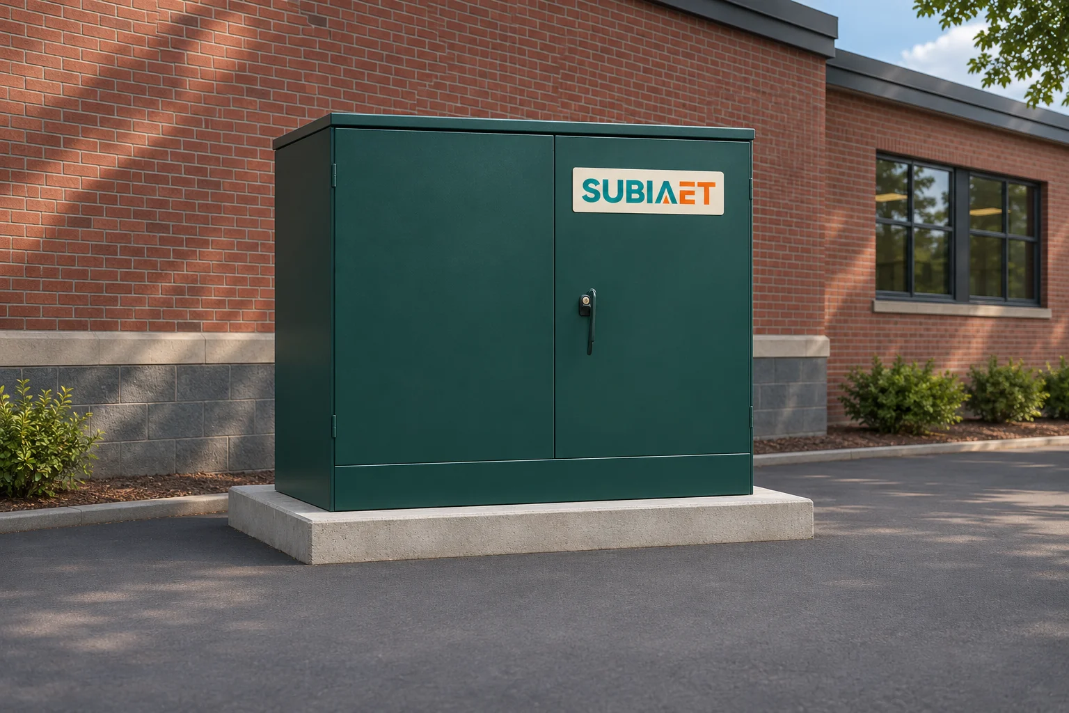
A pad-mounted transformer is a transformer built into a secured cabinet that stands on a ground-level pad, typically made of concrete, with its primary and secondary connections behind secured doors. In a common distribution arrangement, underground cables rise into those connection spaces. The decisive detail is the split between what is above grade and what is below: the cabinet, the transformer and the terminations are above grade, while the cables in this arrangement run buried and rise into the enclosure from underneath. The term describes an installation and enclosure form. It does not fix the phase count, the kVA rating, the winding arrangement or whether the unit is liquid-filled or dry-type, and it should not be read as a performance claim.
The pad is a concrete slab placed at grade, sized to the footprint of the unit and located to suit the cable design, access and site layout. Utility practice in residential areas typically puts these slabs above ground near the customers they serve, and treats the ground around them as space that must stay clear enough for maintenance crews and for service restoration after an outage. That last point is why the pad is a planning object and not a leftover: the slab defines a fixed, findable working position, supports the equipment above bare soil, and provides the level bearing surface required by the enclosure design. Pad elevation, grading and drainage still need to be designed for the site; a slab alone does not prevent standing water.
The cabinet sits on top of that slab. Cabinets vary in height, roof form, door layout and finish, but the function is to house the equipment and control access to the terminations. The specified enclosure design determines its weather protection and access provisions. The doors are the interface the public sees; the terminations behind them are the part that matters electrically.
The cables come from below. Ducts or conduit are buried along the route, and under the cabinet they turn up and enter the enclosed termination area. That below-cabinet entry is the typical geometry for a cable-fed unit; some configurations instead bring the secondary out through a different arrangement, such as a busway connection, which changes the interface the site has to prepare. The practical consequence is that the pad is not just a platform — it is the roof of the cable approach. Whoever sets the slab is also fixing where the ducts land, and a duct bank that arrives under the wrong corner of the slab is a field problem, not a drawing problem.
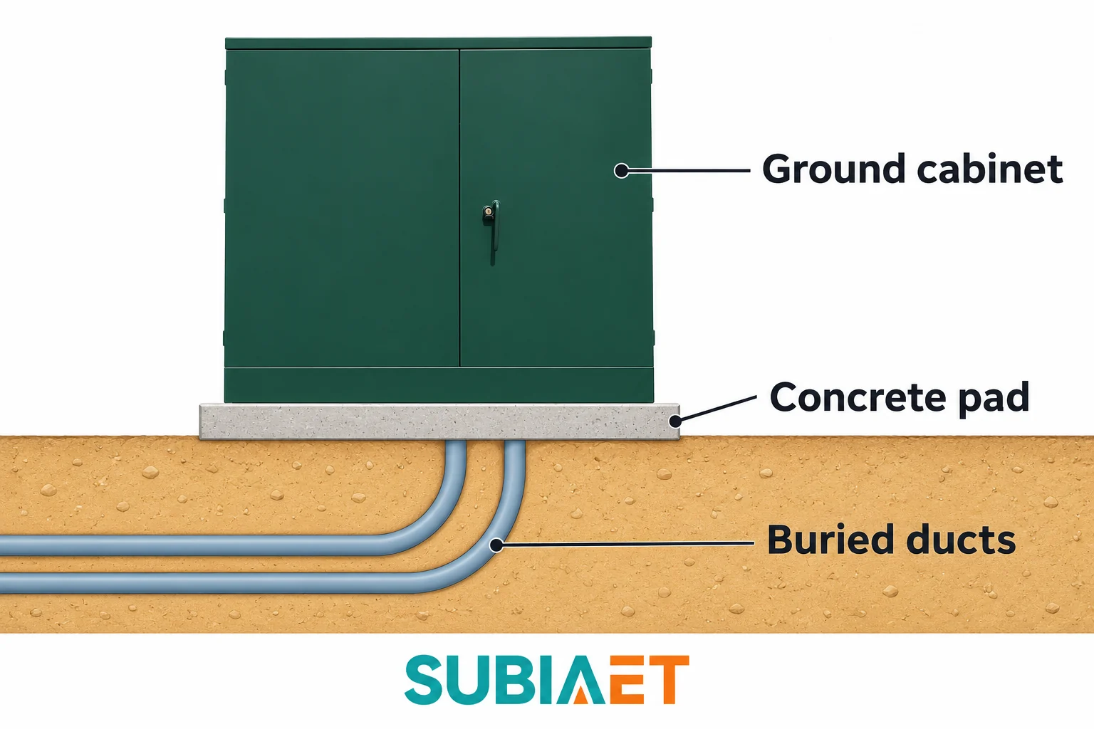
This is the point where two different products get confused. A below-grade vault that houses the transformer, and a submersible unit intended to keep operating when submerged, are separate constructions with their own sealing, enclosure and installation requirements. A pad-mounted cabinet is above grade by definition; it is not flood-rated because its supply happens to be underground. If a site is in a floodplain, in a location where the pad would pond, or in a below-grade chamber, that condition has to be specified and answered with the construction designed for it, not absorbed into a standard pad-mounted unit.
Omaha Public Power District’s guidance provides a utility example of keeping access clear; its local requirements are not a universal clearance schedule.
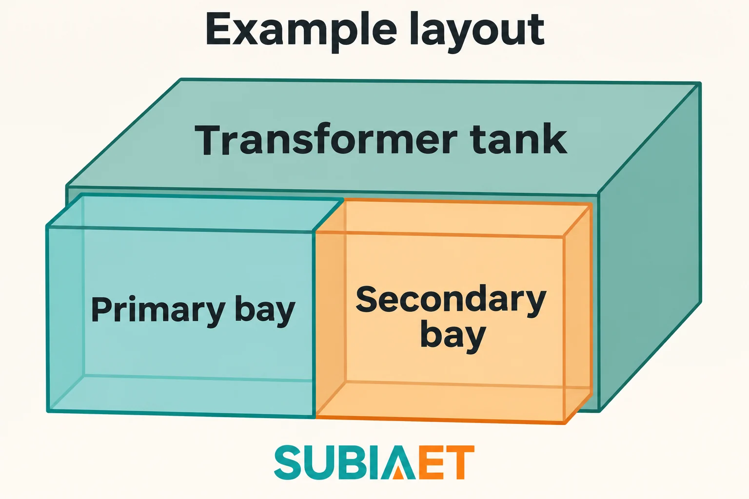
The illustrated enclosure contains three functional groups: the transformer itself, the place where the primary cable terminates, and the place where the secondary cable terminates. The secured doors control access to those groups. Entry and work depend on the equipment and the authorized site procedures.
In the illustrated liquid-filled three-phase example, the cabinet contains the transformer tank at the rear and two termination spaces at the front — one for the primary and one for the secondary — with a barrier drawn between the termination areas. The tank houses the active section: core and coils immersed in insulating liquid, with bushings or leads bringing the winding ends into the termination space. The primary space is where the incoming medium-voltage cable is connected; the secondary space is where the outgoing low-voltage cable that serves the load is connected.
The barrier has a straightforward job. It keeps the medium-voltage terminations, and the cable bends that feed them, in a compartment of their own, and separates those spaces in the cabinet layout. The barrier alone does not establish electrical isolation or permission to work on either side. It also organises cable training: medium-voltage cable needs a controlled bend radius and a firm support point, and a dedicated compartment gives both. Designs with separate door sets may also use different access or locking arrangements for the two sides. None of this is universal. The example shows one arrangement; other products put the compartments in different positions relative to the tank, use a different number of doors, or separate the functions in another way. Treat the illustrated layout as a way to read the object, not as a template for a drawing.
Accessories are where two cabinets that look alike diverge most. Termination, switching and protection options vary: some units include switches and fuses in the primary circuit, others rely on switching or protective equipment elsewhere in the circuit. Connector style, surge protection, gauges, drain and fill provisions, lifting points and the finish system are further items to check in the selected design. Their availability and arrangement depend on that product. A dry-type unit can also be built into a pad-mounted enclosure, in which case the active assembly uses non-liquid insulation rather than an oil-filled tank. Its ventilation or other heat-rejection arrangement and required clearances must match that design. The practical rule is that the cabinet outline tells you the installation form; only the equipment schedule tells you what the unit actually contains.
Eaton’s pad-mounted application guide shows a compartmental design and termination, switching and protection options.
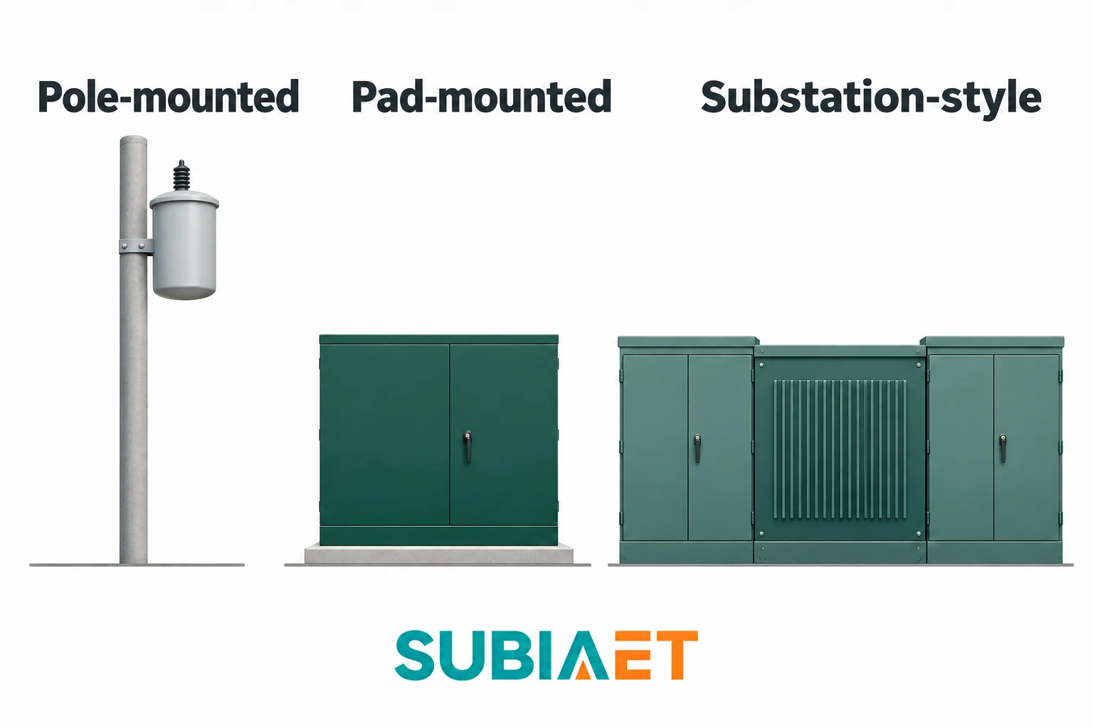
All three forms can serve a distribution voltage-transformation duty when designed for it. What separates them is where the equipment sits, what holds it up, and what has to be built around it.
An overhead pole-mounted transformer is supported on a pole or overhead structure. An overhead primary feeder is a common arrangement; the secondary can connect to overhead or underground circuits. The installation needs the structural support, electrical clearances and service access specified for that design. Where an overhead network already exists, this may avoid building a separate ground-level transformer cabinet, although the complete installation can still require civil and cable work.
A pad-mounted unit trades that structure for a slab, a duct system and a lockable cabinet. Compared with the overhead example, the cable-fed pad arrangement has a lower visual profile and a defined equipment location that can be set into a verge, a parking island or a service yard when the site and utility permit it. The cost is civil work: excavation, ducts, the slab, and a cable route that has to be planned before the concrete is poured.
A close-coupled substation-style unit is a different scope again. There the transformer is mechanically and electrically coupled to switchgear and distributed as a coordinated lineup rather than as a single cabinet, so one common assembly includes primary switching, the transformer and secondary distribution sections in one arrangement. Manufacturer design guides distinguish the pad-mounted enclosure style from the close-coupled unit substation type for exactly this reason: they answer different questions and carry different footprints, interfaces and package boundaries.
| Form | Where it sits | How it is fed | What the site must provide |
|---|---|---|---|
| Pole-mounted example | On a pole or overhead structure | Overhead primary conductors | Specified support, clearances and service access |
| Pad-mounted | In a cabinet on a slab at grade | Buried cable rising under the cabinet | Slab, ducts, cable route, clear access |
| Close-coupled substation example | In a coordinated equipment lineup | Cable or busbar into the lineup | Layout-dependent footprint, civil works and coordinated package boundary |
Two distinctions are worth holding separately from that comparison. First, phase count: single-phase pad-mounted units exist in their own formats, including clamshell designs, and guides describe single-phase pad-mounted equipment alongside three-phase compartment units. Second, ratings and cooling: the pad is not what determines kVA, winding configuration, impedance or cooling class. A single-phase unit and a three-phase unit can both be pad-mounted; a liquid-filled and a dry-type unit can both sit in a pad-mounted enclosure. Deciding “pad-mounted” answers the installation question and leaves the electrical questions open.
Eaton’s transformer fundamentals shows both phase arrangements. Schneider Electric’s distribution guide distinguishes pad-mounted and close-coupled substation enclosure styles and includes a dry-type pad-mounted example.
The recognizable case is a residential development built with underground distribution. Say a developer is laying out a subdivision of detached houses fed from a medium-voltage cable loop, with service pedestals at each lot. The transformers might sit on the verge at the corner of two streets, in a small landscaped island, or at the edge of a parking court, each serving a group of homes through low-voltage cable. The requirements that drive the layout are unglamorous: the layout must accommodate the service access and setbacks required by the utility, preserve applicable sight lines, and consider transformer sound near occupied rooms. The approved access route may involve an easement or other site arrangement rather than a universal rule about driveways or gardens. If the development is phased, the layout also has to allow a unit and its cable ways to be added later without digging up finished landscaping.
A commercial or school site makes the same object look different. Here the load is concentrated: a school building, a retail block or a small industrial tenant may call for a three-phase unit near the building’s service entrance, with the main switchboard nearby. Higher secondary current can require larger or parallel conductors; shortening the route can reduce voltage drop and cable burden. The termination space and yard layout must accommodate the actual cables, pulling work and any planned extension. The arrangement follows the service and site design rather than the building type alone. Because the site has staff and maintenance contractors, the split of responsibility between the utility’s equipment and the facility’s equipment becomes a practical question rather than a paperwork one.
In both cases, only some units include switches and fuses. A unit with a suitably rated primary switching and fuse arrangement can provide specified switching and protection functions locally; a unit without them relies on the equipment assigned those functions elsewhere on the circuit. A load-break switch is not, by itself, a short-circuit interrupting device or proof of an isolating function. That single difference changes the operating procedure, the number of pieces of equipment on site and who is allowed to operate what, so it belongs in the specification rather than in a post-order clarification.
When you approach a supplier, the useful package is specific. It includes the single-line diagram showing what is upstream and downstream, the pad outline with the cable approach direction and the clearances the site can actually hold, the electrical ratings for the transformer itself, the termination arrangement including cable type and size at both voltage levels, the accessory list with switching and protection called out explicitly, and an agreed statement of what the supply covers — cabinet only, or cabinet with cable, pad, ducts, fuses and commissioning support. Published clearance figures are utility-specific; they are a good starting point for a conversation with the local utility and a poor substitute for its written requirement.
SUBIA’s current pad-mounted series page lists ZGS designations at 150 kVA, 500 kVA and 1,000 kVA. Those are the designations published on that page and describe the page’s scope; they are not verified specifications for a particular project until the table, the operating conditions and the configuration are read together for that order. Do not infer a complete station scope from the pad-mounted label. A transformer with integrated switching or fusing and a package with separate MV and LV assemblies can have different boundaries; compare the actual equipment list before treating quotations as equivalent.
For the surrounding context, see the pad-mounted transformer range, the utility secondary distribution application page, the overview of transformer types by function, insulation, phase and installation, and the explanation of what a distribution transformer does in the power system.
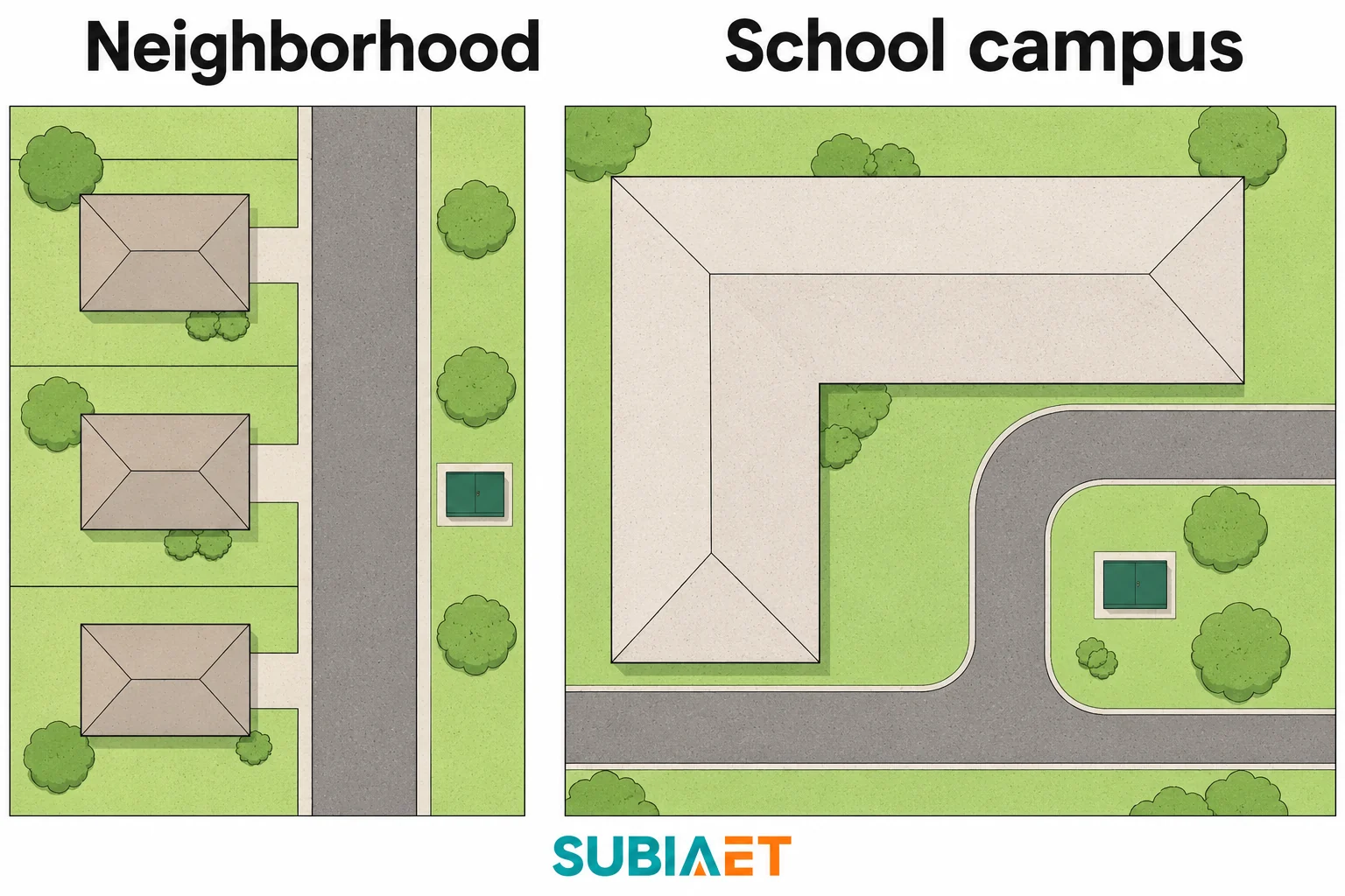
No. The cabinet and transformer sit above grade on the pad. In a typical underground-fed arrangement, the ducts and cables approach below grade and rise into the enclosure. Confirm the actual cable-entry layout on the project drawing.
Yes. Single-phase and three-phase designs both exist. Check the specified phase count and the connection drawing for the unit being considered.
They identify where the two sets of terminations are arranged. The figure shows one three-phase layout. The manufacturer’s drawing identifies the bay positions, doors and any specified separation for a particular unit.
The service agreement and project scope assign those responsibilities. Confirm who supplies each item, who commissions it and who maintains it. The cabinet location alone leaves these responsibilities open.
