Request a Quote
Share the equipment and project requirements. If you need help selecting a model, describe the application.
Have drawings or specifications? Email [email protected] with your project reference.

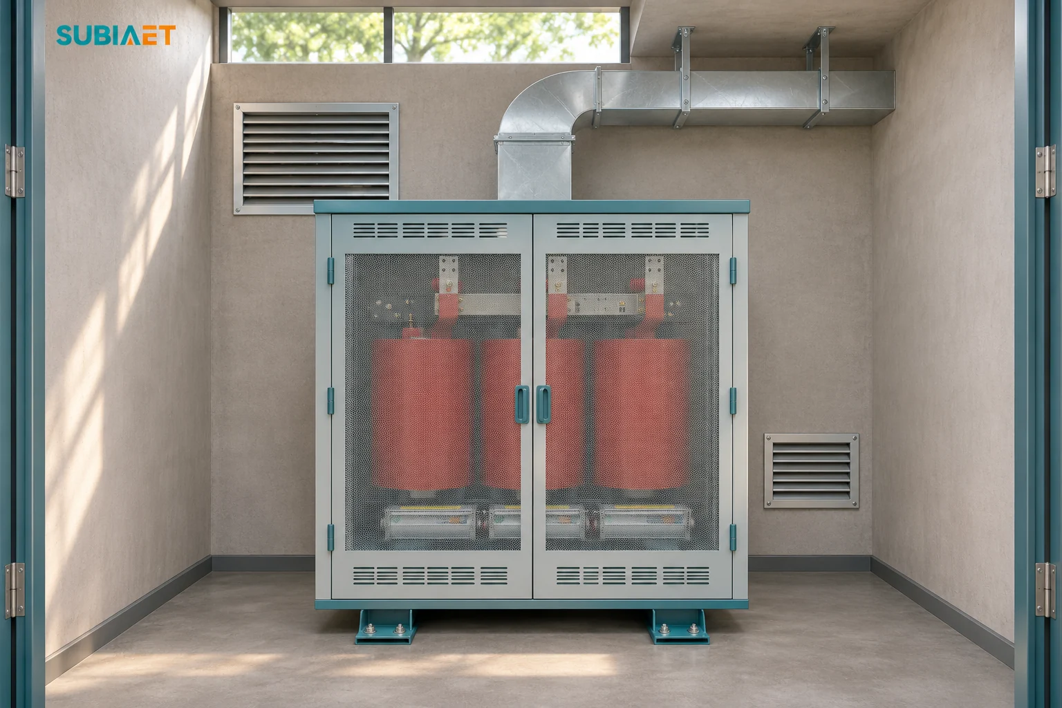
Transformer room ventilation is decided by two questions. The first is thermal. Determine how much sensible heat the room must remove and what effective air volume that implies across the actual inlet-to-exhaust path. The second is moisture. Check whether any surface in the room can fall below the dew point of the air touching it. Light load, shutdown and restart deserve their own checks because the equipment and nearby surfaces can cool.
A room can pass the heat check and still have condensation on vulnerable equipment. It can also look dry and clean during a standby inspection while the equipment inlet exceeds its allowable air temperature in service. Work through the heat inventory, airflow estimate, real pressure path, enclosure and access constraints, moisture check and evidence needed for design and commissioning release.
The heat budget is a property of the transformer, the other equipment in the same air zone, the enclosure or room envelope, and the duty you actually intend to run. Start by defining the air zone, including where air enters, mixes and leaves. Everything that releases heat inside that boundary belongs in the inventory. Include heat transferred in across its boundaries where relevant, and account for heat removed by other paths separately.
A transformer’s losses are two different quantities with two different behaviours.
No-load loss, often called core loss or iron loss, exists from the moment the transformer is energized. It comes mainly from hysteresis and eddy currents in the core. For a first screen it is approximately constant at the same voltage, frequency, tap and waveform, including when the transformer is lightly loaded. Include the relevant no-load loss in loaded and energized standby cases.
Load loss includes the I²R loss in the windings plus additional losses such as eddy and stray losses. At the same winding temperature, the resistive portion rises with the square of current. At half the rated current it is about a quarter of its rated-current value, and at 80% it is about 64%. Confirm the complete load loss with the supplier. For the heat budget, establish the sustained current the transformer will carry through the hottest credible period rather than the sum of downstream nameplate ratings.
Check two details on the loss schedule.
The first is temperature basis. Load loss data is often quoted at a reference winding temperature stated by the manufacturer. Winding resistance rises with temperature, so the resistive portion of a load loss quoted at one reference temperature may differ at another. Other loss components need their applicable correction. Ask for the loss at the modeled duty or the agreed correction, especially for a heavily loaded unit near a thermal limit.
The second is waveform. Loss data is normally quoted for stated test conditions. Harmonic-rich loads, including rectifiers, drives, PV inverters and electronic power supplies, can increase winding eddy losses and stray losses in ways that a rated-frequency figure does not capture. If the transformer serves a harmonic-rich load, ask the supplier what the loss data covers and provide the expected current spectrum and duty for an assessment of that configuration.
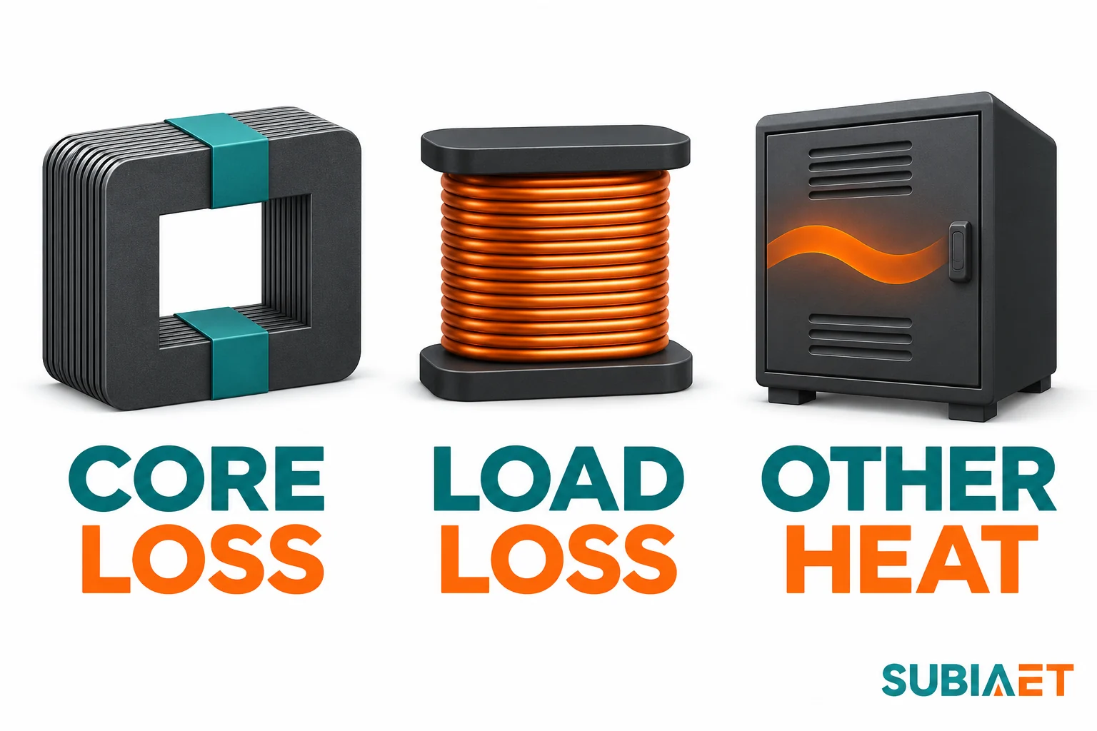
The inventory has three practical groups.
Transformer losses. No-load plus load loss at the credible duty, on a consistent temperature basis, plus any auxiliary loss that ends up as heat in the same air.
Other coincident heat. MV switchgear and its instrument transformers, LV distribution boards, busbar trunking, cable terminations and sealing ends, power factor correction, local lighting, small power, and any battery or UPS equipment sharing the room. Add the losses or other heat actually released into the same zone in the modeled state. This heat can be significant in a lightly loaded substation.
Envelope and solar gain. For an indoor room, consider solar through glazing, heat flow through sun-exposed walls and roof, and heat transfer from adjacent spaces. For an outdoor prefabricated enclosure, direct solar on the enclosure can raise internal temperatures. The IEC 62271-202:2022 public synopsis notes that the edition includes an informative annex addressing solar effects on enclosure temperature. Use project exposure and the relevant assembly evidence.
Three common boundary mistakes change the result.
Use loss in kW for the heat input. Transformer kVA describes apparent electrical capacity. Use the offered loss data for the relevant load and conditions to find heat released. If the only available information is efficiency, first establish the active-power, loading, power-factor and test basis before deriving losses.
Locate where heat is released. A tank, external radiator or outdoor compartment can reject heat to air outside the zone being evaluated. Other heat can still cross back through the enclosure or adjacent construction. A dry-type transformer inside a room without a separate heat rejection path usually releases its losses within the room through convection and radiation. Account for the portion the room airflow must remove.
Separate transformer-mounted forced cooling from room ventilation. A fan bank blowing across cast-resin windings can support an increased rating if the manufacturer has designed and approved the configuration for it. The heat it moves off the winding is still delivered to the same room if it discharges there. The Schneider Electric TRIHAL installation and maintenance instructions separate premises extraction from transformer-mounted forced cooling and direct the user to revisit inlet and outlet sizing for the configuration supplied. Recheck the room heat budget at the approved fan-assisted duty.
The same manual illustrates the room-side method. It uses net lower intake and upper outlet areas, their height difference, and room dissipation derived from the transformer’s no-load and load losses on their stated temperature basis plus other equipment in the premises, with explicit allowance for mesh obstruction. Its empirical method applies to that product and geometry, an annual average room temperature of 20 °C and altitude up to 1,000 m. Obtain the offered equipment’s own room conditions and opening requirements.
With a sensible heat load P in watts, the airflow required to carry it away at a chosen air temperature rise is:
Q = P / (ρ · c_p · ΔT)
With Q in m³/s, ρ in kg/m³, c_p in J/(kg·K) and ΔT in K, the relation gives the general sensible heat balance in the 2017 ASHRAE Handbook—Fundamentals, Chapter 16, Eq. (33). Its near-sea-level shortcut uses density around 1.2 kg/m³ and specific heat around 1,000 J/(kg·K) for a first estimate. Use the site conditions for the actual design.
Two disciplines keep the arithmetic honest.
Keep the units consistent. Using P in W, ρ in kg/m³, c_p in J/(kg·K) and ΔT in K gives Q in m³/s. Multiplying by 3,600 gives m³/h. You can instead use P in kW and c_p in kJ/(kg·K). Mixing kW with a J-based heat capacity, or W with a kJ-based heat capacity, changes the result by a factor of a thousand.
State the density you used. Air density generally falls at higher elevation or temperature, for otherwise comparable conditions. Because the equation is a mass-flow balance written in volume terms, the same heat load and temperature rise require more volume flow at lower density. Use the site air density in the fan and system performance checks as well as the heat calculation.
ΔT is the difference between the air entering the zone and a representative exhaust temperature. For a bulk balance, use an exhaust average that represents the air leaving the zone, rather than the temperature in the plume directly over the transformer. A local hot reading can identify poor air distribution, but it cannot establish the total flow. Use the equation to screen the defined heat removal path:
The same ASHRAE chapter treats latent heat from moisture changes separately. A ventilation path that carries away sensible heat can still leave a moisture problem or introduce humid air.
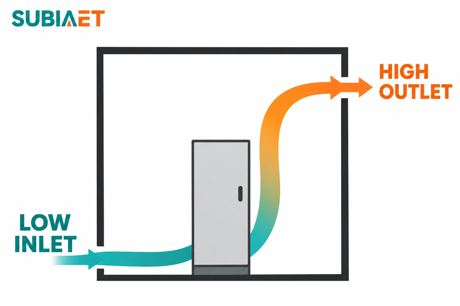
A calculated airflow is a target. What the room receives is installed performance, which depends on the pressure and route through the actual system.
An unassisted room can move air by stack effect and wind. A simple stack pressure estimate is the cold-to-hot air density difference multiplied by gravitational acceleration and the height between openings. That driving pressure can be small compared with the pressure loss through weather louvers, a mesh screen or ducting. Assess the pressure available and the actual resistance at the intended airflow under the design conditions.
Natural ventilation needs sufficient net free area, a useful height difference and a low-resistance path. Wind can help or oppose the flow, depending on the opening exposure and conditions. The Schneider Electric Electrical Installation Guide’s discussion of MV substation ventilation illustrates low and high openings arranged to assist natural convection near the transformer. It also distinguishes the location of those openings relative to switchboards and covers intake baffles, humidity and water entry.
A fan’s published free-air figure is the flow at zero external static pressure. The fan operates where its curve intersects the system curve, which includes the resistance of louvres, filters, duct runs, bends, transitions, silencers and the room’s own internal obstructions. Use the applicable fan and system curves on the same density and pressure basis. Check the fan operating range and controls as resistance changes.
Practical consequences for a transformer room:
The Evoenergy chamber-type substation standard illustrates how one utility distinguishes natural louvres from mechanical ventilation for particular chambers. It relates cooling supply and exhaust to the transformer arrangement, checks duct route and resistance, and addresses design approval, weather protection and filter upkeep. It illustrates low supply and high exhaust with rain protection at the external air intake. Apply the requirements of the utility and authorities for your project.
Ventilation hardware has to fit the enclosure and fire compartment, meet requirements at the property boundary, and remain accessible for maintenance. Each interface can impose constraints that matter alongside the airflow number.
Use approved equipment inlets and clearances. Equipment manufacturers publish minimum clearances and permissible opening locations. Airflow past a winding, dielectric clearance, access and any applicable arc-performance provisions can depend on them. Keep the manufacturer’s inlets and the space in front of compartment doors free of ductwork and other obstructions.
Keep the enclosure evidence tied to its configuration. A prefabricated substation’s ingress protection, mechanical integrity and any declared internal arc performance belong to a specific configuration that was designed and verified. Cutting an additional louvre, enlarging a grille or adding an HVAC penetration changes that configuration. Before any change, have the supplier and responsible designer review the original design and test coverage. Agree further assessment or verification with the relevant authority or testing body where applicable.
Respect the fire strategy. Room fire compartmentation, penetration seals, any required fire dampers in ventilation paths, and separation distances to boundaries and other occupancies can be building and utility requirements that run alongside the electrical design. Coordinate the opening and intended ventilation response with the approved fire design, including the applicable fire and normal states.
Check the actual environment. Outdoor enclosures can face driven rain, snow, dust, sand, insects and vermin, standing water and, near coasts or industry, corrosive atmospheres. Pest screens, rain hoods, louvre blade orientation, sill heights and drainage can affect free area and resistance. Check the actual opening and pressure loss with the selected weather protection fitted. Acoustic limits matter too. Verify noise at the fan’s required operating points, including any night-time conditions.
Keep the access. Filters need changing, fans need replacing, dampers need inspecting and instruments need reading. Check the access route with the approved electrical and service clearances. A filter that is difficult to reach can become a long-term airflow restriction, so establish the service route while the equipment layout is being finalized.
IEC 62271-202:2022, edition 3.0 with the incorporated 2023 corrigendum, addresses AC prefabricated substations above 1 kV and up to and including 52 kV within its stated scope. This includes enclosed, cable-connected high-voltage assemblies for outdoor installation, with a three-parameter assembly rating and revised continuous-current temperature-rise methods described in the publisher’s synopsis. A site-built transformer room inside a building also needs its applicable utility and building requirements. For a prefabricated package, obtain the configuration-specific assembly rating and the thermal evidence that goes with the configuration you are actually buying, including whether a changed transformer, enclosure, ventilation arrangement or installation falls within that evidence.

Condensation depends on moisture and surface temperature. More airflow may help dry a room or bring in air with a higher dew point. Check the operating state and incoming air conditions separately from the sensible heat calculation.
The dew point is the temperature at which air of a given water vapor content and pressure becomes saturated as it cools. If an exposed surface is below the dew point of the air immediately around it, moisture can condense on the surface.
Two things follow, and both are easy to get wrong.
First, the comparison is local. The dew point that matters is the dew point of the air adjacent to that surface, and the surface temperature that matters is that surface’s own temperature. A room whose bulk air is comfortably warm can still have a cold incoming cable gland, a cold tank base, a cold concrete wall or a cold metallic door frame sitting below the local dew point.
Second, raising the air temperature does not remove water vapor. Sensible heating lowers relative humidity and leaves the dew point approximately unchanged at the same moisture content and pressure. Actual air exchange can change the dew point. A heater can keep nearby surfaces warmer, while other surfaces and later shutdown conditions still need a separate check.
A typical sequence starts with equipment running warm. Load drops or the transformer is switched out and the metal cools. If warm, humid outdoor air then enters through the ventilation path, some surfaces can be below that air’s local dew point and condensation can form.
The Schneider Electric BlokSeT technical FAQ on space heaters describes this risk for a low-voltage switchboard. It discusses a cooled, shut-down cubicle, changing day and night temperature and humidity, and keeping the relevant compartment conditions above dew point with a heater assessed for that configuration. Compartment geometry can change the heater’s coverage.
Use anti-condensation heaters only as accepted for the actual equipment and its controls. Assess which surfaces they protect and how they operate during standby. A heater specified for one compartment layout may give different results in a larger or subdivided enclosure. Consider separate air or humidity control where the environment warrants it.
Separate the sources of water so that the controls address how it reaches the equipment.
Ingress is liquid water finding a path in through a louvre, splash at a sill, a failed gasket, a blocked drain, a cable entry or standing water in a plenum. Relevant controls include louvre design, rain protection, sill geometry, seals and a safe drainage path. The Evoenergy example addresses water in a concrete plenum and rain protection at the outside air intake. Coordinate the actual drainage, cable entry and containment design with the civil works and applicable requirements.
Condensation is vapor turning to liquid on a surface that is too cold. Manage the dew-point relationship by limiting moisture entry, using ventilation or dehumidification as appropriate, or keeping the vulnerable surfaces above the local dew point. Arrange safe collection or drainage where the design allows for condensate. Drainage cannot protect a terminal or insulation surface on which condensation forms directly.
Set the moisture and temperature acceptance basis using the site’s actual humidity and temperature history, the equipment’s approved conditions and the vulnerable surfaces. Record observations in the relevant operating states.
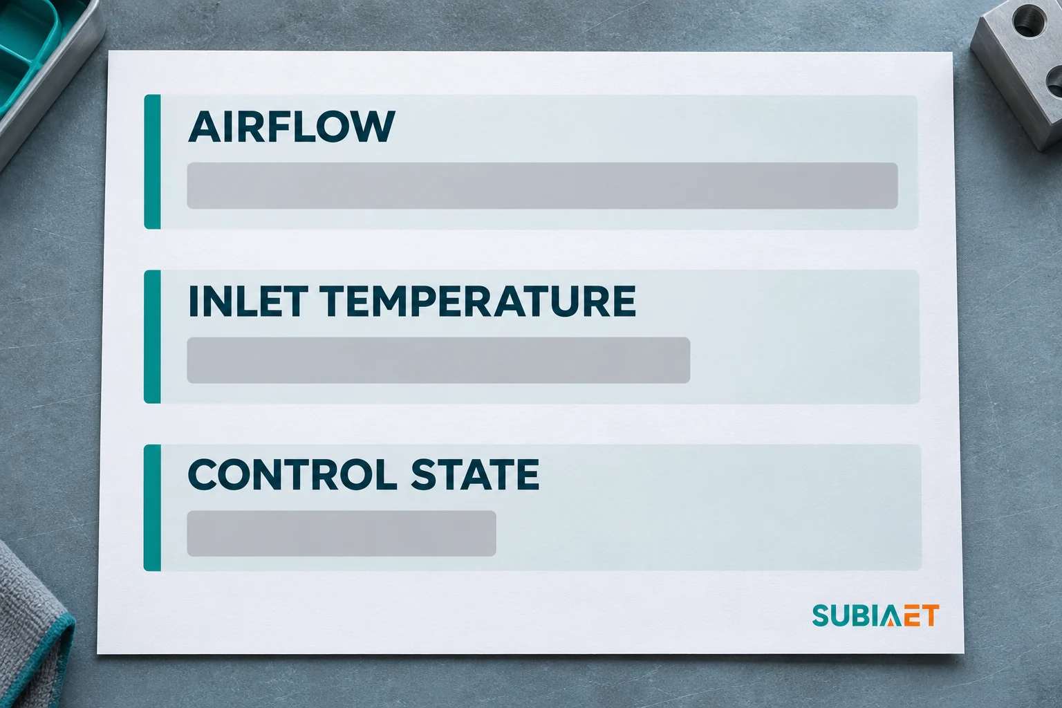
Design calculations and factory evidence support the proposed configuration. Commissioning checks what the installed system delivers. The U.S. Department of Energy Ventilation Assessment and Action Guide illustrates this distinction in its commercial-building testing and balancing guidance. It discusses verifying system and sensor function, possible adjustment of fan static pressure, and measuring actual supply flow. Define the electrical room’s thermal and moisture acceptance conditions separately.
Define the credible operating modes in advance and agree the acceptance conditions for each one.
Verify the room in its intended operating state with doors closed, panels fitted, filters in place and realistic electrical duty. Under the site’s safety rules and the approved commissioning plan, have qualified personnel record:
These records belong together. Compare the measured flow with the design basis using the same equipment duty, air temperatures, fan and pressure state. If the test load or weather is milder than the design case, record what the test demonstrates and agree how remaining conditions will be checked. Keep the measurement locations and acceptance criteria with the results.
Fictional steady sensible-heat screen and standby moisture check. The inputs and acceptance conditions are assumptions for one room.
One room with a ventilated dry-type transformer has a 30.0 °C supply-air case and a project-assumed representative mixed exhaust target of no more than 40.0 °C. The 10.0 K difference is the design air-stream rise for this one screening case. Use ρ = 1.18 kg/m³ and cp = 1.005 kJ/(kg·K). The condensation observation belongs to a separate standby state.
| Item | Basis or arithmetic | Result | What it means |
|---|---|---|---|
| Room sensible heat | 2.0 kW no-load loss + 9.0 kW actual-duty load loss + 3.0 kW other coincident room heat | 14.0 kW | Use heat released within the defined room at the modeled duty. |
| Screening airflow | 14.0 ÷ (1.18 × 1.005 × 10.0) | ≈ 1.18 m³/s, about 4,250 m³/h | Required effective air exchange by the ideal sensible balance. |
| Installed airflow | Measured effective flow in this illustrative closed-door state | 0.90 m³/s | Falls short of the calculated screening flow. |
| Resulting ideal air rise | 14.0 ÷ (1.18 × 1.005 × 0.90) | ≈ 13.1 K; 30.0 + 13.1 ≈ 43.1 °C | Exceeds the stipulated exhaust target. Verify actual equipment inlet temperatures and the pressure/flow path separately. |
| Separate standby moisture observation | Air dew point 18.0 °C; exposed metal surface 16.0 °C | Surface is 2.0 K below dew point | Condensation is possible at that surface. Verify condition and specified moisture controls. |
| Release decision | Room heat removal and standby moisture remain separate | Both require closeout | Review effective airflow and operating assumptions, moisture control and final verification before accepting the room. |
Three points deserve emphasis.
The 40.0 °C figure is the stipulated acceptance condition for this fictional mixed-exhaust check. Apply the offered equipment’s inlet limits and assembly conditions separately.
The 43.1 °C result is an indicative mixed outlet temperature from the steady sensible balance. It assumes the modeled 14.0 kW is removed by the effective 0.90 m³/s and uses a representative exhaust temperature. The room can still contain hotter and cooler paths. Air can bypass the equipment or recirculate near an inlet, even when the measured mixed exhaust is acceptable. Verify the real equipment inlet temperatures and the pressure and flow path separately.
The moisture row belongs to a separate operating state. A surface 2.0 K below the local dew point can collect moisture, even if the airflow passes its heat check. In the model, 13.1 K is the ideal air-temperature rise and 14.0 kW is the sensible heat load. Close the airflow issue and verify standby moisture controls separately before accepting the room.
Close gaps in the equipment and ventilation data before design release. Agree what each party will provide and what will be confirmed at handover.
From the equipment supplier:
From the ventilation design:
From verification and handover:
Responsibility split. The equipment vendor provides the thermal data, permissible conditions and the basis for accepted enclosure openings and changes. The responsible design team coordinates fire protection, drainage and containment with the utility and authorities where applicable. The ventilation designer provides the flow, pressure budget, route, fan selection and control sequence. The owner and commissioning team agree the verification and handover records. The owner assigns filter, drain and fan maintenance and alarm response after handover.
If the room is part of a packaged substation rather than a site-built building, the starting point is the prefabricated substation family and the specific configuration being quoted, and the dry-type transformer page for the equipment that sets the loss figures. Loss data and its operating-cost implications are compared in the transformer loss and total-cost-of-ownership article. Where the transformer relies on forced cooling, the fan dependency is worth understanding before the room heat budget is fixed — see ONAN, ONAF, AN and AF cooling ratings. The assembled-package evidence trail, as distinct from individual equipment tests, is covered in substation FAT versus transformer tests. And because inlet and outlet positions, drainage and cable entries are frozen in civil works, the foundation and cable-entry interfaces should be reviewed at the same time as the airflow path.
Start with the credible sensible heat in kW and the permitted air temperature rise, using Q = P / (ρ · c_p · ΔT). Two rooms with the same transformer kVA can need different flows because of loading, other equipment and solar gain in the same zone. Define the air-side temperature budget, check the actual equipment inlet limits and verify what the installed path delivers.
A larger fan can improve airflow if it reaches the required operating point with the actual makeup-air path and system resistance. An inlet louvre, filter, duct or internal restriction can limit the gain. A stronger exhaust can also change room pressure and draw air through unintended paths, or discharge hot air near its own intake. Review the inlet, exhaust, recirculation and pressure basis before comparing fan selections.
Condensation can occur when a surface falls below the dew point of the air touching it. During operation, some equipment surfaces remain warm while other cold locations can still be vulnerable. After shutdown or during light load, previously warm metal can cool. If humid air then reaches it, the local dew point can be higher than the surface temperature. Assess site moisture entry and the approved heating, humidity control, drainage and inspection provisions for that standby condition.
Obtain a formal configuration review before any change. The approved design and evidence cover the enclosure in a stated configuration, including the relevant ingress protection, mechanical strength, thermal behavior and any declared internal arc performance. Ask the supplier and responsible designer whether altered openings are within the applicable evidence and which approvals or verification are needed. Specifying the openings, weather protection and ventilation at quotation stage lets them be reviewed as part of the offered assembly.
The equation screens the effective air volume needed to remove a stated sensible heat load across an assumed inlet-to-exhaust temperature difference at steady conditions. Actual airflow past a winding, local equipment inlet temperatures, winding hot spots, restrictions and transient behavior require separate checks. Use the relevant equipment or assembly thermal evidence and verify installed flow and temperature at the agreed locations. Check moisture separately during the applicable standby conditions.
