Request a Quote
Share the equipment and project requirements. If you need help selecting a model, describe the application.
Have drawings or specifications? Email [email protected] with your project reference.

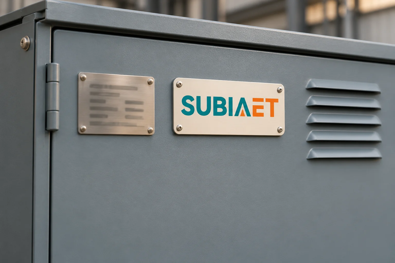
A transformer nameplate is a compact engineering record. It encodes the rated capacity, voltage relationships, winding configuration and declared impedance of a specific unit. The supporting records establish whether a displayed value is nominal, guaranteed or the reported test value. Reading it correctly is the first step in preparing a replacement specification or an RFQ, because every field on the plate has a precise meaning that is different from what meters read in service or what drawings describe about physical interfaces. This article walks through each major field group using a clearly marked teaching example, then assembles those readings into a copy-and-verify checklist.
Before interpreting any value, establish what you actually have. The nameplate is physically attached to the transformer enclosure, typically engraved or stamped on a metal plate mounted on the tank wall or the enclosure panel. Where the plate is accessible under the site’s conditions, start by photographing it under good lighting and recording every visible field into a table or form. Keep two separate columns: confirmed legible values and illegible or missing values. Do not guess at worn characters. A wrong digit in a voltage rating or serial number can invalidate the whole replacement process.
The fields to copy in the first pass are:
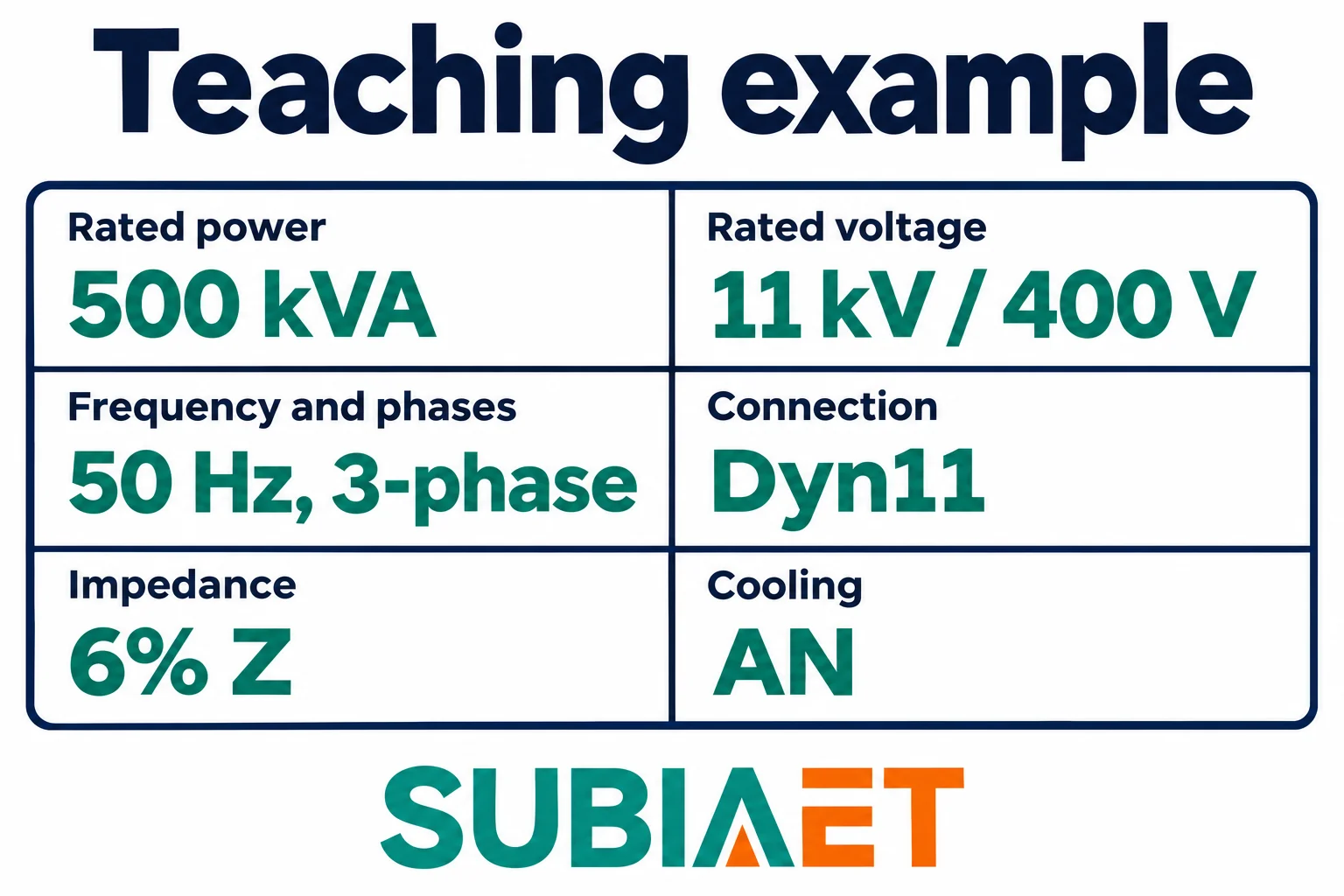
The teaching example used throughout this article is a dry-type unit with the following nameplate data. The values define the teaching example rather than a particular supplied model:
| Field | Illustrative value |
|---|---|
| Type | Dry-type, cast resin |
| Rated kVA | 500 kVA |
| Cooling | AN |
| HV rated voltage | 11 kV (line-to-line) |
| LV rated voltage | 400 V (line-to-line) |
| Phases | 3 |
| Frequency | 50 Hz |
| Vector group | Dyn11 |
| Percent impedance | 6% |
| HV taps | ±2 × 2.5% |
Two distinctions matter immediately. First, the 500 kVA rating states apparent-power capacity under the specified rating conditions, including cooling; it is not the same as the measured demand your existing load draws. A measured demand of 420 kVA is numerically below 500 kVA, but that single comparison does not establish suitability or replacement capacity. The load history, per-phase loading, waveform, growth, starting duty and site cooling conditions still need review. Second, the cooling designation AN indicates natural-air cooling. The kVA rating is inseparable from that cooling condition. Some dry-type designs have a separate forced-air rating. Record that rating only if the manufacturer actually specifies it with the required fans, controls and operating conditions; adding fans alone does not establish extra capacity. Voltage, kVA and thermal rating describe different aspects of the same unit; confirming kVA requires knowing the stated operating conditions.
Eaton’s fundamentals explains kVA and temperature rise, and Schneider Electric’s dry-type document shows an AN rating for its example series.
The two rated voltages identify the intended winding voltage relationship at the specified frequency and tap basis. They are not a guarantee of the exact terminal voltage at every load: supply conditions and internal voltage drop also matter. In the teaching example, 11 kV and 400 V are both line-to-line values on a three-phase unit. For the example’s balanced star-connected LV winding with neutral brought out, 400 V ÷ √3 ≈ 231 V gives the phase-to-neutral voltage. The stated 400 V rating is line-to-line; a neutral or that relationship cannot be assumed for every winding connection. Copy both voltages as printed without converting them, then note the measurement basis separately.
Frequency and phase count are separate fields to copy. Frequency affects the volts-per-hertz relationship, magnetic flux and impedance behaviour. A 50 Hz marking is therefore a separate specification item from 500 kVA. If the proposed supply frequency differs, obtain the manufacturer’s rating or suitability confirmation for that voltage and frequency; matching kVA and voltage alone does not establish the permitted duty.
The tap range printed as ±2 × 2.5% means two steps on each side of the nominal rated voltage, each step being 2.5% of nominal. Applied to the 11 kV nominal HV winding in the teaching example, that produces five discrete rated tap positions:
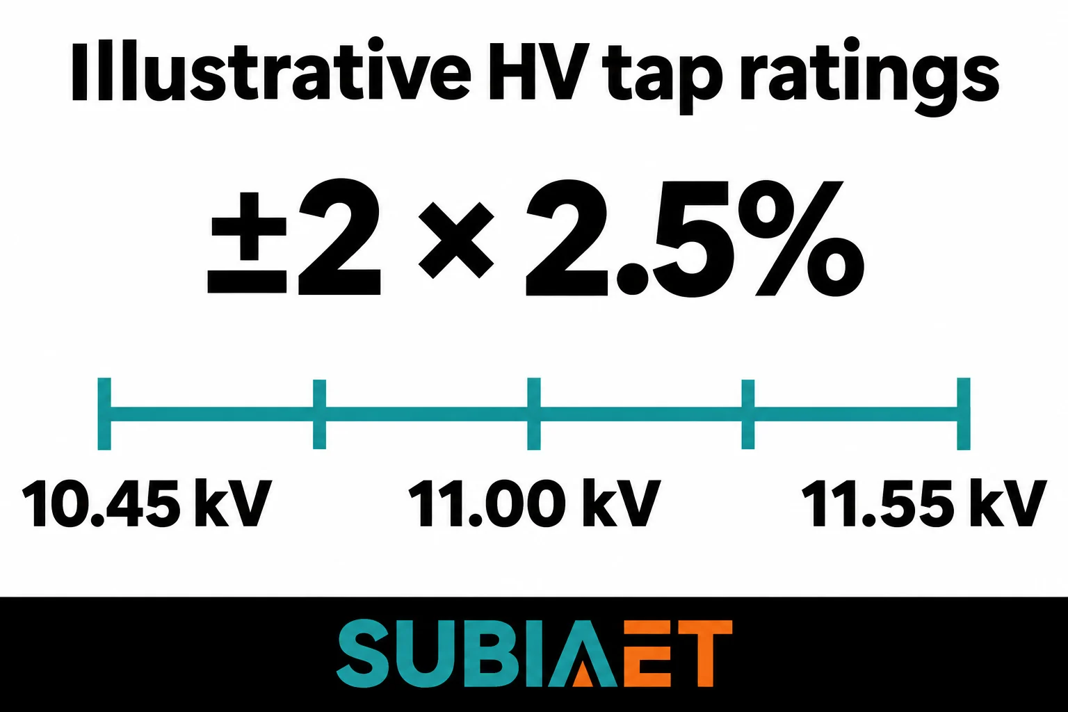
| Illustrative tap level | HV rated voltage | Relationship to nominal |
|---|---|---|
| Highest | 11.550 kV | +2 × 2.5% |
| Above nominal | 11.275 kV | +1 × 2.5% |
| Nominal | 11.000 kV | Nominal |
| Below nominal | 10.725 kV | −1 × 2.5% |
| Lowest | 10.450 kV | −2 × 2.5% |
Each illustrated tap level defines a rated voltage ratio for the HV winding. Actual position identifiers must come from the unit’s own schedule. At the 11.55 kV tap rating, more HV turns are in circuit; applying that rated HV gives approximately 400 V in the no-load ratio model. At the 10.45 kV tap rating, fewer HV turns are in circuit and the corresponding rated supply again gives approximately 400 V. Actual loaded voltage also depends on supply and load conditions. Taps change the effective turns ratio, allowing the transformer to compensate for supply voltage that sits above or below nominal.
Schneider Electric explains the voltage-ratio effect of taps for its low-voltage units.
The critical distinction is between the printed range and the installed position. The nameplate tells you which tap positions exist. It does not tell you which position the transformer is currently set to, and it cannot tell you what the actual supply voltage at this site is. To know the installed tap position, you need the commissioning record or operating log. To know whether that position is still appropriate, you need a current measurement of the actual supply voltage. For a replacement or RFQ, you should copy the full tap range from the plate and then verify the installed position from site records and the outline or terminal drawing — not from the nameplate alone.
Tap range does not identify the permitted mode of operation. A de-energized tap changer requires the equipment to be isolated and de-energized under the applicable procedure; an on-load tap changer is a different mechanism designed for its specified energized switching duty. Read the actual device designation and operating documentation. The nameplate gives the available ratios, not an instruction to change taps.
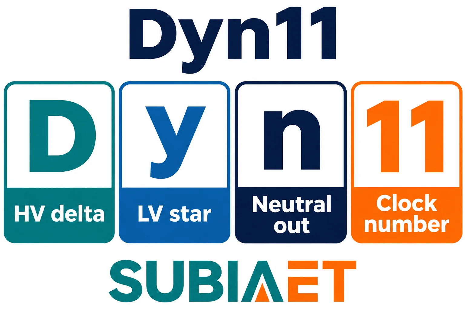
The vector group code Dyn11 is a compact four-element label that describes the winding arrangement, the neutral terminal and the phase displacement between HV and LV voltages. Each element has a specific meaning and the case of the letters is intentional:
| Element | Value | Meaning |
|---|---|---|
| HV winding | D | Delta connection (uppercase = HV winding) |
| LV winding | y | Star connection (lowercase = LV winding) |
| Neutral | n | LV neutral terminal brought out |
| Clock number | 11 | With HV at 12, LV is at 11: a 30° lead in the usual clock convention |
The uppercase D tells you the HV winding is connected in delta. The lowercase y tells you the LV winding is connected in star. The n tells you the LV star point is brought out to a neutral terminal; the installation drawing establishes how that terminal is used. The number 11 represents phase displacement using the usual clock convention: with the HV reference phasor at twelve o’clock, the LV reference points to eleven o’clock, a 30° lead. That reference does not imply that a delta HV winding has a physical neutral terminal.
The connection code gives you the winding topology and the phase angle relationship. What it does not establish on its own is the physical terminal sequence at the HV and LV terminals, the actual grounding arrangement at the installation site, or whether this unit can be operated in parallel with another transformer. Parallel operation requires a compatible phase relationship, voltage ratios and impedance characteristics, together with the intended load sharing and protection. Confirming compatibility also requires the actual terminal diagrams and site earthing arrangement. Those records complement the nameplate; a code alone does not approve paralleling.
ABB’s distribution handbook explains the letter case, neutral notation and clock convention.
Percent impedance is defined using a short-circuit test basis; the nameplate or specification may state a declared value that must be compared with the matching test result. During the short-circuit test at the factory, one winding is short-circuited and voltage is applied to the other winding. The applied voltage is increased from zero until the circulating current reaches the rated value for that winding. The percent impedance is the ratio of that applied voltage to the full rated voltage of the energised winding, expressed as a percentage. In the teaching example, 6% means that 6% of the applicable rated voltage is required to produce rated current on the defined short-circuit test basis; no actual test record is being claimed for the sample plate.
Read 6% Z with the stated frequency, reference temperature, rating base, tap and winding pair. It is not a guarantee that there will be a 6% running voltage drop under load. The actual voltage regulation under real load conditions depends on the load power factor and the separate resistive and reactive components of the impedance, which must be obtained from suitable manufacturer or test data when the study needs them. The 6% figure alone does not establish actual available fault current. A simplified transformer-only estimate assumes a sufficiently stiff upstream source; a real system calculation must assess that assumption. A system-level fault current calculation depends on the transformer impedance, the source impedance from the network behind the HV terminals, and the cable impedances in circuit.
If you are using the percent impedance figure for a protection study or parallel-operation check, you need to match the value to the specific serial number and the reference conditions (temperature and frequency) under which it was measured. Check those details in the matching report and specification, including any correction to a reference temperature. Do not assume every nameplate value is rounded or every report uses the same base, tap or reference condition.
Eaton’s distribution guide explains the roles of transformer and source impedance in a fault study.
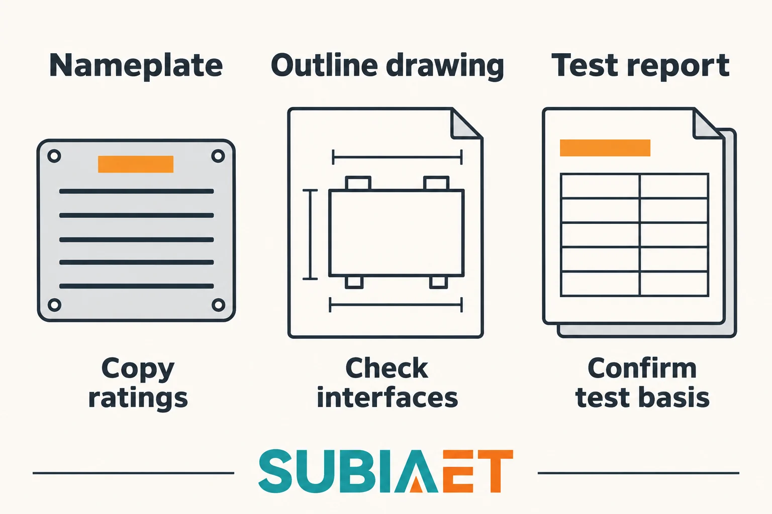
A nameplate reading is a starting point, not a complete specification. The table below shows which fields can be copied directly from the plate and which require a separate document or site check before treating two transformers as interchangeable.
| Field | Copy from plate | Verify separately |
|---|---|---|
| Rated kVA and cooling class | Copy exactly (e.g. 500 kVA AN) | Confirm that the site cooling condition (ambient temperature, ventilation clearances) supports the rated cooling class of the replacement unit |
| HV rated voltage / LV rated voltage | Copy both voltages as printed with line-to-line designation | Confirm actual supply voltage level and whether the rated voltage matches utility nominal or requires a tap offset |
| Frequency and phases | Copy (e.g. 50 Hz, 3-phase) | Confirm site system frequency |
| HV tap range | Copy the full range (e.g. ±2 × 2.5%) | Obtain the installed tap position from commissioning or operating records; verify against outline/terminal drawing |
| Vector group | Copy the full code preserving case (e.g. Dyn11) | Confirm LV terminal sequence, actual neutral connection and earthing arrangement from connection drawing; check parallel compatibility with any adjacent transformer |
| Percent impedance | Copy the nameplate value (e.g. 6%) | Obtain the matching factory test report identified by serial number; verify test reference temperature and frequency; use measured value for protection and parallel studies |
| Enclosure type / IP / dimensions | Copy any visible classification | Obtain outline drawing for external dimensions, weight, cable entry positions and anchor pattern; confirm fit to switchroom or pad |
| Manufacturer / model / serial | Copy all three if legible | Obtain original test report and type drawings using serial number; flag illegible serial for manufacturer trace |
The practical handoff for a replacement or RFQ uses three documents alongside the nameplate reading: the outline and general arrangement drawing (which gives physical dimensions, weight and cable entry positions, with required clearances in the applicable drawings or installation instructions), the terminal or connection diagram (which shows the physical terminal arrangement, labelling convention and neutral connection), and the factory test report identified by serial number (which gives the tests actually performed, their results and basis; temperature-rise evidence may be a separate report rather than part of every routine record). These three documents, combined with confirmation of the actual supply voltage and the installed tap position, complete the picture that the nameplate alone cannot provide.
If a proposed replacement departs from any nameplate field — different kVA, cooling class, impedance tolerance, vector group or tap range — that departure needs an engineering assessment before the units are treated as interchangeable. A matching nameplate is evidence of similar design intent; it is not by itself confirmation that the replacement will perform identically in the specific site and system context.
Schneider Electric’s installation guide shows how drawings and site specifications complement the plate.
For related background on transformer types and sizing considerations, see the transformer product range, the dry-type transformer series, the oil-immersed transformer series, the transformer sizing article for factory expansion projects, and the explanation of why transformers are rated in kVA rather than kW.
Record them as unknown. Use the visible model, serial or site equipment tag to look for the corresponding manufacturer records. Confirm that the documents identify the same unit before carrying a rating into the RFQ.
No. It is based on the short-circuit test conditions. In service, load current, power factor and the transformer’s resistance and reactance affect the voltage change. Check the relevant data when the project needs a voltage-drop estimate.
The plate can show the available tap ratings. Use the unit’s current configuration or operating records to confirm the setting in use.
No. Also verify phase, frequency, connections, impedance, tap range, cooling and physical fit. Compare the proposed equipment with the actual system drawings and site requirements before accepting the substitution.
