Request a Quote
Share the equipment and project requirements. If you need help selecting a model, describe the application.
Have drawings or specifications? Email [email protected] with your project reference.

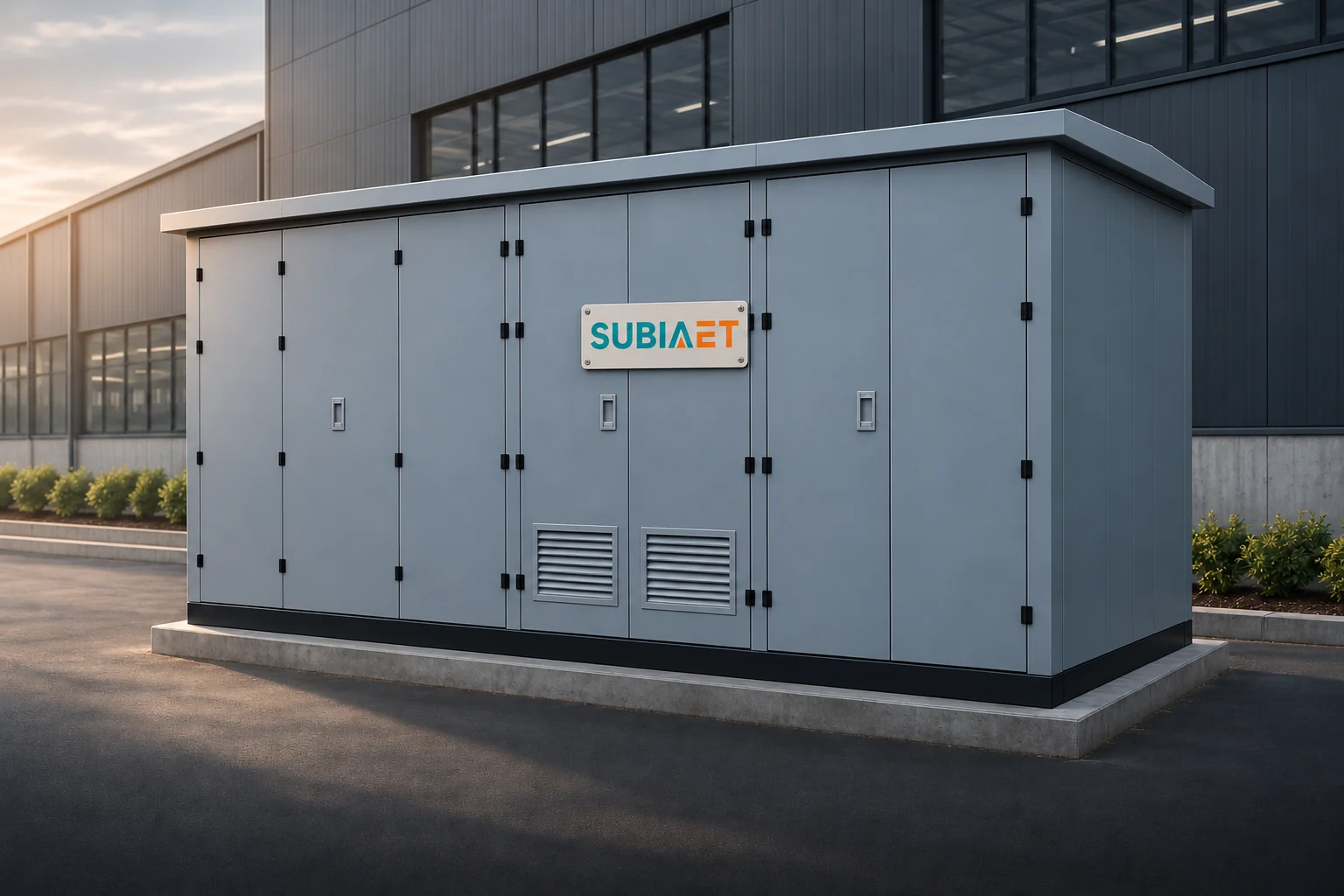
A prefabricated substation is a coordinated equipment package assembled and integrated before it reaches the site. In the step-down example used here, an enclosure groups switching and protection equipment, a transformer, and a low-voltage distribution switchboard. Other prefabricated configurations contain different equipment sets or arrive in transport sections. The transformer is the voltage-changing core of the arrangement, but it is only one of several functions the package coordinates. Understanding what else the enclosure brings together, how power moves through the assembly, and where site work begins is the starting point for anyone specifying, procuring, or installing one of these units.
The IEC 62271-202 scope discussed here addresses enclosed, cable-connected AC prefabricated substations for outdoor installation. It covers substations of this type and distinguishes two broad categories: transformer prefabricated substations, which include a transformer and may include switching and distribution equipment, and switchgear prefabricated substations, which center on the switching and protection function. The IEC 62271-202:2022 scope preview also describes designs that include only part of the full equipment set, so the three-function arrangement described below is one common configuration, not the only possible one.
That three-function configuration groups MV switchgear, a power transformer, and an LV switchboard within a single enclosure. Each has a distinct role. The MV switchgear connects the unit to the incoming medium-voltage supply, provides the specified switching and isolation functions through appropriately rated devices, and—depending on the project specification—incorporates protection for the transformer primary. The transformer steps the medium voltage down to a usable low voltage, providing the voltage needed by the downstream loads. The LV switchboard receives the transformer secondary output and distributes it through outgoing feeder circuits to the building, facility, or network it supplies. The enclosure holds these three functions in prepared, internally interconnected form; this can reduce the equipment assembly required at site. The remaining connections, civil work, inspections and commissioning depend on the package and project scope.
Factory integration can range from a fully wired and tested assembly shipped as one unit to a structure where compartments are prepared and partially interconnected, with some internal connections completed on site. The degree of integration depends on the product design, transport constraints, and project specification.
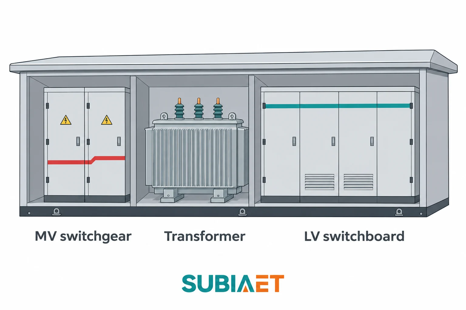
Eaton’s unit substation guide illustrates the close-coupled concept. The term “unit substation” appears in markets influenced by North American practice, particularly under ANSI and NEMA traditions, to describe a close-coupled assembly grouping primary distribution equipment, a power transformer, and secondary distribution equipment. This is a broadly equivalent concept in function, but it reflects a different design tradition and standard context than IEC 62271-202. The two terms are not interchangeable for compliance purposes, and the specific ratings, construction requirements, and test obligations differ between the frameworks.
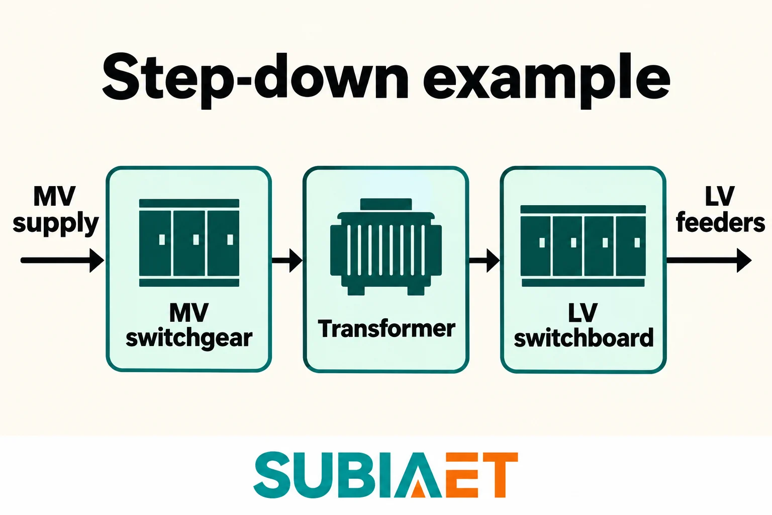
In a typical MV/LV distribution application, power enters the substation from the utility or site MV network through the incoming cable connection. The first point of control inside the enclosure is the MV switchgear. The selected MV devices provide the specified switching, protection and isolation functions. Which device performs each function matters: an open indication or the presence of a switch alone does not establish a safe condition for maintenance.
The choice of protection arrangement at the MV side depends on project requirements and network characteristics. A common arrangement pairs a load-break switch with suitably rated fuses that protect the transformer primary against overcurrents. The load-break switch handles its rated load-switching duty; an isolating function must also be specified where required. In the coordinated switch-fuse combination, the fuses provide the assigned short-circuit interruption duty; a load-break switch alone is not a short-circuit interrupting device and should not be described as one. Where the application requires more flexible or adjustable protection, a circuit breaker with a protection relay replaces or supplements the fuse arrangement, allowing settings to be coordinated with upstream and downstream devices.
Schneider Electric’s protection guide gives examples of these protection arrangements.
From the MV switchgear, the supply reaches the transformer. The transformer windings reduce the voltage to the specified LV level—commonly 400 V or 415 V in systems following IEC practice, though the actual voltage depends on the network and load requirements. Transformer losses contribute heat inside the package, alongside losses in connections and switching equipment. Ventilation or other enclosure heat-rejection provisions must account for the installed equipment and operating conditions.
The transformer secondary output connects to the LV switchboard. The switchboard receives the full secondary current and distributes it through outgoing feeder circuits. Each feeder typically includes a circuit breaker or fuse-switch combination that provides overcurrent protection and isolation for its branch. Some projects add metering at the LV side, either for utility billing or internal sub-metering; the position of metering in the arrangement, and whether it falls inside the prefabricated package or at a separate point, varies with the utility requirement and project scope. Calling out a fixed metering position as universal would be misleading.
Schneider Electric’s substation example shows incoming supply and distribution functions.
The LV feeders leave the enclosure through cable entries to supply downstream loads—motor control centers, distribution boards, individual large loads, or further distribution points.
It is worth noting that the enclosed substation package is not inherently a step-down device. Some applications require the opposite direction: a solar site can receive low-voltage AC from its inverters and step that AC up to medium voltage for a collection network or grid connection. A purpose-designed step-up package addresses this by configuring the transformer and associated equipment for LV-to-MV transformation. The components are conceptually similar to a step-down unit, but the direction of normal power flow, the protection coordination, and in some cases the transformer winding arrangement are configured for the export application. The SUBIA PV step-up substation category provides the product-family context for that renewable generation duty.
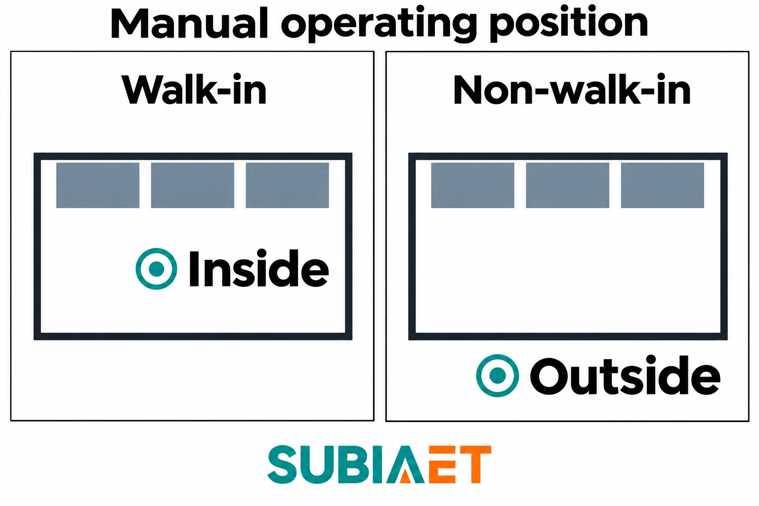
The IEC 62271-202 public abstract describes two classes of prefabricated substation by the position from which an authorized operator carries out normal operations. These are the walk-in type and the non-walk-in type, and the distinction is about where the operator stands during normal operation—not about how many doors the enclosure has or how maintenance is performed.
In a walk-in substation, the enclosure is large enough that the operator enters the interior and operates the equipment from within a defined aisle or operating space. Normal switching and control actions are performed from inside. For example, switchgear panels can face an internal operating aisle. The manufacturer’s layout identifies the operating space and the equipment faces; the category alone does not prescribe the size or panel arrangement.
In a non-walk-in substation, the operator performs normal operations from outside the enclosure. The relevant control and operating elements—such as handles, switches and indication windows—are arranged for operation from outside, as defined by the particular equipment documentation. No internal aisle for that normal operating position is required, which can reduce the space devoted to operation; the actual footprint still depends on the equipment and layout. One example of a non-walk-in enclosure divides its interior into separate compartments for the MV switchgear, transformer, and LV switchboard, with all equipment interconnected internally and accessed from the outer faces.
This distinction should not be confused with questions about maintenance entry, which may require different permissions, procedures, and conditions regardless of whether the unit is classified as walk-in or non-walk-in. It also should not be equated with structural safety properties; the classification reflects the normal operation position as defined within the standard’s scope, not the safety provisions that apply during other activities. Similarly, door count is a consequence of access design, not the basis of the classification.
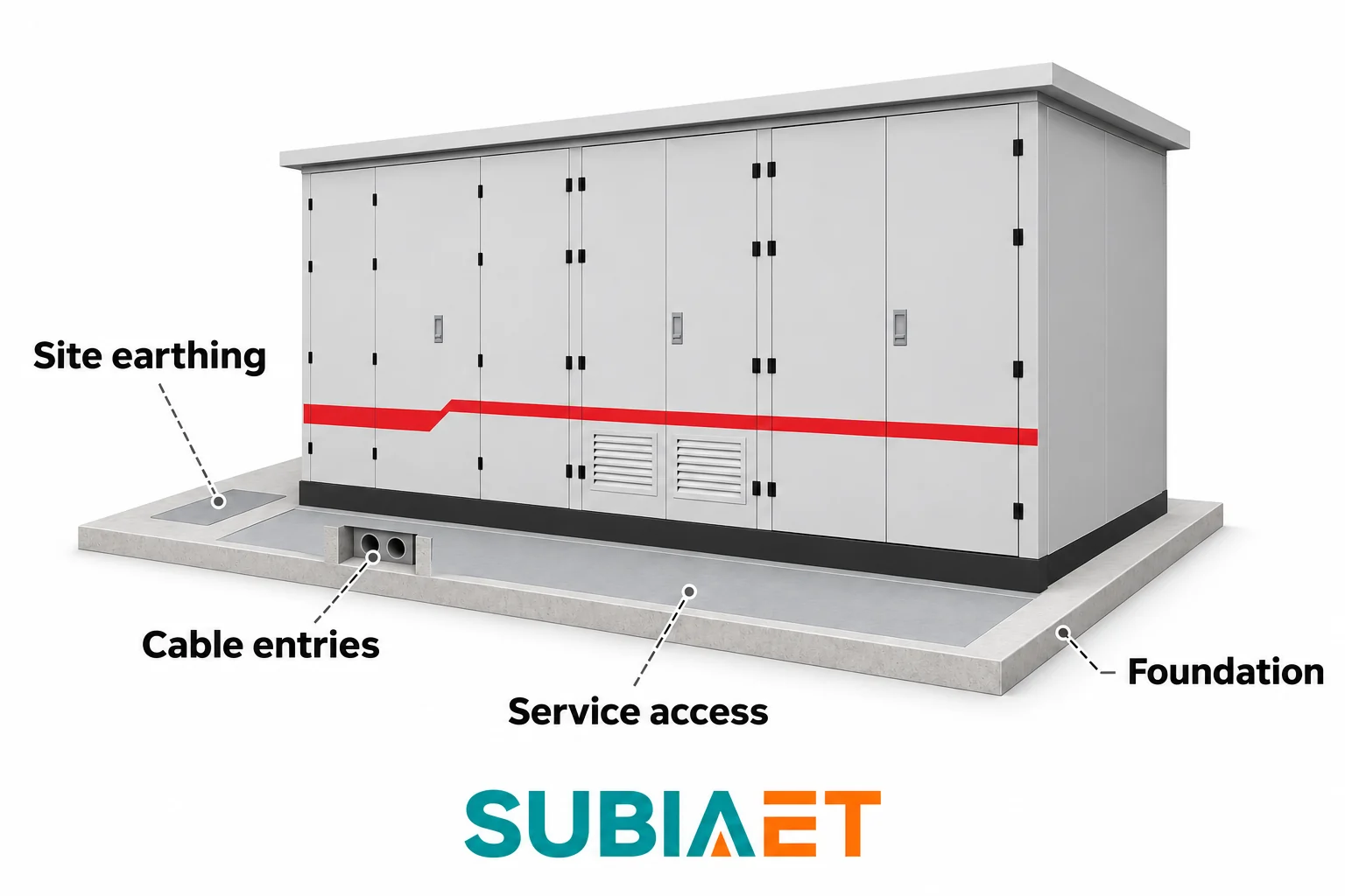
Even a tightly integrated prefabricated substation leaves a defined set of interfaces for site work. Understanding these interfaces is essential for procurement, civil engineering, and project coordination, because the boundary between the factory-prepared package and the site work must be agreed before detailed design begins.
Foundation and anchoring. The enclosure rests on a prepared civil foundation whose form depends on the enclosure geometry, ground conditions, and local practice. The foundation design addresses bearing, level support, drainage where required, and the specified anchoring loads, including wind or seismic requirements where applicable. The manufacturer’s foundation interface drawing and the site civil design together establish support dimensions, penetration positions and any anchor pattern. Some packages include a foundation or base; others require separate site construction. The scope must assign both supply and installation responsibility.
Cable entries. Cables arrive at the substation from two directions. On the MV side, the incoming supply cable from the network owner’s infrastructure connects at the designated MV entry point. On the LV side, the outgoing feeder cables leave through LV cable entries to reach downstream distribution points. The entry details—positions, cable sizes, number of parallel cables per phase, gland or duct termination method—are shown on the foundation or outline drawing and must be coordinated with the cable design. Ownership of the MV cable and the connection point varies by network owner and regional practice; this boundary is a commercial and technical matter that must be confirmed in the project scope documents.
Site earthing. Equipment protective-earth connections must interface with the project earthing design. The neutral treatment and any required separation or bonding arrangements are defined by that design, not by the enclosure shape. The external earth connection points on the enclosure are defined by the manufacturer, while the site earth electrode and interconnecting conductors must be included in the assigned project scope and meet the applicable requirements. Some arrangements also require an earth continuity conductor between the enclosure and specific equipment frames. The earthing design is a separate project deliverable and cannot be inferred from the substation outline alone.
Service and removal access. The enclosure must be positioned so that the access faces can be opened, cables can be terminated, and equipment can be serviced or eventually removed. For transformer-type substations, transformer withdrawal or replacement is an important logistics consideration; the site layout should include a clear path for heavy equipment movement. Service access requirements typically appear in the installation manual rather than the outline drawing, and they form part of the site planning inputs before the foundation is poured.
On-site commissioning. Even a fully factory-tested unit requires on-site inspection and commissioning checks before energization. Depending on the product, this may include verifying cable terminations, checking protective settings against the project protection coordination study, confirming earthing connections, inspecting for transport damage, and completing the network owner’s acceptance procedure. Some internal connections may be completed or verified at site. The agreed commissioning and acceptance procedure establishes the required checks and any hold points; a simple visual inspection does not replace them.
ABB’s compact substation manual illustrates equipment and site interfaces.
The key documents that govern these interfaces are the outline/foundation drawing (civil dimensions, penetrations, anchor points), the single-line diagram (electrical scope and boundary), and the project scope schedule (which side is responsible for which cable, earthing connection, and inspection step). Aligning these documents between the substation supplier and the site contractor is the practical starting point for avoiding rework.
For more on the transformer at the heart of the package, see the distribution transformer article. For the full SUBIA substation product range, the Substations and Prefabricated Cabin section covers the available configurations, including the YB Series and ZGS Series Prefabricated Substation options.
It changes the voltage between the connected circuits. In the illustrated package, separate MV and LV equipment handles the switching, protection and distribution functions specified for the project.
No. A transformer prefabricated substation can be designed for step-down or step-up duty. Confirm the intended power flow and equipment design before considering a different duty for an existing unit.
The manual operating position is inside the enclosure. For non-walk-in equipment the operating position is outside. Check the equipment documentation for maintenance access.
Use the project scope to identify what still needs installation and connection at the site. It should also assign responsibility for the site checks and commissioning before energization.
