Request a Quote
Share the equipment and project requirements. If you need help selecting a model, describe the application.
Have drawings or specifications? Email [email protected] with your project reference.

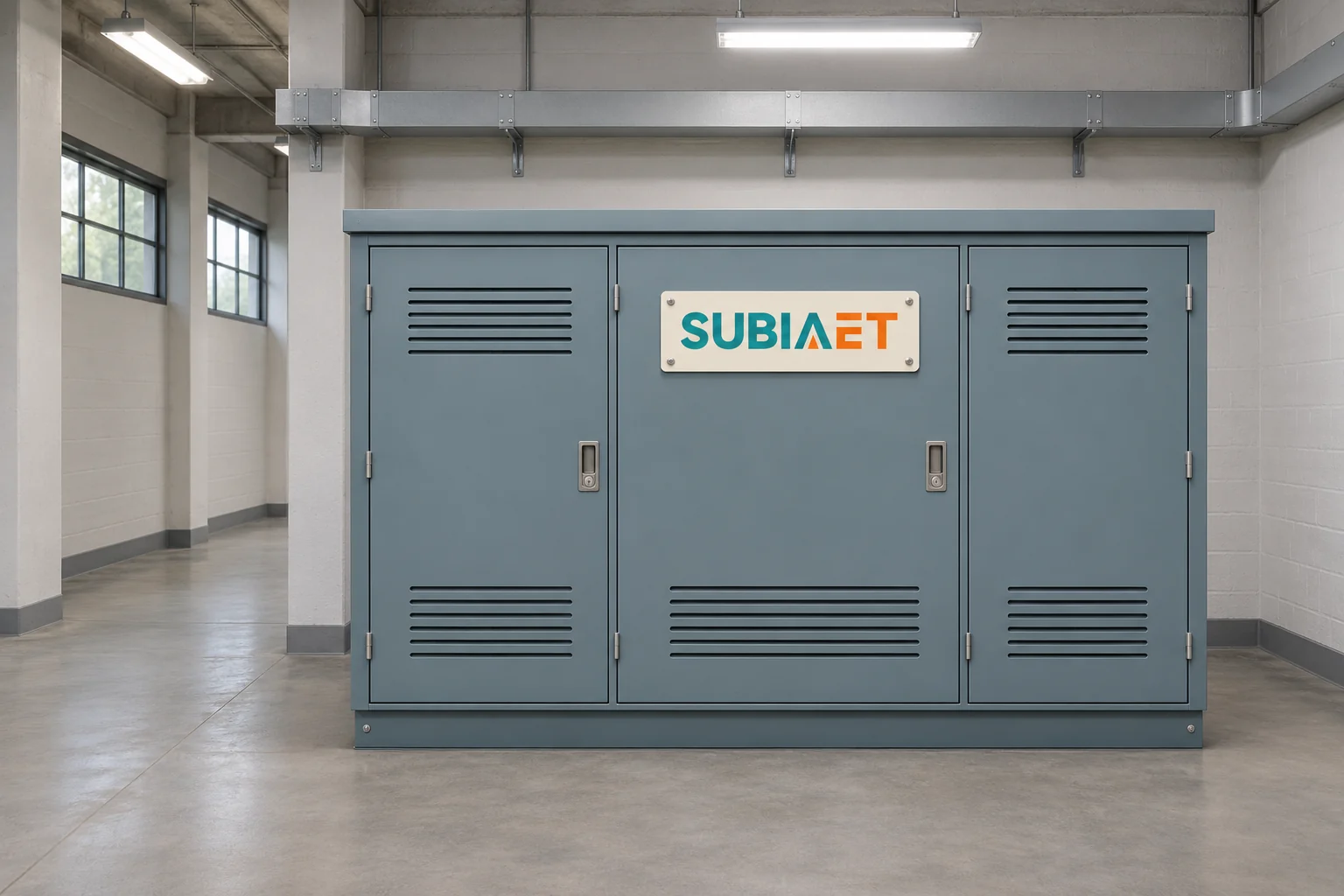
A distribution transformer is the transformer whose duty is to serve electrical load at the delivery end of the network: in a common load-serving arrangement it accepts medium voltage from a feeder and supplies the voltage needed by a customer’s installation or a local group of loads. Its identity comes from that role and from where it sits on the path between bulk transmission and the point of use — not from a single kVA figure, a particular enclosure style, or who happens to own it.
That distinction matters because practical questions about these units — how to describe the duty, where transformation is needed, and which project documents govern the interfaces — begin with their system position. Sizing still needs load data, and maintenance responsibility comes from the relevant agreements. Once you can place the unit on a single-line diagram, the ratings become a separate, answerable question instead of a vague one.
One possible path runs like this. A bulk transmission network carries power at high voltage toward a load centre. Substation transformers step it down through the voltage levels used by that network, until a distribution substation supplies the local medium-voltage feeders. Some networks use several transformation stages and others use fewer; no fixed cascade or global distribution-voltage band follows from the transformer label. From that substation, medium-voltage feeders run along streets, through industrial estates, or across a plant site. Along the feeder, a distribution transformer taps the medium-voltage conductor and steps it down to the low-voltage level used by appliances, lighting, motors and small equipment. From its secondary terminals the power goes to an LV panel or switchboard and then to final circuits.
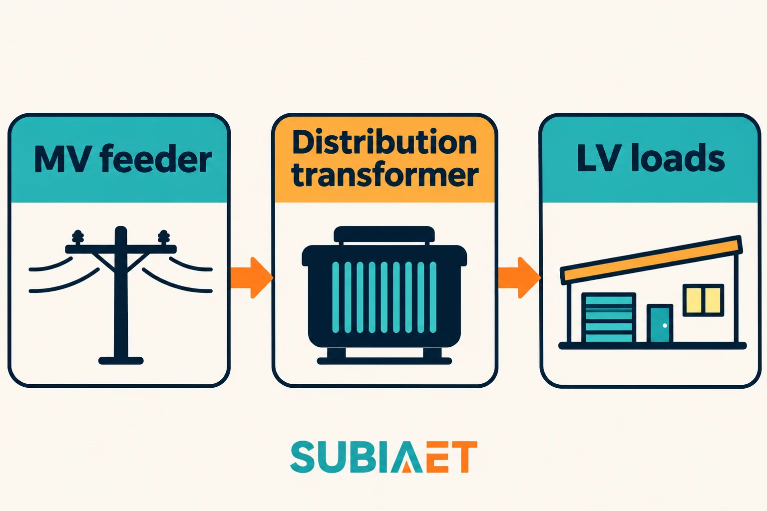
The transformer’s main function in that chain is voltage transformation. Its ideal voltage and corresponding load-current ratios are inverse, while a real unit also draws excitation current and supplies losses. It couples the circuits magnetically; circuit protection and switching are separate functions in the surrounding system.
What it does not do is equally important, because diagrams are frequently misread at this exact point. The voltage-transforming element is not the circuit’s fault interrupter or its maintenance-isolation device. Protective interruption, load switching and isolation are assigned to appropriately rated devices. These may include a feeder breaker at the substation, a specified switch or fuse arrangement on the transformer’s medium-voltage side, and breakers or fuses protecting outgoing low-voltage circuits. Each device has its own function: a load-break switch does not acquire short-circuit breaking capability merely because it is near a transformer. If a diagram shows a transformer symbol with a switching device beside it, the two are doing different jobs. Confusing them leads to incomplete equipment descriptions. A transformer supplier can include switching or protective devices in a package, so the correct question is which devices and ratings the package actually includes. The transformer symbol and the switching-device symbols still describe different functions.
The sequence above is the mainstream case, not a universal one. A plant that receives service at medium voltage may distribute at medium voltage internally and step down separately at each workshop, so several transformers sit at the same logical depth rather than in a neat cascade. A large facility may add transformation stages of its own — an internal 33 kV to 11 kV step before the load-serving units. A site with only medium-voltage process equipment may have no load-serving LV transformer at all on the main power path, only small auxiliary units for control and lighting. The role is still recognisable in these cases: trace the transformer’s output to the local distribution bus, switchboard or loads it serves. It need not connect directly to a final appliance to have a distribution duty.
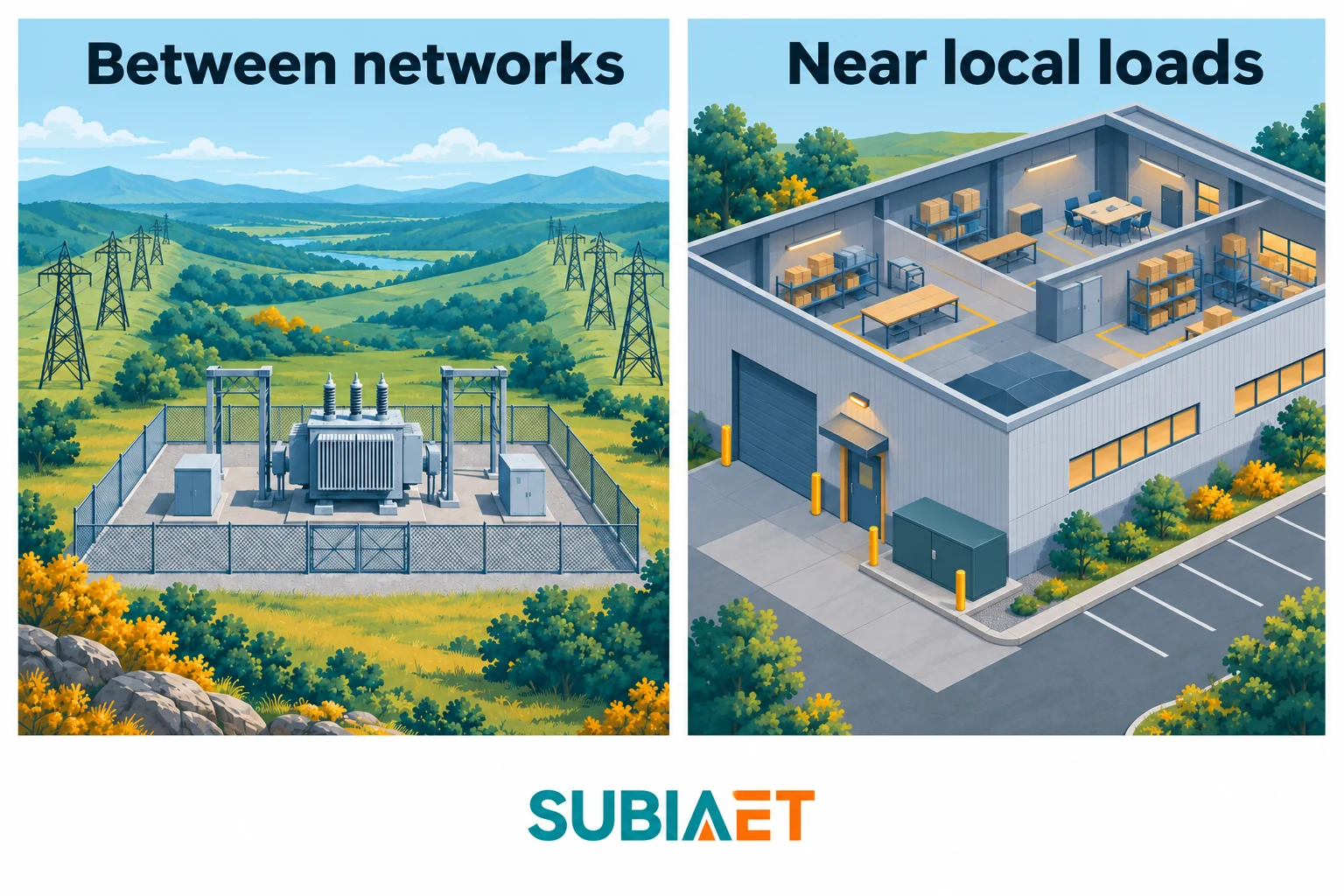
Consider two units and the difference becomes concrete.
The first example is a transformer at a 220/33 kV transmission substation feeding a regional network. Its required MVA and number of installed units follow that network’s demand and continuity plan. The design review includes specified impedance, loss evaluation and voltage-control requirements; on-load tap changing may be selected where voltage regulation while energized is needed. Protection, monitoring, fire provisions and any liquid containment are coordinated around the chosen equipment. A long outage could affect many downstream feeders, so the consequence of losing this unit is part of the network design.
The second example is an 11 kV/400 V unit serving a housing block or small workshop. Its pad, pole or other installation form depends on the design. A sealed liquid-filled construction can reduce exposure of the fluid to ambient air, but does not eliminate inspection and maintenance requirements. A coordinated MV fuse arrangement is one possible protection choice. An outage may affect a local group of customers rather than the whole regional network. Whether continuity relies on a spare transformer, an alternate feed or installed redundancy remains a project decision.
The duties differ in ways that shape design and procurement even when the underlying physics is identical. For a bulk-network unit with sustained high throughput, load loss, impedance and voltage-control capability can carry particular weight. For a distribution unit energized through long light-load periods, no-load loss can be significant, alongside cost, enclosure, siting and the daily or seasonal load pattern. Both loss components matter for both duties; the actual profile determines their weight. Some distribution designs use de-energized tap adjustment while others provide regulation under load. Documentation, tests and spares should follow the specified equipment and criticality rather than being inferred from either label.
The terminology needs care, because “power transformer” has two lives. In the IEC 60076-1:2011 public scope, power transformers are covered broadly: the family includes single-phase, three-phase and autotransformers, with stated exceptions. In that standards sense, “power transformer” is a family name that can encompass a distribution unit; it is not the opposite of one. In commercial usage, the market splits the same population by role — large transmission and substation units on one side, load-serving distribution units on the other — to describe the different application roles. Both usages are legitimate; mixing them in one sentence produces arguments about nothing.
What should not be imported from either usage is a size or voltage threshold. There is no universally agreed kVA at which a transformer stops being a distribution unit, and no voltage line that all networks respect. A 50 kVA unit and a 500 MVA unit can both fall inside a standard’s scope while sitting at opposite ends of the same system. Role and position separate them; nameplate numbers do not.
Step-down is the typical duty near loads, but it is not the only one in the category. Hitachi Energy, for instance, lists renewable step-up examples within its distribution transformer family — units that raise inverter or turbine output to a collection or connection voltage. That is a designed function of a specific product family, and it is a useful reminder that “distribution” describes where and why a unit sits, rather than one mandatory direction of real-power flow. It is not permission to reverse-feed an arbitrary transformer. Running a step-down unit backwards changes which winding absorbs energisation inrush, may put the tap range on the wrong side of the ratio, can leave current transformers and fuses sized for the forward direction, and may conflict with the intended terminal, earthing or protective arrangement. A step-up application calls for a unit specified for it.
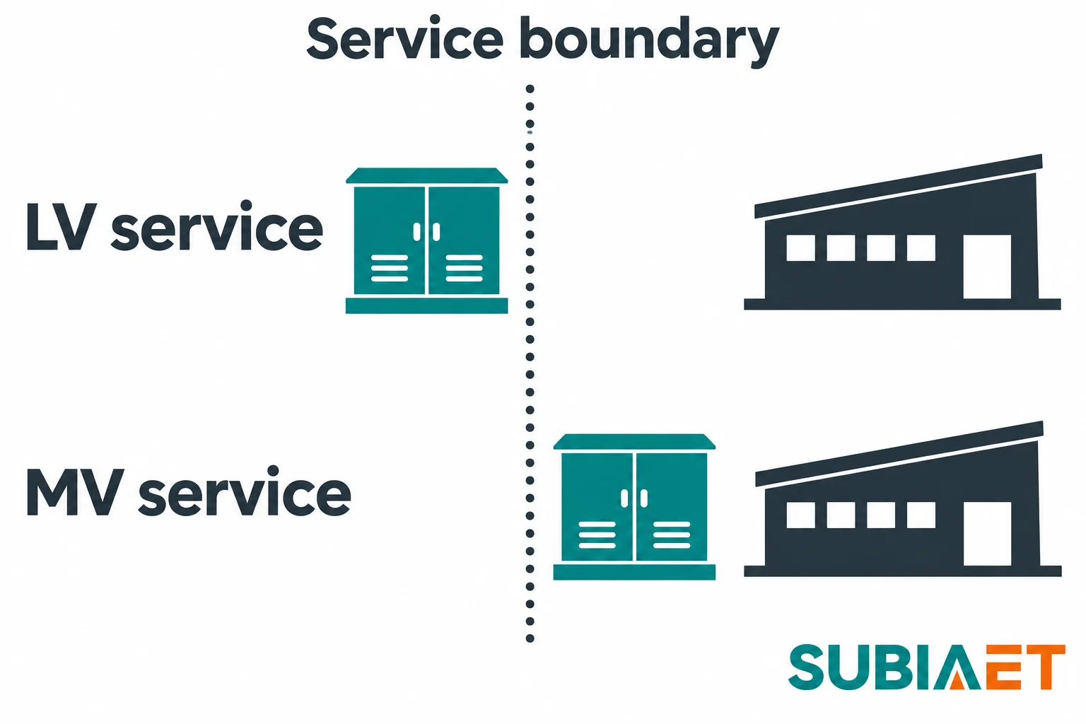
Two service arrangements explain most of the confusion about ownership.
In the low-voltage service example, the transformer sits upstream of the service handoff. The customer receives LV at the interface and can feed a main LV switchboard. In the medium-voltage service example, the handoff happens at MV, and a downstream transformer supplies any LV loads within the facility. These positions establish where the voltage change occurs; they do not by themselves prove who owns the equipment, where the meter sits or whose land it occupies.
These are pictures of position, not rules about ownership, metering, grounding or protection. Which side of the line the transformer falls on, who reads the meter, where the neutral is earthed, and which protection function trips what are all matters of the utility agreement and the local code — and they change between networks and between projects on the same network. The Oak Ridge National Laboratory industrial electrification guide, Appendix F, illustrates facility power systems with distribution feeders, switchgear and transformer stages. The service agreement establishes the ownership and responsibility boundary for a particular site. The same diagram also shows why a facility is rarely uniform. Some loads take medium voltage directly, where the process and distribution design call for an MV supply; others are served through a further step-down stage. This is how a medium-voltage load bypasses the LV transformer entirely: it connects to the medium-voltage bus, so the load-serving transformer that feeds the rest of the site is simply not in its path.
For a project team, the practical consequence is that the phrase “our transformer” is ambiguous until the boundary is drawn. A facility engineer describing a unit as theirs may mean a transformer they maintain, a transformer they paid for but the utility operates, or a transformer on their single-line diagram that belongs to somebody else. Marking the service handoff on the drawing and checking the agreement makes the position and the responsibility clear together.
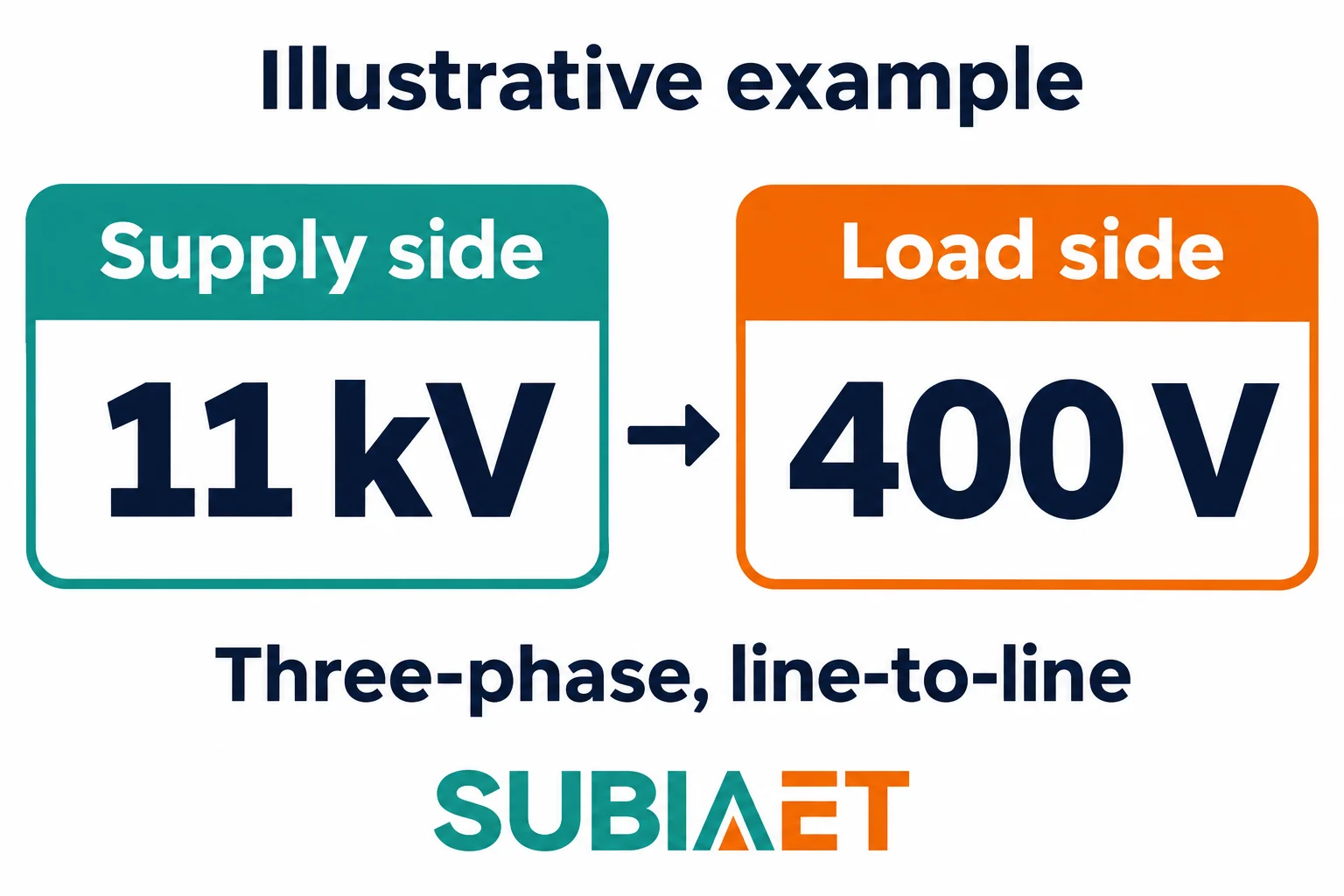
The Odisha Electricity Regulatory Commission’s distribution planning document describes a three-phase 11/0.4 kV distribution transformer arrangement. It provides a concrete voltage pair for reading a system diagram: 11 kV on the primary side and 0.4 kV, or 400 V, on the secondary side.
In this example, 11 kV and 400 V are the rated line-to-line quantities. “11 kV” states the nominal voltage of the supplying three-phase system, not the exact voltage present at the terminals on any given afternoon; feeder voltage moves with tap position, source voltage and loading. “0.4 kV” and “400 V” are the same value written two ways. On a balanced 400 V wye secondary with the neutral brought out, the line-to-neutral voltage is 400 ÷ √3 ≈ 231 V, commonly paired with the nominal 230 V label. That relationship requires the stated connection and neutral; it cannot be inferred from every 400 V secondary. Suitable single-phase loads may use a phase-neutral pair, while three-phase loads use all three lines.
The load-side voltage says nothing about capacity. A transformer with a 400 V secondary could be rated at 100 kVA or at several megavolt-amperes; the voltage describes the ratio, while kVA states apparent-power capacity under the specified rating conditions. Eaton’s transformer fundamentals treats voltage and kVA as separate ratings — a unit giving the right voltage and the wrong kVA is simply the wrong unit, and the mistake is invisible if you read only half the nameplate.
Nor is 11 kV / 400 V a regional standard that travels. Some networks distribute at 10 kV, 13.8 kV, 20 kV or 33 kV; low-voltage utilization may be quoted as 380 V, 400 V or 415 V according to the network’s nominal-voltage convention. Actual voltage at a load also depends on the installation’s voltage drop. Actual supply and utilization voltages depend on the network and on the installation design — cable length, conductor size, motor starting, and the tap setting chosen at commissioning all move the number at the socket without changing what the transformer is.
Before writing a sentence about a specific unit — in a report, a tender clarification or a maintenance plan — work through the diagram and the nameplate in this order.
First, establish position and direction. On the single-line diagram, identify what is upstream and what is downstream, and which winding is the supply. “HV side” and “supply side” are not synonyms on a step-up unit, and a diagram read backwards produces a wrong description of the entire installation.
Second, confirm the electrical identity: the voltage ratio and its tap range, the number of phases, the winding connection and vector group, and the system frequency. Frequency is not a formality — operating at a different frequency with the same applied voltage changes the volts-per-hertz relationship and can change flux, losses and impedance behaviour, and its suitability is a design question rather than a labelling one.
Third, read the rating as a set of conditions rather than a single number: rated power in kVA, the temperature rise and cooling basis under which that rating applies, impedance, insulation level, and the loss figures. If the manufacturer specifies separate natural-air and forced-air ratings, those values describe different cooling conditions; fitting fans alone does not establish a new rating.
Fourth, separate the questions that the transformer cannot answer. Capacity requires load data: connected load, diversity, starting currents, harmonic content from drives or inverters, expected growth, and the ambient and altitude at the site. Siting and enclosure require their own checks — pole-mounted, pad-mounted, indoor or underground, with ventilation, fire provisions, any liquid containment, cable termination space and maintenance access coordinated with both the site and the selected design. Construction follows from those answers: a liquid-filled proposal must address its fluid and enclosure requirements; a dry-type or cast-resin proposal must still provide suitable ventilation or another designed heat path. Neither construction label alone establishes suitability or economy. Deeper classification — by insulation, phase count and installation — and the demand arithmetic behind a sizing decision belong to their own treatments.
If you are establishing what kind of unit you are looking at, the transformer overview and the classification by function, insulation, phase and installation are the natural next reads. If you already know the role and need to choose a construction, the oil-immersed and dry-type family pages cover the two main branches, and the power transformer page covers large network units. If the question is capacity rather than type, the factory-expansion sizing walkthrough shows how load data becomes a kVA figure. For utility-side applications, the secondary distribution page describes the load-serving case directly. And if the mechanism itself is still unclear, start from how a transformer works.
No. A distribution transformer is described by its duty in the local distribution system. kVA tells you its rated apparent-power capacity. Look at the feeder and the circuits the transformer serves to identify the duty.
Check the utility agreement. The service voltage and single-line diagram help locate the transformer relative to the handoff, while the agreement determines which party owns or maintains it.
A transformer serving distributed generation may raise the source voltage to match a collection or connection network. Some manufacturers include these purpose-designed units in their distribution ranges. Specify the intended direction of service and verify the design for it.
No. The example specifies rated voltages of 11 kV and 400 V between phases. The kVA rating must be checked separately to determine the unit’s apparent-power capacity under its specified conditions.
