Request a Quote
Share the equipment and project requirements. If you need help selecting a model, describe the application.
Have drawings or specifications? Email [email protected] with your project reference.

A transformer feeder is a short piece of the network with an unusually concentrated set of duties: it carries the transformer’s continuous current, it must ride through the specified energisation duty, the protection must clear faults within the required withstand and clearing limits, and the project needs approved isolation, earthing and recovery arrangements. Two well-established architectures deliver those duties: a three-pole switch-fuse functional combination, or a circuit breaker with a relay that senses, decides and commands a trip.
Compare what each offer can demonstrate against your actual network and transformer, whether it covers the fault range you have, coordinates with the devices on either side of it, and can be accepted with the evidence supplied. The decisive conditions are the credible duty range at the feeder position, the sensitivity required for low-current faults, and the completeness of the sensing-to-interruption chain in each proposal.
Start by separating the word on the nameplate from the work the position has to do. In this medium-voltage to low-voltage (MV/LV) distribution example, MV is the supply side of the step-down transformer and LV is the downstream distribution side. The MV transformer feeder sits between an MV busbar or ring and the transformer primary; the LV board sits on the transformer secondary.
At that MV position the duties are these, and every offer should be measured against all of them rather than against one:
Two consequences follow. First, an apparatus name is not a scheme. “Circuit breaker” identifies an interrupting device; IEC 62271-100:2021 with Amendment 1:2024 applies to in-scope three-phase AC circuit breakers and treats the breaker as the interruption apparatus — but a complete feeder protection scheme also needs its own sensing, decision and tripping arrangements. A breaker cabinet without a specified relay, sensors and trip energy is not a protection proposal. Second, the switch-fuse option is not “a switch”. IEC 62271-105:2021 covers a specified class of three-pole AC switch-fuse functional assemblies in which switches or switch-disconnectors are paired with current-limiting fuse-links, and the making and breaking capabilities belong to the rated functional combination — not to the switch on its own.
Keep the scope identical across both offers before comparing anything: the same transformer, the same source impedance and fault-level range, the same earthing, the same LV board and its main device, the same load profile, and the same operating and interface requirements. Only then do the two offers become comparable rather than two different projects.
A switch-fuse combination is a functional assembly, and the correct mental model is a division of labour inside that assembly rather than a single device doing everything.
The switch-disconnector carries and switches load current and provides the isolation function. The fuse-link interrupts within its declared breaking range. In its current-limiting region, it reduces the peak let-through current relative to the prospective current. The link between the two is mechanical. A fuse striker, when the element operates, releases a pin that strikes the switch mechanism, initiating opening of all three switch poles in the documented arrangement.
That three-pole striker operation matters more than it first appears. Opening all three poles avoids leaving the remaining phases connected after one fuse operates. Verify the striker action for the exact supported combination and use the separate approved means of isolation for work.
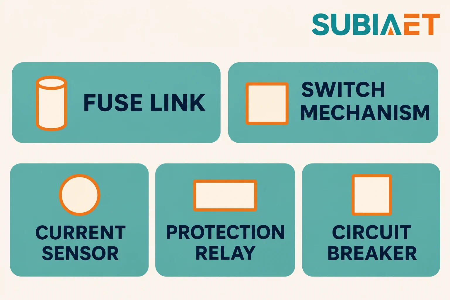
The figure compares the functional elements in the two schemes. The fuse-link responds to current and its striker can initiate switch opening. The sensor, relay and breaker perform separate functions in the relay scheme. The figure shows equipment roles without a wiring or fault-current path.
Optional features belong to a proposal only when they are written into it: motor operation of the switch, auxiliary contacts for position indication, a shunt trip coil, an integral earthing switch, key interlocks, remote status contacts. An RMU or switchgear lineup that can be configured with these is not evidence that a particular offer includes them. Ask for the equipment bill, not the catalogue family.
The scope distinction is where most confusion originates. A switch-disconnector alone has its own load-breaking capability and its own isolation duty, and is a perfectly sound device. It is not the combination. The rated fault-making and fault-breaking capability of a switch-fuse assembly belongs to the assembly as tested and declared — this is the boundary the switch alone does not cross.
The fuse does not do all the interrupting, and the switch does not do all the interrupting. Which one does the work depends on the current, and the crossover is what the industry calls the transfer current.
The ABB medium-voltage fuses technical guide, section 4.6 explains the change in duty near the transfer current. A fuse striker can initiate switch operation. Around the transfer current the duty allocation changes: above it, the fuses interrupt the other poles before the switch interrupts; below it, the opened switch may clear the remaining phases. That description alone tells you why transfer current cannot be read off a general table. It is not a property of the fuse, and not a property of the switch. It is a property of the pair — the fuse characteristic and the switch timing acting together — and it has to be checked against the combination’s declared transfer rating and the applicable use conditions.
Four things get conflated in offers, and they should be kept apart:
Three practical checks follow, and none of them require you to calculate or select a fuse:
What to request from the vendor is therefore specific: the exact fuse manufacturer, type, curve reference and striker designation that the combination is approved with; the evaluated transfer current for the exact pair and the rated transfer-current limit it must meet; the declared fuse breaking range; the thermal verification for the application conditions; confirmation of the approved assembly status; and the spare fuse list by rating. If any of those is answered with a family name rather than an exact reference, the offer is not yet evidence.
The relay-breaker architecture splits the functions that the switch-fuse assembly combines. That split is the source of both its flexibility and its failure modes, because each link in the chain can be individually adequate and the chain still be incomplete.
The chain runs like this. Current transformers or other sensors measure the primary current and reproduce it at a usable level. The relay compares what it measures against its protection functions, applies its logic and time delays, and — when a function operates — energises a binary output. The relay output signals the specified trip circuit, which energises the breaker’s trip coil or actuator. The coil releases the breaker’s latch, stored energy in the mechanism (spring, or in some designs the same actuator) drives the contacts apart, and the arc is extinguished in the interrupter. Auxiliary contacts then report the new position, and status is signalled onward.
An example of this separation is documented in the ABB RET615 application manual, configuration B: a transformer protection relay configuration uses current-sensing inputs and a separate output to the high-voltage circuit breaker trip coil, with other outputs reserved for backup or indications. What that illustrates is the distinction between measuring, deciding, signalling and interrupting — four different things, in four different places, that a proposal must specify individually.
Check the complete trip-energy path. A separately supplied design can use an auxiliary DC source and supervision as specified. Other designs use self-powered relays, as illustrated by the Schneider Electric installation guide. Check the proposed arrangement’s start-up and operating limits, what supplies the actuator and whether that energy is available at the minimum fault condition of interest. Include the specified monitoring and response to a lost supply.
Low earth-fault sensitivity can determine whether either proposal meets the feeder duties. It depends on four things acting together:
None of that makes relay-breakers automatically suitable. It means that the claim “the relay handles earth faults” has to be supported by a demonstration for the actual chain: the actual sensor, the actual relay range, the actual energy source, at the actual minimum earth-fault current your earthing design produces. And because detection is not clearing, the offer must state the complete clearing time — sensing, relay operating time, trip coil energisation, breaker opening and arc extinction — not just the relay’s setting time. That total is what has to fit under the transformer’s withstand and the upstream device’s timing.
Local and remote reporting — position, trip indication, alarm, measurement — is a specification item, not a default. If the project needs a status interface to a control system, it is a requirement in both offers, and it is a requirement the switch-fuse offer may need an additional device to satisfy.
A protection study for this comparison uses the same inputs regardless of which architecture is being evaluated. On the transformer side: rated power and rated current, impedance and its tolerance, vector group and winding connections, tapping range, cooling class, allowable continuous loading and the cyclic duty, through-fault withstand, and the magnetising inrush envelope for energisation from the source side. On the network side: source fault level and its credible range across operating states, cable and line impedances to the feeder, upstream device type and its characteristic, the earthing method and its impedance, and the LV board with its main device and the loads behind it. If the transformer impedance data is not yet fixed, the fault currents are not yet fixed either, and neither offer can be evaluated; the relationship between impedance, fault current and voltage drop is worth settling before the protection comparison rather than after.
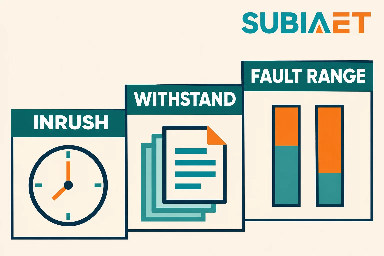
The figure separates three evidence windows that are often treated as one. They answer different questions and no single number satisfies all three.
Inrush. Energising a transformer draws a large, asymmetric, decaying current rich in second and higher harmonics. It is not a fault, its magnitude and duration vary by energisation condition, and both options must ride through the expected envelope. For a relay scheme, the evidence is that the chosen protection functions will not operate on the actual inrush envelope of this transformer, with the actual sensor arrangement and the actual restraint method. For a fuse, the evidence is that the exact link’s characteristic tolerates the expected repeated energisation duty without inappropriate operation or damage, as supported by the application evidence. These are not equivalent proofs, and neither is satisfied by a generic multiplier. The inrush envelope is transformer-specific and depends on the point on the voltage wave at closing, the residual flux, and the source impedance.
Withstand. For any fault that persists, the transformer is being heated and mechanically stressed. The protection must clear before the withstand is exceeded, and the comparison has to be made at the actual fault current and the actual clearing time of the proposed device — which, again, is a chain quantity for the relay-breaker and a curve quantity for the fuse. Overload is a separate path: a relay scheme can carry a dedicated overload function distinct from its short-circuit functions, while the fuse combination and any assigned LV device must show which path covers overloads and lower-current faults. A fuse-link’s short-circuit breaking range alone does not establish overload protection. That difference changes how the feeder behaves under sustained overload and under a modest fault, and it belongs in the comparison.
Fault range. There are two ends here and they are not symmetric. At the top end the question is interruption: can the device interrupt the maximum prospective fault under the declared conditions? Separately verify peak making duty and any specified short-time withstand of the relevant equipment. At the bottom end the question is detection: what is the smallest fault current the proposal will recognise and clear, and does the project’s earthing design produce at least that much? A low-level earth fault can be the limiting detection case on an impedance-earthed system.
One further step is easy to get wrong: viewing the fault current across the transformer. The corresponding current at the MV feeder depends on the fault type and the network model. Winding connections and earthing determine which sequence components cross the transformer, so an earth fault on the LV side of a delta-wye transformer does not simply appear at the MV terminals divided by the turns ratio. Reflect the transformer’s winding arrangement and the system earthing in the project network model rather than applying a universal ratio conversion, and derive the earth-fault currents from the model.
Coordination is not a separate exercise from the study above; it is what the study produces once the devices are fixed. It answers one question: for every fault within the agreed range, which device operates, and does the rest of the system remain in service?
The mechanics are straightforward, the tolerances are where projects fail. Everything must be placed on a common basis — one voltage and one current reference — before any curves are compared. A device curve quoted at LV and a device curve quoted at MV cannot be laid over one another directly. Once on a common base, four things have to be superimposed honestly:
Three different questions are routinely mistaken for one another:
Coordination with the LV main device is the part that most often needs the transformer in the model. The LV device sees LV fault current; the MV device sees the corresponding MV current. Whether the two curves align depends on the transformer’s impedance, its vector group and the earthing, and on whether the fault is a three-phase fault, a phase-to-phase fault, or an earth fault. Use the project network model with the actual winding connections and grounding; do not substitute a nominal ratio conversion, and do not assume that a selectivity result established for three-phase faults transfers to earth faults.
Consider this fictional comparison. A single MV radial feeder supplies one transformer, which feeds one LV board. The transformer rating, impedance, vector group and earthing are fixed for both offers, as are the source fault-level range, the LV main device and the load profile. Two requirements are agreed before the offers are opened: the credible duty range at the feeder position, covering phase and earth faults from the minimum the network can produce in the relevant operating state to the maximum prospective fault level; and an explicit requirement to detect and clear low-level earth faults on the impedance-earthed system, together with a trip and status interface to the plant monitoring system.
Offer A is a switch-fuse combination in an RMU-type arrangement, with an integral earthing switch. Offer B is a relay and circuit breaker arrangement at the same position, with current sensors, a protection relay and a DC trip supply.
The figure places two proposal folders beside the same transformer. It deliberately carries no circuit topology, no current arrows and no performance claim: the only thing it establishes is that the comparison is between two ways of protecting the same transformer, not two transformers.
| Requirement | Offer A evidence | Offer B evidence | Open check |
|---|---|---|---|
| Rated load switching and continuous current | Switch rating and the exact fuse link rated current, with thermal verification for the enclosure and ambient conditions | Breaker rating and the continuous current rating of the current path, including sensors | Confirm both are rated for the actual cyclic duty, not just the nominal transformer current |
| Phase-fault interruption across the agreed duty range | Declared combination rating and the exact fuse characteristic covering the upper part of the range | Breaker rated short-circuit breaking current and making capacity, with the relay’s phase overcurrent functions | Check the low, intermediate and maximum studied phase faults, including each applicable switch/fuse duty region and the breaker’s declared duty |
| Low earth-fault detection and clearing | Not demonstrated. The quoted evidence does not demonstrate clearing within the required time at the modelled minimum earth-fault current, and no additional path is offered | Claimed, conditional: sensor arrangement, relay earth-fault function and its range, trip energy at that current, and total clearing time still to be shown | Require a demonstration for the actual chain at the actual minimum earth-fault current before accepting either claim |
| Isolation and earthing provision | Switch-disconnector isolation plus integral earthing switch, subject to the offered interlocks and the operating procedure | Breaker position alone does not isolate; need the disconnector or withdrawable position and the earthing arrangement | Confirm the isolation and earthing means are in the equipment bill, not assumed from the architecture |
| Coordination with upstream and LV devices | Fuse curves and tolerances against the upstream device and the LV main device, on a common base, within the range where the fuse is the intended clearing device | Relay characteristics, CT error, breaker opening time and tolerances against the same devices, including the earth-fault case | Check both against the actual winding connections and earthing; a three-phase result does not transfer to earth faults |
| Trip and status interface to monitoring | Requires an additional device or a specified auxiliary arrangement; not shown in the base offer | Relay binary outputs and communication, conditional on the specified interface being in scope | Resolve who supplies the interface, its protocol, and the point list, in writing |
The result is instructive precisely because it is not a clean win for either side. On the base duty — load switching, phase-fault interruption across the agreed range, isolation and earthing — the approved switch-fuse combination can be a fully acceptable answer, provided the exact pair, its transfer current, its minimum breaking current and its thermal verification are all supplied and all cover the study. On the added requirement — low earth-fault detection and clearing with a monitoring interface — Offer A has not demonstrated coverage, and cannot be made to cover it by assertion; it would need either verified coverage for the proposed combination or an approved additional detection and clearing path with its scope stated.
Offer B is a candidate, not a winner. It satisfies the requirement on paper only if the sensors can resolve the minimum earth-fault current, the relay’s earth-fault function covers that range, the trip energy source is available and supervised under exactly that condition, the total clearing time fits under the transformer withstand and the upstream device’s timing, and the interface is specified. Each of those is a checkable item, and the offer should carry the evidence rather than the intention.
The way to make this comparison decidable is to issue one return package specification to both bidders, so that the answers arrive in the same shape.

The figure groups the return package into four document sets. Those four sets are the minimum that makes two offers comparable.
Common system study inputs. Single-line diagram of the feeder and its neighbours; source fault level and the credible range across operating states; system earthing method and its impedance; cable and line data from the source to the feeder and from the feeder to the transformer; upstream device type and characteristic; transformer data including rated power, rated currents, impedance and tolerance, vector group, tapping range, cooling class, through-fault withstand and the inrush envelope; the LV board, its main device and its characteristic; the load profile and the operating modes.
Exact equipment bill and documents. For a switch-fuse offer: the switch type and ratings, exact fuse and striker designation, its curves, evidence of the supported pairing, the evaluated transfer current and declared limit, and the applicable fuse breaking range, the thermal verification for the application conditions, and the earthing switch and interlock details. For a relay-breaker offer: the breaker type and full ratings, the sensor types with ratios and accuracy, the relay type with the list of protection functions and their ranges, the trip coil data, the auxiliary supply arrangement and its supervision, and the self-powered behaviour if applicable. In both cases: the routine test certificates for the actual equipment supplied, not a family brochure.
Scope, drawings and trip energy. What the offer includes and, more importantly, what it excludes — earthing switch, motor operation, auxiliary contacts, relay, sensors, DC supply and battery, interpanel wiring, testing, spares. Then the schematic and wiring drawings, terminal allocation, and a specific account of the trip energy path with its monitoring. A one-line diagram plus a catalogue page is not a scope definition.
Acceptance and test plan, plus restoration policy. What will be demonstrated and how: routine tests on the equipment, factory acceptance testing of the assembly, relay function testing against the specified functions, primary injection testing where offered, and a functional test of the sensing-to-opening and status path under agreed test conditions. Check fault-interruption capability separately against the applicable ratings and verification evidence. Then the restoration policy: which spare fuses by rating, which spare relay or trip coil, what the expected restoration time is after an operation, what training is provided, and what stocking commitment accompanies the offer.
These related references help prepare the return package. The transformer impedance relationship that drives the fault-current inputs is set out in transformer impedance explained: fault current, voltage drop and selection. The feeder arrangement itself — how an RMU position is configured and what sits in it — is covered in what is a ring main unit and how it works in secondary distribution, while the product family scope and the configurations available around these positions are on the medium voltage switchgear page. Terminal and connector scope, which is a separate question from protection, is treated in pad-mounted transformer interfaces: radial or loop feed, deadfront or livefront. And when the question shifts from protection selection to accepting the delivered assembly, the boundary between assembly testing and apparatus testing is set out in substation FAT vs transformer tests: which evidence covers the complete package.
No. The transformer rating sets the continuous current and, together with its impedance, part of the fault current, but it does not decide the architecture. What decides it is the credible fault range at the feeder position — especially the minimum earth-fault current produced by the network earthing — the transformer’s through-fault withstand and inrush envelope, the tolerances of the devices on either side, and whether the offer can demonstrate a complete sensing-to-interruption chain for the requirements you actually have. Two transformers of identical rating on differently earthed networks with different source impedances can produce two different correct answers. Use the rating as an input to the study, not as a substitute for it.
Not for the combination’s rated fault duty. A switch-disconnector is rated for load switching and for isolation, and it performs both duties well. But IEC 62271-105:2021 covers three-pole AC switch-fuse functional assemblies in which switches or switch-disconnectors are paired with current-limiting fuse-links, and the making and breaking capabilities belong to that rated functional combination — not to the switch alone. Removing or omitting the fuse-links and treating the switch as the fault interrupter crosses a boundary the switch’s own rating does not cover. Conversely, adding fuse-links to a switch does not create an approved combination unless the specific pair is approved together.
Transfer current describes the changeover in clearing duty between the fuse-links and the switch in a specified combination. The ABB medium-voltage fuses technical guide explains it in Section 4.6 (printed pp. 22–23): around the transfer current the duty allocation changes — above it, the fuses interrupt the other poles before the switch interrupts; below it, the opened switch may clear the remaining phases. Because the switch’s opening timing and the fuse’s characteristic both enter the result, the value belongs to the specific pair and has to be checked against the combination’s declared transfer rating and the applicable use conditions. It is also a different question from the fuse’s minimum breaking current, which the same guide treats separately.
It may not, and the offer has to prove that it does rather than assume it. Impedance earthing can limit the available earth-fault current. A suitably applied relay scheme can address a lower-current duty where the fuse combination cannot demonstrate clearing in the required time. If the exact combination cannot demonstrate clearing across the required range, request a verified alternative path. Either the requirement is met by an approved combination whose declared characteristics cover it, or an independent additional detection and trip path is needed.
Put both devices on one time-current plot on a common voltage and current base, with published tolerances rather than nominal lines, and with the actual clearing time of each interrupting device — including breaker travel and arc extinction, not just the relay setting time. Then check that the result holds for the fault types you care about, not only for three-phase faults. Earth faults require the transformer’s winding connections and system earthing to be in the network model, because zero-sequence quantities do not transfer across a delta winding the way positive-sequence current does; a nominal ratio conversion will give you a coordination result that does not correspond to the plant. Finally, state separately which device is intended to interrupt in each current region, so that selectivity and interruption are not conflated in the same sentence.
