Request a Quote
Share the equipment and project requirements. If you need help selecting a model, describe the application.
Have drawings or specifications? Email [email protected] with your project reference.

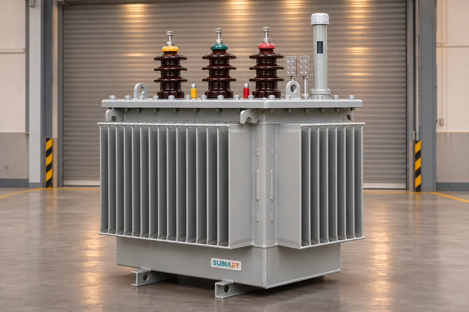
Receiving two transformer offers that differ only in winding conductor material looks simple until you try to put them side by side. The conductor material is one property among dozens that determine how a transformer performs, how it fits in your installation, and what it will cost to run. Neither copper nor aluminum automatically wins. What you need is a disciplined process: establish a single common duty, verify which figures share a comparable basis, and identify what is still missing before you can award with confidence.
This article walks through each step in that process, using a fictional same-duty example to show concretely what can be decided today, what must be requested, and why a lower headline price or a single favorable loss number does not settle the comparison.
The fundamental relationship is R = ρℓ/A, where ρ is the resistivity of the conductor material, ℓ is its length, and A is its cross-sectional area. Copper has lower resistivity than aluminum. If you hold the conductor geometry and temperature constant, an aluminum conductor of the same cross-section as a copper conductor will have higher resistance and therefore higher winding I²R loss at the same current. The practical response, as the Hammond Power Solutions technical note explains, is that transformer designers increase the aluminum conductor cross-section to compensate for its lower conductivity. A larger cross-section A reduces resistance toward the target, with ρ, ℓ, and operating temperature each playing a role in where the design lands.
This adjustment is not a simple multiplier. The conductor alloy, the form used (wire, strip, or foil), the coil geometry, the insulation around each turn, the cooling duct arrangement, and the structural bracing and clamping are all distinct design choices that interact with each other. The Eaton Cooper Power Series reference note comparing three-phase 2,500 kVA pad-mounted designs illustrates this in a documented example: all-aluminum, all-copper, and copper-primary/aluminum-secondary designs share the same rating and voltage connection in Eaton’s 2016 example. At 50% load, all three designs reported the same rounded efficiency, while full-load efficiencies, no-load losses, load losses, and outside dimensions differed between configurations. This tells you something important: a material substitution at the same voltage and kVA rating does not simply produce a heavier or lighter version of the same coil, nor does it establish a universal efficiency or size ordering.
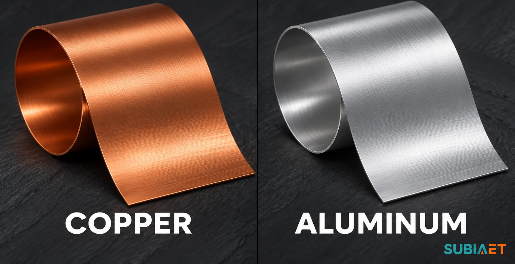
For procurement, the finished transformer’s routine report can document measured winding resistance, test temperature and any applicable reference correction. Check the contractual acceptance criteria for each reported value and keep the load-loss guarantee separate. When two suppliers offer different conductor materials, they are proposing different designs, not interchangeable copies of a single design with one element swapped. The comparison must be conducted on the complete offered units, not on conductor resistivity tables.
Before any figure from one offer can be compared to its counterpart in another, every element of the electrical and installation duty must be fixed and shared. An ambiguous requirement can put the two quotes on different bases. Resolve it before ranking affected figures.
The duty specification needs to cover, at minimum:
That last point deserves particular attention. HV and LV windings can use different conductor materials, as the Eaton example shows. The Horizon Power distribution transformer specification permits copper or aluminum alternatives in its own procurement and requires disclosure of the winding material, construction, processes and clamping. When either conductor is acceptable, your tender document should say so explicitly rather than leaving it implied, and each offer should declare the HV and LV material independently rather than simply stating “copper” or “aluminum” at the transformer level.
If a supplier proposes a deviation from any of the duty parameters, that deviation should be listed explicitly and evaluated separately. Comparing a sealed ONAN unit against a conservator-type unit, or comparing a 4% impedance design against a 5% design, without acknowledging the difference will produce a meaningless result.
Loss figures are among the most commercially sensitive numbers in a transformer comparison, and they are also among the most frequently mismatched. Two numbers that appear in adjacent cells of a comparison spreadsheet may have been measured under different conditions and cannot be directly compared.
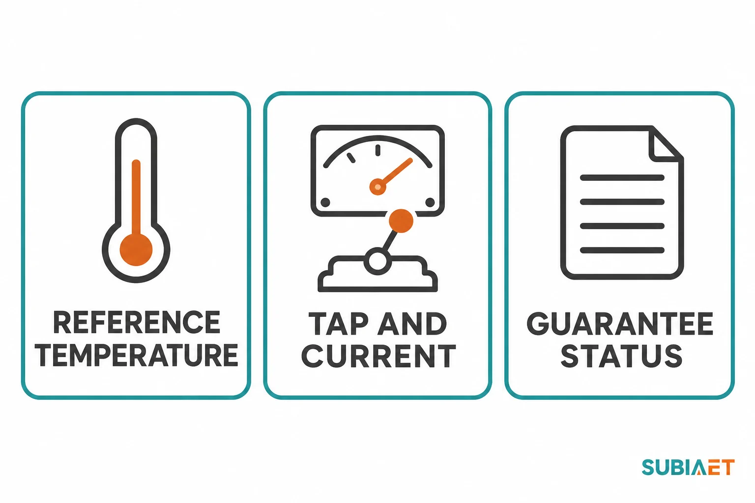
No-load loss is measured at the rated excitation voltage and rated frequency, with the transformer unloaded. The core and excitation design are the main drivers. The winding material label alone gives no reliable ranking. To compare no-load loss figures across two offers, you need to confirm: the excitation voltage and frequency used, which tap was energized, and the test connection. Compare guarantees on the same basis first. Check supporting measurements and corrections when the test reports are available.
Load loss is a combined figure that includes winding I²R losses and additional AC and stray losses—eddy currents in the winding conductors, stray losses in structural parts, and so on. It is measured at rated current and rated frequency in a specified winding pair and tap configuration. To compare two load-loss figures, you need to know: the winding pair tested, the current used, the frequency, the tap position, and—critically—the reference temperature to which the result was corrected.
Winding resistance changes with temperature. A raw total load-loss measurement and a value referred to the contract temperature can differ, and winding resistance alone does not establish the direction or size of the total change. The U.S. Department of Energy uniform test method for distribution transformers is a scoped example. It corrects ohmic and stray losses separately to the reference temperature, using material-dependent winding resistance terms. Use the method and reference conditions agreed for the actual transformer and project. This makes clear that you cannot simply apply a single I²R-based adjustment to a total load-loss figure to bring it to a common temperature basis. The ohmic and stray components correct differently, and the split between them is not universal.
For a genuinely comparable procurement, both offers should provide load-loss values corrected to the same contract reference temperature, guaranteed at that basis, for the same winding pair and tap. If one offer provides a raw measured figure and the other provides a guaranteed corrected value, they are not comparable—and the gap between them cannot be reliably estimated without knowing the full test record of the first offer.
IEC 60076-19-1:2023 addresses uncertainty in routine transformer loss measurements and corrections for known errors in the measurement chain. Resolve missing test basis and guarantee status before assessing a difference. Once values share a basis, consider measurement uncertainty and the contract’s tolerance and decision rule separately.
Once both loss figures are on a common basis, the total cost of ownership calculation—based on the actual load profile and local energy cost—will give you a more meaningful comparison than the guaranteed figures alone. The article Transformer Losses and Total Cost of Ownership: Comparing Two Quotations develops that analysis in detail.
Temperature rise and loss are separate guarantees. A transformer with favorable load loss at the agreed reference temperature can still miss the project’s winding temperature-rise limit at the specified duty. Check the insulation system and its thermal limits alongside the temperature-rise evidence.
The quantities that need to be compared are distinct:
The cooling mode designation—ONAN, ONAF, OFAF, etc.—tells you how heat is removed. It does not by itself establish what winding rise a specific unit will achieve under a specific load at a specific ambient temperature and altitude. Ambient temperature, altitude, ventilation and the actual duty can affect cooling performance. Check the site conditions against the design and test basis. The question for each offer is: what design evidence or test record demonstrates that the offered unit meets the project’s temperature rise requirement under the agreed site conditions?
Horizon Power’s distribution transformer specification includes temperature-rise type testing for each transformer design and requires a formal report. If an offer cites a temperature rise guarantee but supports it with test evidence from a different configuration or cooling variant without explaining how that evidence applies to the offered unit, the guarantee is not substantiated.
Insulation life is affected by operating temperature, particularly cumulative hot-spot exposure. The relationship between operating conditions, insulation aging and expected service duration depends on the actual load profile, ambient temperature, and the insulation system of the specific unit. No fixed lifetime follows from the winding conductor material alone.
The dimensional and weight differences between a copper-wound and an aluminum-wound transformer for the same duty can be real, but they cannot be reliably inferred from conductor density or coil cross-section. The only way to compare physical fit is to compare revision-controlled general arrangement drawings that show outside dimensions with all quoted attachments—bushings, conservator, radiators, control boxes, earth terminals—included.
Eaton’s comparison of three designs at 2,500 kVA shows different outside dimensions. Its table does not give finished transformer weights. Obtain filled operating and shipping masses from each offered design’s data sheet. The relationship between conductor material and finished unit size depends on the complete coil design, tank geometry, cooling arrangement, and fittings.
For procurement purposes, check each of the following from the offered drawings and data sheets:
Do not confuse filled operating weight with transport weight, and do not apply a conductor-density calculation to estimate either. If the data sheet does not distinguish the two, ask.
Transformer impedance is used in voltage regulation and fault-current calculations. Short-circuit withstand is the transformer’s ability to withstand the heating and mechanical forces caused by external-fault overcurrent. Confirm the RMS current and duration relevant to thermal duty and the peak or asymmetric current basis relevant to mechanical duty.
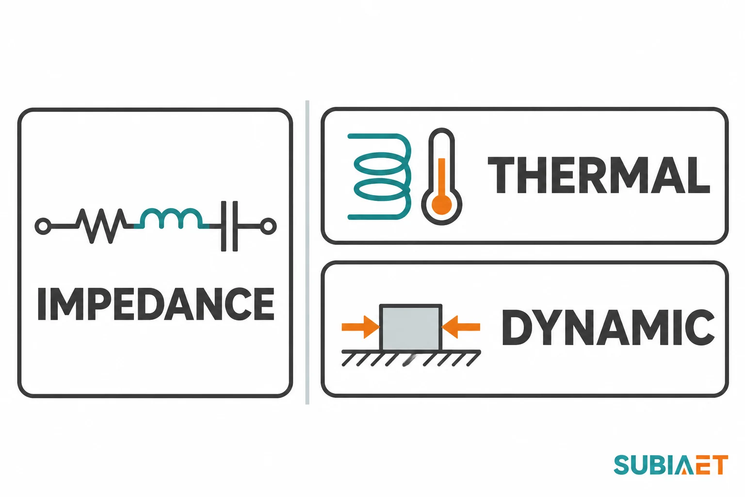
These are entirely different things, and measuring one does not demonstrate the other. IEC 60076-5:2006 addresses the effects of external short circuits. Its published scope describes calculation procedures for thermal withstand and a special test and theoretical evaluation methods for the relevant dynamic effects. An impedance measurement, however precise, is not a short-circuit withstand demonstration.
The withstand capability of a transformer depends on the mechanical design of the winding: the conductor geometry and cross-section, the arrangement of turns and discs, the support structure between windings, the axial and radial clamping, and the structural integrity of the coil-and-core assembly as a whole. Two designs with the same impedance can use different conductor cross-sections, forms, materials and support arrangements. Neither material is inherently superior; what matters is whether the specific offered design has been shown to withstand the agreed fault duty.
The evidence to request from each supplier is:
Horizon Power’s specification lists short-circuit testing as a purchaser-selectable special test, separate from the routine test program. That is a purchaser-specific test provision. The IEC scope also describes a theoretical evaluation method for dynamic effects, and the contract determines what evidence the buyer accepts. The key point for a buyer comparing two offers is that an impedance declaration does not substitute for withstand evidence, regardless of which conductor material is used.
The winding conductor material affects several distinct interfaces that must each be evaluated separately.
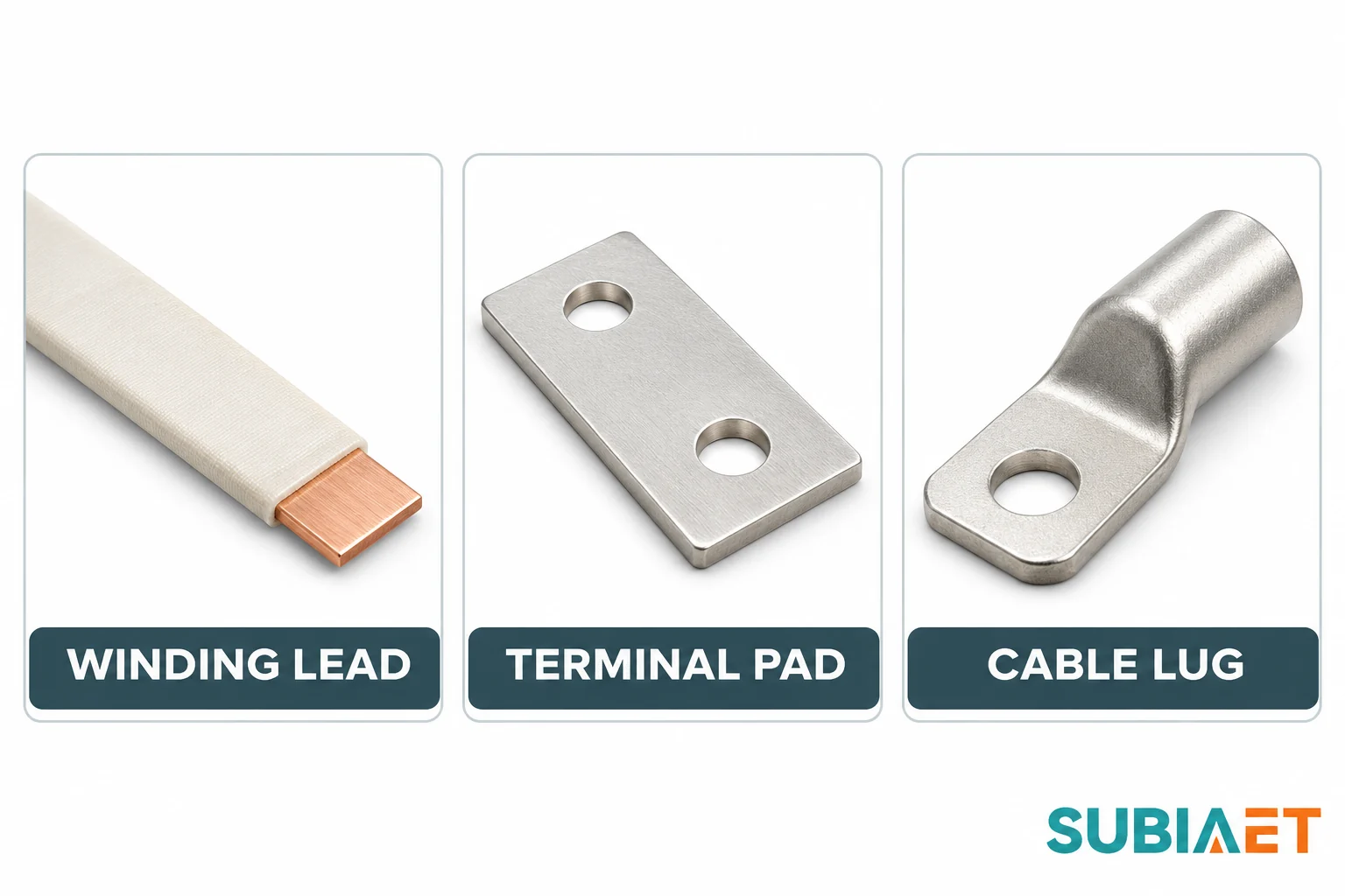
Inside the transformer, the coil conductors are wound from either copper or aluminum strip, wire, or foil. The leads that connect the coil to the bushings may use the same material as the coil or may transition to a different material through a factory-made joint. Verify the offered joint design for either winding material. Where an aluminum-to-copper transition is present, identify its location and the manufacturer’s design for maintaining electrical contact and mechanical integrity. HPS’s technical note specifically describes the oxide behavior of aluminum at connections and the need for designs that protect contact integrity. The nature and location of internal material transitions should be declared by the supplier and form part of the technical documentation.
At the bushing or terminal pad, the transformer presents an external connection surface. The pad material, bolt pattern, pad size, and current rating of the pad must match the cable or busbar being connected on the site side. The winding and the external terminal pad can use different materials. Obtain the actual pad material from the offered drawing or data sheet.
On the site side, cables and busbars introduce another material interface. If the buyer is connecting copper cables with copper lugs to the transformer’s terminals, and the terminal pad is aluminum, that transition requires documented connector approval and installation method. The connector must be rated for the current, the pad geometry, and the specific materials. This is not a field improvisation; it requires manufacturer documentation.
For procurement, verify each of the following from both offers:
Eaton’s note on copper versus aluminum conductor designs distinguishes internal liquid-immersed connections from exposed external interfaces, reinforcing that these are separate design and documentation questions.
The following table applies the approach above to a fictional procurement scenario. A buyer requests a three-phase 1,000 kVA, 11/0.4 kV line-to-line, Dyn11, 50 Hz, sealed liquid-immersed ONAN distribution transformer. Both offers use the same principal tap, insulation and impedance requirements, cable routes, load waveform, cooling, site ambient and altitude, agreed network fault duty, and test basis. Either conductor material is permitted, and both HV and LV material must be disclosed. The values are entirely fictional and are used only to show what can and cannot be decided from a typical first-round submission.
| Item | Common basis | Offer A | Offer B | Decision |
|---|---|---|---|---|
| HV and LV winding conductors | Material must be declared for each winding; the technical performance requirements are the same. | Copper HV and copper LV. | Aluminum HV and aluminum LV. | Both material declarations are acceptable under this fictional tender. Check the complete designs. |
| No-load loss | Guaranteed value at the specified excitation voltage, 50 Hz, common tap and test connection. | 0.90 kW guaranteed. | 0.85 kW guaranteed. | B has the lower comparable stated no-load guarantee. This does not establish overall efficiency. |
| Load loss | Guaranteed at rated current, 50 Hz, same HV–LV pair and tap, referred to the stipulated 75 °C contract reference basis. | 8.1 kW guaranteed on the requested basis. | 7.6 kW listed as a raw measured figure without a reported reference temperature or guarantee status matching the request. | Keep the comparison open. Request a corrected, guaranteed value on the common basis. Do not apply an I²R-only correction to total loss. |
| Temperature rise and cooling | Project winding and applicable liquid temperature rise requirements at rated ONAN duty under the agreed conditions. | Applicable design evidence and guarantees identified for the offered cooling arrangement. | Same ONAN label and a guarantee offered; evidence cites another configuration without applicability explanation. | Ask B to reconcile the design record, variant and duty. A cooling code does not itself demonstrate temperature rise. |
| Installation and weight | Same project plan and clearances, quoted fittings included, weights both on filled operating basis. | 1,700 × 1,120 × 1,600 mm; 2,850 kg filled. | 1,760 × 1,190 × 1,650 mm; 2,680 kg filled. | Both dimensioned offers fit the fictional room on the stated basis. B is wider and lighter in these offered configurations only. Verify separate shipping and handling data. |
| Impedance and short-circuit withstand | Same specified impedance basis, network duty and contract-defined thermal and dynamic evidence. | Impedance declaration and a design/reference evidence applicability statement provided. | Impedance declaration only; short-circuit withstand evidence not supplied. | B is open on withstand despite the common impedance requirement. Request evidence tied to the offered active part and agreed fault duty. |
| Winding lead and site cable interface | Same buyer copper cable/lug arrangement, terminal pad, phase/neutral design and accessible clearances. | Actual pad and cable/lug interface documented in the offered drawings. | External pad listed but no matched lug/geometry confirmation or statement about applicable internal aluminum-to-terminal transition. | Ask B for the matched interface and internal transition design evidence as applicable. Winding metal does not establish which external cable is acceptable. |
| Commercial comparison | Like scope only; fictional normalized bid price index, no actual quote or market price. | 100 price-index units. | 94 price-index units, with technical gaps still open. | B is lower on stated initial price and the comparable no-load guarantee. Neither settles total loss, actual installation suitability or awarded cost while the open evidence remains. |
Summary disposition: Offer A is the currently more complete technical submission, conditional on final drawing and evidence approval and the delivered serial-number routine test confirmation. Offer B should be kept open pending: a corrected load-loss figure with declared reference temperature and guarantee status on the common basis; reconciliation of the temperature-rise evidence with the offered cooling configuration and site conditions; short-circuit withstand evidence tied to the offered active part and agreed fault duty; and documentation of the cable-to-pad interface and internal transition design. The supplier provides the corrected guarantee and supporting documents. The buyer’s electrical engineer checks the thermal and fault evidence, and the site installation team confirms the terminal and handling fit against the approved drawings. Procurement then recompares the technically responsive offers using the project’s commercial weighting or full lifecycle cost analysis.
The 75 °C loss reference used in this example is a stipulated contract comparison condition. It is not the same thing as the winding temperature rise of either transformer, and no conclusion about winding operating temperature follows from using it as a loss reference.
Neither this table nor the section above establishes a general winner for copper or aluminum as a winding material. The conditional disposition follows from the comparable guarantees and the evidence gaps in these two submissions.
For the lifecycle cost calculation once both bids are on a common loss basis, refer to Transformer Losses and Total Cost of Ownership: Comparing Two Quotations. For interpreting the routine test report delivered with the actual unit, see How to Read a Transformer Routine Test Report Before Shipment. Equipment context for oil-immersed and dry-type distribution transformers is available at Oil-immersed Transformers and Dry-type Transformers.
Not by itself, and not in any universal sense. As the Eaton three-configuration example illustrates, all-copper, all-aluminum, and mixed-conductor designs for the same rated duty can produce essentially the same efficiency at a given load point even though their no-load losses, load losses, and dimensions differ. Efficiency at a specific load point is a result of the complete transformer design—core material and geometry, winding configuration, insulation, and cooling—not of conductor material alone. The only valid comparison is between guaranteed loss figures on a common test basis for the specific units being offered, evaluated at the load profile expected in service.
Only if the correction is applied correctly and the underlying test information is available. Load loss contains two components that correct differently with temperature: the winding ohmic (I²R) component, which scales with the resistance-temperature relationship of the conductor material, and the stray loss component, which typically decreases with increasing temperature. The cited U.S. DOE method illustrates separate corrections and material-dependent winding resistance terms. The project’s governing test method and reference conditions control the actual comparison. Applying a single overall I²R scaling to a total load-loss figure will give the wrong answer. For the comparison to proceed correctly, the supplier should provide the corrected and guaranteed figure on the stipulated common basis; the buyer should not be expected to reconstruct that correction from a raw measured number without the full test record.
Equal declared impedance on a common basis supplies one input to the fault-current calculation. The source network, fault type and configuration also matter. Separately, the transformer’s thermal and mechanical withstand depends on its conductor dimensions, coil geometry, support and clamping. Under the applicable contract, check the thermal calculation and dynamic special-test or theoretical-evaluation evidence for the actual design and fault duty.
No. The terminal pad material, bolt pattern, and current rating must match the cable connector being used. Where the pad is aluminum and the cable lug is copper—or vice versa—the connection requires a specifically approved connector rated for that material combination at the current and pad geometry involved. Using an unapproved connector at a dissimilar-metal joint risks a connection that corrodes, overheats, or mechanically fails over time. The transformer manufacturer’s connection documentation should specify which connectors are approved for each terminal configuration. Confirm the approved external interface on the offered drawings regardless of the winding material.
The pre-award evaluation considers the offered design, drawings and guarantees. Request the routine report for the actual serial number before dispatch or acceptance, as agreed. Check the documented winding resistance, no-load loss, load loss and impedance at the stated test conditions against the guarantees and acceptance criteria that apply. Resolve discrepancies before accepting the unit. The routine report ties these measurements to the delivered hardware.
