Request a Quote
Share the equipment and project requirements. If you need help selecting a model, describe the application.
Have drawings or specifications? Email [email protected] with your project reference.

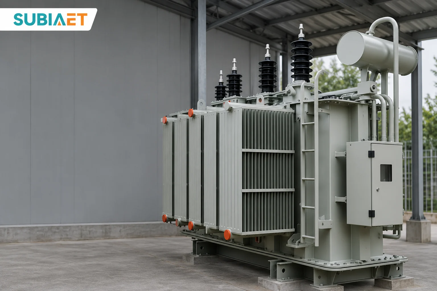
The choice between an on-load tap changer and a de-energized tap changer starts with two facts about the site. First: how far does the supply voltage actually move, and for how long? Second: is there a window in which the transformer can be taken out of service to change a tap? The answer has to account for the load voltage as well as the supply voltage: a stable incoming supply alone does not prove that every operating case is acceptable.
If the incoming voltage sits at a steady, offset level, a fixed tap set during a planned outage may keep the load within its required voltage band. If the incoming voltage swings repeatedly across a band that a single ratio cannot cover, and outages cannot accommodate changes, an on-load tap changer or upstream regulation becomes a candidate. Tap ranges, step sizes, controllers and sensing points then decide whether that candidate can meet the actual duty. The sections below work through the mechanism, the arithmetic and the specification.
A tap changes how many turns of a transformer winding are in circuit. That changes the ratio of primary to secondary voltage. The tapped winding can be on either side, depending on the design. The tap schedule identifies the winding and the ratio at each position.
An on-load tap changer (OLTC) makes the change while the transformer carries load. Because the tap being left and the tap being entered are at different potentials, the transition has to be managed: a transition resistor or reactor limits the circulating current while the changer bridges between positions, allowing transfer without a service interruption for normal changes. Reinhausen explains the switching principle. The tapped winding may sit on either side depending on the design; the tap schedule identifies where the change is made.
A de-energized tap changer (DETC), also called an off-circuit tap changer, changes the ratio only under the de-energized conditions specified for the equipment. De-energized is not the same as unloaded. A transformer connected to the supply with its secondary breaker open is still energized: the primary winding remains at voltage and the core is excited. The DEETAP SPTM manual requires de-energization on both the high- and low-voltage sides and describes manual and motor drives. Confirm the switching condition and permitted positions from the particular unit documentation.
Drive type is a separate question. A de-energized tap changer may be fitted with a motor drive or worked by hand. A motor box on the tank, a side cabinet, a handwheel, or a control pushbutton therefore tells you nothing about whether the switch is an OLTC or a DETC. Identification comes from the nameplate, the tap table, the connection diagram and the manufacturer’s documentation. That matters at the procurement stage, because a specification that says “motor-operated tap changer” has not yet said which of the two families is being bought.
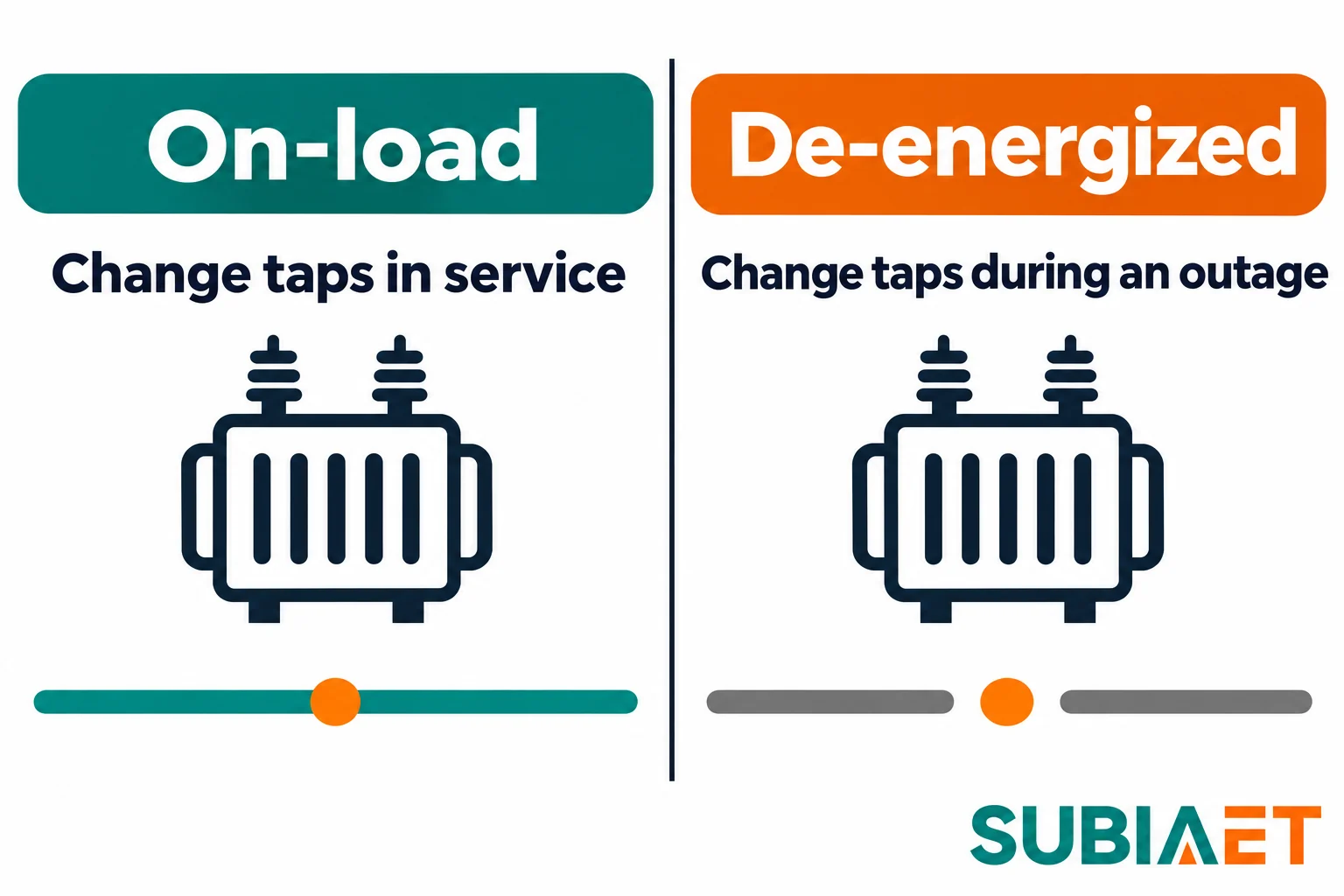
One more distinction belongs here rather than later. An OLTC changes the ratio; it does not by itself guarantee a particular busbar voltage. Whether the regulated point lands inside its band depends on the step size, the range available, and where the controller is measuring — a point developed in the next two sections.
The fastest way to decide whether a fixed tap is enough is to run the site’s voltage envelope through the tap table. Take a deliberately simple, hypothetical three-phase case: a transformer rated 11 kV / 400 V, with three available input tap ratings — 10.725 kV, 11.000 kV and 11.275 kV.
Each of those numbers means something specific: the tap identifies the input voltage at which the transformer delivers its rated secondary voltage, in this case 400 V, with that tap selected and no load connected. So the ideal no-load output for any tap and any actual input is:
V_out ≈ 400 V × (actual input voltage) ÷ (rated input voltage of the selected tap)
That is an ideal approximation at nominal frequency. It ignores impedance drop, excitation current and manufacturing tolerance, and it is only a first screen. Schneider Electric’s voltage tap example illustrates the same ratio principle on a different transformer. The selected primary tap rating is the input that corresponds to the rated secondary voltage; it is not a command to add that many volts to the secondary.
Case 1 — a steady offset. Suppose the measured supply sits consistently near 10.725 kV. Select the 10.725 kV tap during a permitted planned outage, and the ideal no-load output becomes 400 × 10.725 / 10.725 = 400 V. The real check is whether the loaded busbar remains inside the acceptance band over the expected load and power-factor range. If it does, and the supply profile supports that assumption, the fixed setting is a candidate. Its drive, inspection needs and any later outage for adjustment still belong in the equipment and operating plan.
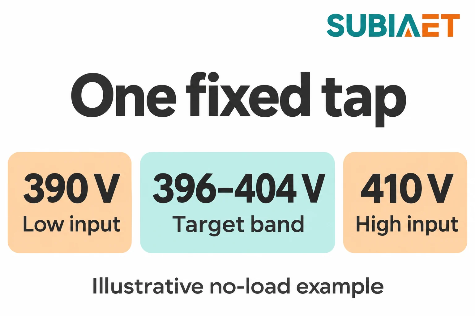
Case 2 — a moving envelope. Now suppose the same site’s supply varies between 10.725 kV and 11.275 kV over the working week. Keep the transformer on its nominal 11.000 kV tap. At the low end of the envelope the ideal output is 400 × 10.725 / 11.000 = 390 V; at the high end it is 400 × 11.275 / 11.000 = 410 V. Against an example acceptance band of 396–404 V at the utilisation point, both ends are outside.
Why another fixed position does not solve this example. A constant ratio scales both input voltages by the same factor. The ratio of high to low input is 11.275 / 10.725, about 1.051, while the allowed output band can accommodate only 404 / 396, about 1.020. A different fixed ratio therefore cannot fit both extremes. On the 10.725 kV tap the ideal outputs are about 400–420.5 V; on the 11.275 kV tap they are about 380.5–400 V. The absolute widths differ with the selected ratio, but neither interval fits within 396–404 V.
Matching the ratio to the input works at the points where the two coincide. With the input at exactly 10.725 kV and the 10.725 kV tap selected, the ideal output is 400 V. With the input at exactly 11.275 kV and the 11.275 kV tap selected, it is again 400 V. In between, the output is whatever the selected tap produces. A fixed tap is therefore suited to a persistent offset only when the full operating envelope fits the allowed band; it cannot follow a moving envelope by itself.
Four further checks keep this first screen tied to the operating conditions.
Loaded voltage. The ideal calculation assumes no current. In service, winding resistance, leakage reactance, current magnitude and power factor affect the difference between the internal induced voltage and the terminal voltage. Include the connecting cable or busbar when calculating voltage at the utilization point. Do not assign a universal drop from the percentage impedance alone, or assume that every power-flow case lowers the voltage. The same tap can produce acceptable voltage at one load level and fall outside the required band at another; evaluate the relevant load and generation cases.
Source frequency. The turns ratio itself is essentially frequency-independent, but the excitation and reactive impedance are not. State the nominal frequency and any relevant operating variation. Confirm that the proposed voltage and frequency combinations stay within the transformer’s permitted excitation and thermal conditions. A tap decision based only on nominal voltage cannot establish suitability for an abnormal frequency condition; the manufacturer’s ratings and the project operating envelope remain separate checks.
Range and step. A tap changer with a range that covers the envelope may still miss the band between its available positions. At 10.8625 kV, halfway between the first two primary tap ratings, the two nearest taps give about 405.1 V and 395 V in this example. Neither falls inside 396–404 V. The available range covers the extreme input values, but the steps are too coarse at that intermediate voltage. Check every relevant operating interval, not just the two endpoints. A control delay cannot create a missing ratio, and the acceptable load-voltage band is not automatically the controller’s deadband.
Fast excursions. Assess brief voltage sags separately using their depth, duration and the connected load’s ride-through requirement. An OLTC regulation scheme typically addresses sustained voltage deviations and may include deliberate delays and mechanical movement. Its actual response depends on the selected equipment and controls. Do not assume that buying an OLTC resolves a transient-voltage requirement; establish what the load must ride through and compare that need with the regulation scheme’s documented response.
Once a moving envelope has been established, two documents decide whether the hardware will actually deliver: the tap schedule and the control scheme.
The schedule is the table that defines each position. Read it in this order.
Which winding is tapped. High-voltage taps and low-voltage taps are not interchangeable. The tapped winding sets where the changer physically sits, what current it must carry, and what insulation it must withstand. A percentage range quoted without naming the winding is incomplete.
The reference base for the percentages. Tap ranges expressed in percent are referred to the rated voltage of the tapped winding. This matters when someone tries to convert the percentage directly into volts at the terminals of the other side: the increments are physical turns on one winding, and their effect at the secondary depends on the ratio at which the transformer is operating, not on the nominal ratio alone.
Range and step. A documented historical example makes the arithmetic concrete. Western Power Distribution’s EE SPEC 4/7, issued in May 2015, specified full-power positions and ±8 × 1.25% on the high-voltage winding. That is ±10%, with 16 increments between the end positions. It also defined a position-numbering direction, end limits and remote-control responsibility. This is an example of what a buyer can define for a project, not a current universal specification or a claim about a supplier’s standard offering. Obtain the offered position-to-voltage schedule rather than inferring it from the percentage range alone.
Permitted positions and limits at each position. The requirement for full-power positions in that historical specification identifies a rating that buyers should make explicit. A percentage range alone does not confirm the current or power available at every position. Where the transformer has to carry the required load at the end positions, state that duty and have the ratings across the tap range confirmed position by position. The schedule should show any limits, so a nominally sufficient range is not accepted without checking that the load can actually be carried there.
Direction and physical labelling. Does a higher tap number raise or lower the secondary voltage? Do not assume a universal convention. Read the manufacturer’s position-to-ratio schedule, nameplate and dial marking together, and define what each control command is intended to do. Ratio verification at the specified positions should agree with that correspondence. A controller configured to the opposite direction could respond to a voltage error by increasing it, so the drawing and command definitions matter as much as the available number of steps.
End limits. Define the permitted end positions, movement limits and the signals needed by the controller and operator. Operation at a limit means no further correction is available in that direction. Position feedback, limit indication and an out-of-band alarm answer different questions: where the mechanism is, whether another step is permitted, and whether the voltage requirement is being met. Specify the required functions instead of assuming that the presence of one signal supplies the others.
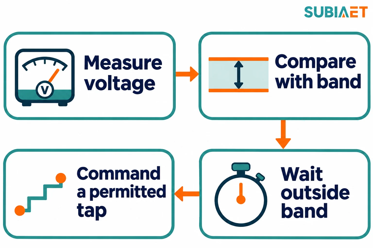
An automatic on-load scheme is a loop, not a device. The control unit measures voltage at a defined sensing point, compares it with a reference, and commands a tap movement when the deviation exceeds the configured bandwidth for the specified delay. Written out:
The loop then assesses the resulting voltage according to the controller’s configured timing. Reinhausen’s ECOTAP VPD manual, §4.2 describes measurement, bandwidth and delay for one control package. Delay can avoid responding to deviations that clear before action is required, but it does not by itself solve a step-size mismatch. Review the selected controller’s behavior, limits and coordination with other voltage-control devices.
The four-stage logic is where the distinction between an OLTC and a controller becomes practical. The tap changer is a mechanism — contacts, transition impedance, motor drive. The controller is a measuring and decision function. They are distinct in the equipment package: some packages integrate a controller with the motor drive, others supply the drive with a separate panel, and not every OLTC comes with automatic control at all. Where automatic regulation is required, a specification for “an OLTC” must also define the controller, sensing point and supply boundary. The mechanism alone does not define the complete automatic scheme.
Three further points belong to the control scope rather than the tap changer.
Sensing point. Measuring at the transformer terminals is not the same as measuring at the board that has to stay in band. The intervening cable or busbar changes the voltage relationship as load and power factor change. Define the project’s acceptable voltage at the load and the controller’s target and deadband at its sensing point separately. Name those points on the drawing, then evaluate the relevant demand and generation cases. A controller may hold its measured voltage within its own band while the downstream utilization point still fails the project requirement.
Position feedback and interfaces. Define the position indication, command inputs, movement limits and alarm outputs separately. A position transducer reports the tap position; raise and lower commands request movement; an alarm identifies a specified condition. State the required signal types and communications interface, and assign responsibility for matching them to the plant controls. The alarm list may include out-of-band voltage, a tap limit or a changer fault, according to the project and equipment. Confirm which functions are supplied and how they will be checked.
Manual, automatic and remote scope. Local manual electrical operation, local automatic, and remote control from a SCADA system are three different capabilities, and a scheme may have any combination. The historical example above separated remote control responsibility from the tap changer supply, which is a useful reminder that “remote control” is an integration deliverable, not a feature of the mechanism.
A tap range alone leaves the voltage problem and several supply interfaces undefined. Send the voltage and load data together so the supplier can assess each operating case on the same basis. The following table turns those conditions into quotation inputs and purchase-document checks. Where a value is provisional, identify who will confirm it and when; otherwise suppliers may quote against different assumptions without making that difference visible.
| Input | What to state | Why it changes the answer |
|---|---|---|
| Supply voltage envelope | Minimum, normal and maximum input, with how long each level lasts and how often it recurs; source of the data | Helps establish the required range and whether one fixed setting is sufficient |
| Load envelope | Maximum and minimum demand, power factor at each, and the dominant load type | Determines the loaded drop, which sets the actual busbar voltage |
| Generation or export cases | Whether embedded generation can raise the busbar, and at what output | A reverse-power or high-voltage case can be the binding constraint |
| Regulated point and band | The exact point where voltage must be held, its permitted band, and the separate controller sensing point and settings | Connects the load requirement to the control design without equating the two bands |
| Outage allowance | How many shutdowns are available, how long, and in which windows — or that none are | Decides whether a DETC can be re-tapped at all |
| Frequency | Nominal and expected variation, where relevant | Affects reactive drop and excitation, and the loss picture |
| Tap schedule | Tapped winding, range, step, number of positions, numbering direction, full or reduced power at each position, current and voltage limits | Prevents a quotation that is technically valid but unusable |
| Ratings across taps | Confirmation that the transformer carries the required load at the extreme positions in this application | Establishes the applicable power and current limits at those positions |
| Control scope and responsibility | Who supplies the controller, whether it is integrated with the drive or separate, the sensing inputs, the position output, the alarm contacts, the communications protocol, and the local/remote split | The controller is a separate function from the mechanism |
| Coordination | Any upstream regulating device, and whether parallel transformers share the duty; if so, how tap positions are coordinated | Ratio differences can drive circulating current between parallel units |
| Tests and evidence | Ratio measurement at every position, control function test, and the manufacturer’s documented maintenance and service plan for the tap changer | Checks that the delivered equipment matches the schedule and the control logic |
| Documentation | Nameplate data, tap table, connection diagram, control scheme drawing | The basis for commissioning and for later operation |
Two entries in that table deserve emphasis.
Parallel operation. Where two transformers run in parallel, a difference in their secondary induced voltages can drive circulating current between them, independently of the external load. A mismatch may arise from different ratios or from control schemes that move units without suitable coordination. Matching tap position numbers alone does not prove matching ratios. State the parallel arrangement and ask how ratio compatibility and regulation will be handled across its operating cases. This is a system decision to resolve with the transformer and control requirements, rather than leaving each unit’s tap schedule to be considered in isolation.
Maintenance and acceptance evidence. Request the manufacturer’s inspection requirements, service intervals, contact-wear criteria where applicable, and replacement-parts plan. The equipment design and operating duty determine what service is needed; do not assume one maintenance regime for every OLTC or that a DETC has no inspection requirements. Include any relevant oil-compartment work and the required outages in the comparison. Agree how the ratio at the specified positions and the control functions will be verified, including the configured delay behavior, permitted movement and limit blocking. Assign who performs and accepts each check, so the purchase documents connect the rated schedule with the equipment and controls delivered.
This article deliberately stops at requirements. Isolation, switching and tap-changing procedures belong to the manufacturer’s operating instructions and the site’s own safety rules, and a specification document is the wrong place to reproduce them.
To move from these considerations to a quotation, assemble the table above into a single document with the voltage envelope drawn as a graph against time, the load profile on the same time axis, and the outage windows marked. Then state explicitly which of the two families is preferred and why — persistent offset, moving envelope, or no switching window — and ask the supplier to confirm the tap schedule position by position alongside the loaded voltage at the regulated point.
The transformer nameplate guide explains how to read a tap schedule. The transformer impedance guide covers loaded voltage drop. See the SUBIA power transformer family for the related equipment range.
The transformer must be de-energized as required by the equipment documentation. With the secondary load disconnected, the primary can still energize the transformer.
A motor can drive either type. Check the manufacturer’s designation and the electrical conditions specified for changing taps.
An OLTC regulation scheme typically addresses sustained voltage deviations. Assess short sags separately using their depth, duration and the connected load’s ride-through requirement.
The range determines the available span of ratios. Check the discrete steps, the loaded voltage at the point that matters and the control scheme to see whether the project can stay within its band.
