Request a Quote
Share the equipment and project requirements. If you need help selecting a model, describe the application.
Have drawings or specifications? Email [email protected] with your project reference.

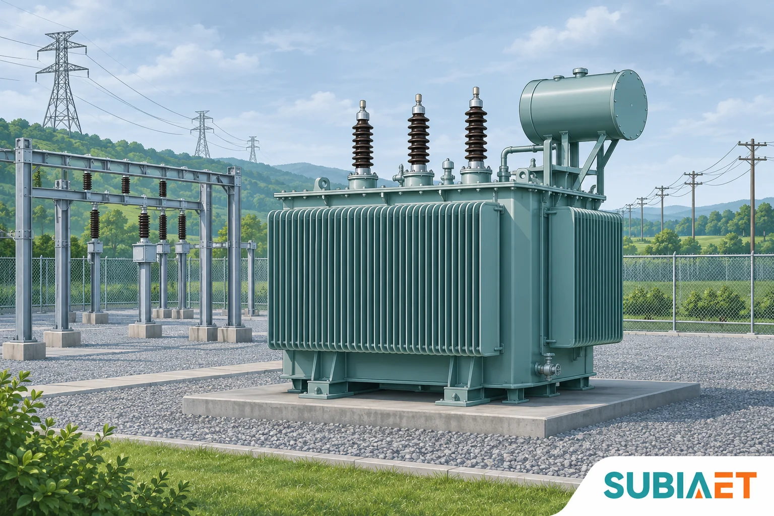
An electrical transformer is a static electromagnetic device that transfers electrical energy between AC circuits, changing voltage or keeping it approximately the same. The conversion requires no rotating shaft and creates no energy. In the common two-winding power transformer followed here, an alternating source energizes the primary, changing magnetic flux links the windings through the core, and voltage is induced in the secondary. The windings are electrically insulated from each other, so energy transfers without an intentional conductive connection between the circuits.
Three conditions govern the common power-frequency example: the supply must be alternating (or at least changing), the frequency must suit the design, and the windings must share a magnetic path. Change any of those and the clean voltage ratio described in textbooks stops describing what you will measure at the terminals.
In a power system, the transformer is the voltage handoff point. A conventional AC route runs from a generator, through a generator step-up transformer to a high-voltage transmission line, then through substation transformers that step down to a distribution voltage, and finally through a distribution transformer close to the load, which brings the voltage down to what a facility actually uses. Real grids vary this chain — generation and distribution can connect at different voltage levels, and high-voltage direct-current links use converters together with transformer equipment at their AC interfaces — but the handoff role is the same wherever it appears.
The U.S. Department of Energy explains the role of AC voltage transformation in transmission.
The reason to make that handoff at high voltage is arithmetic rather than preference. For fixed transferred real power, power factor and circuit configuration, raising voltage lowers current proportionally. The appropriate single-phase or three-phase power relationship gives that current change. Conductor losses follow the square of current, so at the same transferred power and comparable conductor conditions, ten times the voltage means one tenth the current and one hundredth the resistive loss in the line. That is why long-distance transmission runs at voltages far above normal final-circuit utilization voltages, and why the transformer — a device that changes voltage while keeping frequency — sits at both ends of the line.
It is worth being precise about what “fixed transferred power” assumes. The loss advantage holds when you compare two designs moving the same power, not when you compare a lightly loaded high-voltage line against a heavily loaded low-voltage one. Conductor cross-section, distance, load factor and power factor all move the comparison. The transformer itself does not create the saving; it makes the high-voltage operating point practical.
Strip away the tank, bushings and cooling hardware and you find three things: a magnetic core, a winding connected to the source, and a winding connected to the load. The winding that receives power is usually called the primary, and the winding that delivers it is the secondary. In most power-frequency designs the windings are insulated copper or aluminium conductors wound around a laminated magnetic core — thin steel sheets stacked and insulated from one another so that circulating eddy currents inside the steel are kept small.
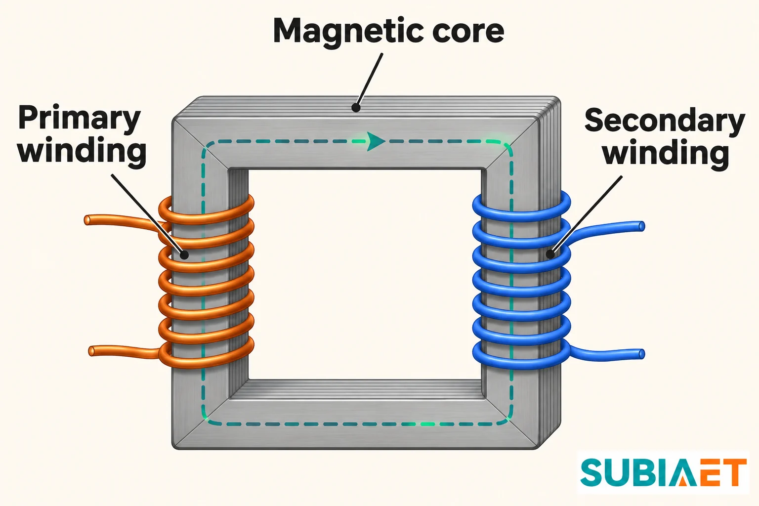
When alternating voltage is applied to the primary, excitation current establishes changing magnetic flux. The magnetic core gives the flux a low-reluctance path, so much of it links both windings. Some leakage flux does not link both windings and contributes to the real transformer’s internal reactance. Because the applied voltage is alternating, the flux is continuously rising, falling and reversing. A winding sitting in a changing flux has a voltage induced across it, and the magnitude depends on how many turns it has: each turn sees roughly the same induced voltage, so more turns in series add up to more volts.
That is mutual induction, and it explains the arrangement. In the separate-winding design, there is no intentional conductive connection from primary to secondary. Their shared changing flux allows power transfer while preserving that winding separation. Whether the complete installation meets a particular isolation requirement also depends on its insulation and connections.
The important subtlety is what happens with nothing connected to the secondary. The secondary still has a voltage across its terminals — the flux is changing whether or not current flows. But with an open circuit there is no secondary current, so no power is delivered. The primary, meanwhile, draws a small current even with no load: a real transformer needs magnetizing current to establish the core flux, plus a bit more to cover hysteresis and eddy-current losses in the core. That excitation current is normally smaller than full-load current in the intended operating range, but core losses still generate heat. No-load operation is not a guarantee of a cold enclosure or a substitute for checking the specified voltage, frequency and cooling conditions.
Eaton’s transformer fundamentals illustrates the core, windings and voltage ratio.
When a connected load completes the secondary circuit, the induced voltage drives current through it. That current has its own magnetic effect. By Lenz’s law, it opposes the change producing it; the source and primary winding respond to this secondary ampere-turn demand.
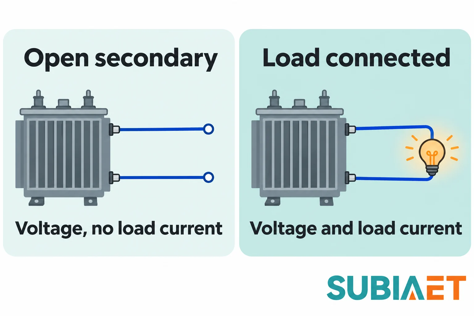
The applied primary voltage is balanced largely by the voltage induced from the changing core flux, with allowance for winding resistance and leakage effects. At fixed voltage and frequency, connecting the load causes the source to supply additional primary current. The magnetomotive force of that load-current component largely balances the secondary’s effect. The main flux therefore remains close to its no-load value in normal operation, while the source supplies more energy.
This is the key mental model: at a fixed applied voltage and frequency, the core flux stays roughly constant from no load to full load. What changes is the primary current. The transformer does not “build up” power internally — the additional energy delivered to the load is drawn from the source through the primary, minus the losses. Input real power equals output real power plus losses in steady operation.
That balance also explains the current step in the opposite direction from the voltage step. If the secondary delivers more current at lower voltage, the primary must carry less current at higher voltage, and the apparent-power products are equal in the ideal model. A real transformer also draws excitation current and loss power.
For a two-winding transformer, the voltage ratio follows the turns ratio. Written in the orientation that avoids the most common mistake:
V_secondary / V_primary ≈ N_secondary / N_primary
Secondary turns on top, secondary voltage on top. If the secondary has fewer turns than the primary, the secondary voltage is lower and the transformer is step-down. If it has more, the transformer is step-up. If the two windings have the same number of turns, the voltage is roughly unchanged and a separate-winding transformer can provide circuit separation without a significant voltage change.
Work the numbers with an ideal single-phase example. Take a primary-to-secondary turns ratio of 4:1 and apply 480 V rms at a fixed AC frequency. The secondary produces 120 V rms. Connect a resistive load that draws 10 A at 120 V:
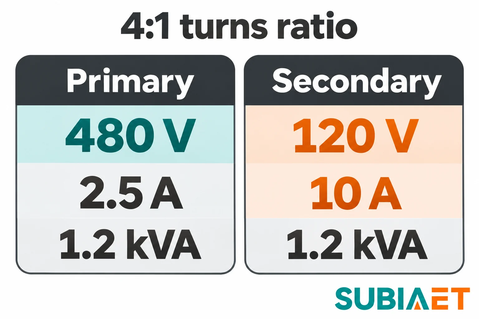
So voltage steps down by four, current steps up by four, and the power product is 1.2 kVA on both sides once magnetizing current and losses are neglected. The fundamental frequency does not change: a 60 Hz supply gives a 60 Hz fundamental secondary voltage because both winding voltages follow the same changing core flux. Real waveform distortion does not make the unit a frequency converter. Nothing in the mechanism divides or multiplies cycles.
Two further points about direction. In a step-up transformer the secondary voltage is higher than the primary and the secondary current lower; a step-down transformer does the reverse; an equal-turns separate-winding transformer has an ideal voltage ratio of one and equal ideal load-current magnitudes. Excitation current and losses still affect the actual primary input. In the supply-to-load example, average real power enters the primary and leaves the secondary, while the AC currents reverse during each cycle. Polarity marks or connection diagrams identify the relative winding polarities, which matter for intended interconnections, parallel operation and three-phase arrangements.
OpenStax derives the ideal voltage and current ratios.
The ideal model is a teaching tool, not a specification. Five practical differences separate it from a real unit.
Losses become heat. Winding resistance produces resistive loss, often called copper loss even when another conductor material is used. At fixed resistance, that term rises with the square of winding current. Core losses — hysteresis from repeatedly reversing the magnetization, and eddy currents in the steel — stay roughly constant at fixed voltage and frequency and are present even at no load. Both appear as heat that must leave the enclosure.
Internal impedance changes the loaded voltage. Windings have resistance, and not all flux links both windings perfectly; the leakage component behaves like a series reactance. The terminal-voltage change depends on load current and power factor: it commonly falls under a lagging load and can rise under some leading loads. The turns ratio gives an approximate no-load voltage relationship. Loaded voltage, regulation and tap settings are a separate conversation.
Construction determines how heat gets out and how the unit is insulated. Liquid-filled designs immerse the core and windings in insulating oil that circulates by convection, carrying heat to the tank walls, fins or radiators; the oil does double duty as dielectric and coolant. Dry-type designs use non-liquid insulation — cast resin or impregnated systems — and ultimately reject heat to surrounding air, by ventilation, enclosure surfaces or assisted airflow according to the design. Dry-type does not necessarily mean an open-ventilated enclosure.
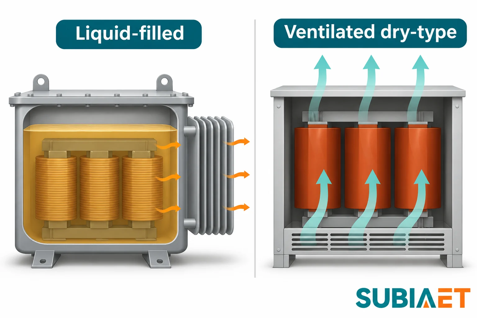
The tradeoff is practical. A liquid-filled design uses the liquid as both dielectric and heat-transfer medium, so fluid choice, sealing, containment and applicable fire provisions enter the installation decision. A dry-type design avoids a transformer insulating liquid, but still needs suitable heat rejection and environmental protection. Either construction must suit the specified ambient temperature, altitude, enclosure and cooling conditions; neither label alone establishes efficiency, maintenance needs or suitability for a harsh environment.
Winding arrangement determines isolation. Two separate windings provide galvanic isolation: the secondary circuit has no conductive path to the primary. An autotransformer instead uses one tapped winding, so part of the winding is common to both sides. For suitable applications and voltage ratios, sharing part of the winding can reduce material compared with a separate-winding design, but it does not provide galvanic isolation. Its conductive connection must be accounted for in protection, earthing and the intended use. Separate windings versus a shared winding is a design decision with safety consequences, not a labelling detail.
Steady DC produces no sustained induction. After the transient from a DC connection, a steady winding current would produce steady flux. With no continuing change in flux, there is no sustained induced secondary voltage. The primary also loses the back-emf that normally limits current, so it behaves like a low-resistance coil and can draw damaging current limited mainly by winding and source resistance after the transient. Power electronics can create a changing waveform so a transformer can participate in a DC conversion system; connecting a conventional AC winding directly to a steady DC source is a different and unsuitable duty.
Once the mechanism is clear, selection becomes a matter of matching conditions rather than remembering formulas. Six inputs do most of the work: the AC voltage available at the supply point, the voltage the load actually needs, the system frequency the unit is designed for, the number of phases, the apparent power the load requires including realistic spare capacity, and the installation environment — indoor or outdoor, ambient temperature, altitude, ventilation, humidity, dust, corrosive atmosphere and fire requirements.
Consider a conditional example. An indoor workshop is fed at 11 kV and needs 400 V three-phase for motors and drives, with a measured demand near 800 kVA and modest planned growth. The team could evaluate a dry-type cast-resin unit with suitable ventilation and clearance for the indoor, fire-sensitive location, while comparing any liquid-filled proposal against the applicable fluid, fire and containment requirements. If the same load instead sat in an open process yard with dust and wide temperature swings, and the layout allowed a compound, an appropriately enclosed liquid-filled design could be another candidate. Its environmental and thermal suitability would still need confirmation for those conditions. Change one condition — indoor siting, or ambient temperature above the design assumption — and the answer can move, which is why the requirement list matters more than the product label.
Two things are worth checking before any of this becomes a purchase conversation. First, the exact model table for the voltage class you are considering, because series pages list families rather than verified specifications and ratings must be read with their conditions and units attached. Second, the total connected load arithmetic, because spare capacity chosen without a load profile or growth plan can result in either unnecessary capacity or an early replacement.
For construction options, the SUBIA transformer range is the general starting point. The oil-immersed transformer series page lists distribution transformers across 6–10 kV, 20 kV and 35 kV classes, and the dry-type transformer series page lists cast-resin units in the same voltage classes alongside amorphous-core designs. If your project is a plant expansion rather than a single unit, the factory expansion load-sizing article works through the demand arithmetic that turns individual machine loads into a transformer rating.
Changing core flux induces voltage even when the secondary circuit is open. A closed path is required for load current. The open terminals can therefore be energized even though the transformer is delivering no load power.
When both windings have the same number of turns, their ideal induced voltages are equal. A 1:1 two-winding transformer can be used to separate circuits while keeping the voltage level. Its actual output still depends on load and the transformer’s internal voltage drop.
In normal power-frequency operation, the secondary voltage repeats at the fundamental frequency of the changing core flux set by the AC supply. A 50 Hz supply gives a 50 Hz fundamental output. Producing a different supply frequency requires equipment designed for frequency conversion.
A change at switch-on can induce a brief secondary voltage. Steady flux cannot sustain it. A conventional AC winding can draw damaging current on a DC supply, so DC-to-AC conversion is needed before a transformer can be used to change the voltage in that system.
A step-up transformer trades higher voltage for lower current at a given transferred power. Some input power is lost as heat in a real unit. The benefit on a transmission line is that less current is needed for the same delivered power, which can reduce resistive losses.
