Request a Quote
Share the equipment and project requirements. If you need help selecting a model, describe the application.
Have drawings or specifications? Email [email protected] with your project reference.

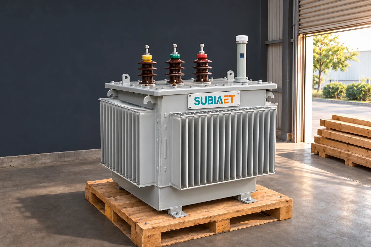
A routine test report is evidence about one serial-numbered transformer, measured under stated conditions, and compared against a criterion that comes from your contract — not from the report itself. Reading it well means passing three gates in order. First, does this document actually describe the unit you are buying? Second, is each result stated with enough conditions that you can interpret it? Third, does the number that belongs on the contract basis meet the agreed limit? A report can fail at any gate, and a report that fails at the first or second gate has not told you anything about acceptance yet, no matter how many rows carry a PASS stamp.
That ordering matters because the three failure types have different remedies. A traceability gap requires investigation of the identity link, followed by the appropriate serial mapping, controlled report or correction of any actual configuration discrepancy. A missing condition is an interpretability problem, solved by a clarification or a corrected row. A value outside the agreed criterion is a performance problem, which needs a formal disposition rather than a reissued PDF. Buyers who collapse all three into “the report is not acceptable” tend to negotiate the wrong remedy, and buyers who collapse them into “the report says PASS” tend to release equipment they cannot later defend.
Start with identity, because everything downstream depends on it. A model designation, a rating, and a green PASS stamp do not establish that the document in front of you belongs to the asset on the skid in the dispatch bay. Transformers of the same family share drawings, loss tables and test sheet templates; the serial number is what separates them.
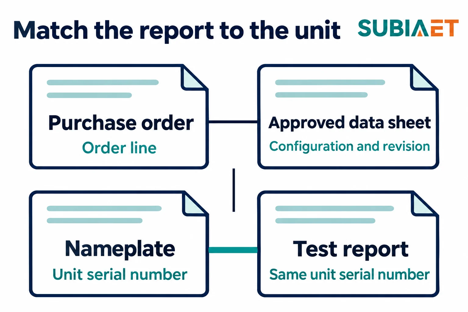
Work the trace in both directions. From the report, take the manufacturer’s serial number and check it against the nameplate on the unit — either the physical plate or, if you are reviewing remotely, an approved nameplate photograph plus the factory serial list for the order. From the purchase side, take the purchase order line and your own equipment tag and trace them to the approved drawing and data-sheet revision that governed manufacture. Then confirm that the tested configuration on the report matches that revision: rating in kVA, HV and LV voltages, number of phases, frequency, vector group, tapping range and the tap position at which each test was run.
Do not expect identical identifiers in every file. A purchase order is usually raised before serial numbers are allocated; a data sheet is approved before the tank is built; your equipment tag may exist only in your own asset register. What you need is a traceable mapping, not matching strings. A buyer-side specification can make this explicit: the Tacoma Power purchase specification requires factory data for each unit, including the serial number and the specified loss and impedance conditions, together with a mapping from manufacturer serial numbers to the buyer’s own equipment identifiers before shipment. That requirement exists precisely because the two numbering systems are separate.
Finally, check the report as a document. Which revision is it, and are all referenced attachments present? Is it dated, and is it signed or otherwise authorized to the extent your contract requires? An unsigned draft and a controlled issue may carry the same values but not the same standing. If any link in the chain is unresolved — a serial that appears nowhere else, a vector group that disagrees with the drawing, a missing page — record the specific discrepancy, keep the evidence you already have, and open a written query. Do not proceed to interpret results against acceptance criteria while identity is open; you may be grading the wrong transformer.
If you are still establishing which nameplate fields define the unit in the first place, the transformer nameplate guide on kVA, voltage, impedance and connections covers the field-level reading that this identity check depends on.
A test value without its conditions is not a result; it is a number. The definitions that govern routine reports make this structural rather than stylistic: rated quantities and ratios carry a stated tapping basis, no-load loss carries a voltage and frequency basis, and load loss and impedance carry a stated winding pair, current or rating, tap and reference temperature. Each of those clauses exists because the quantity changes when the condition changes.
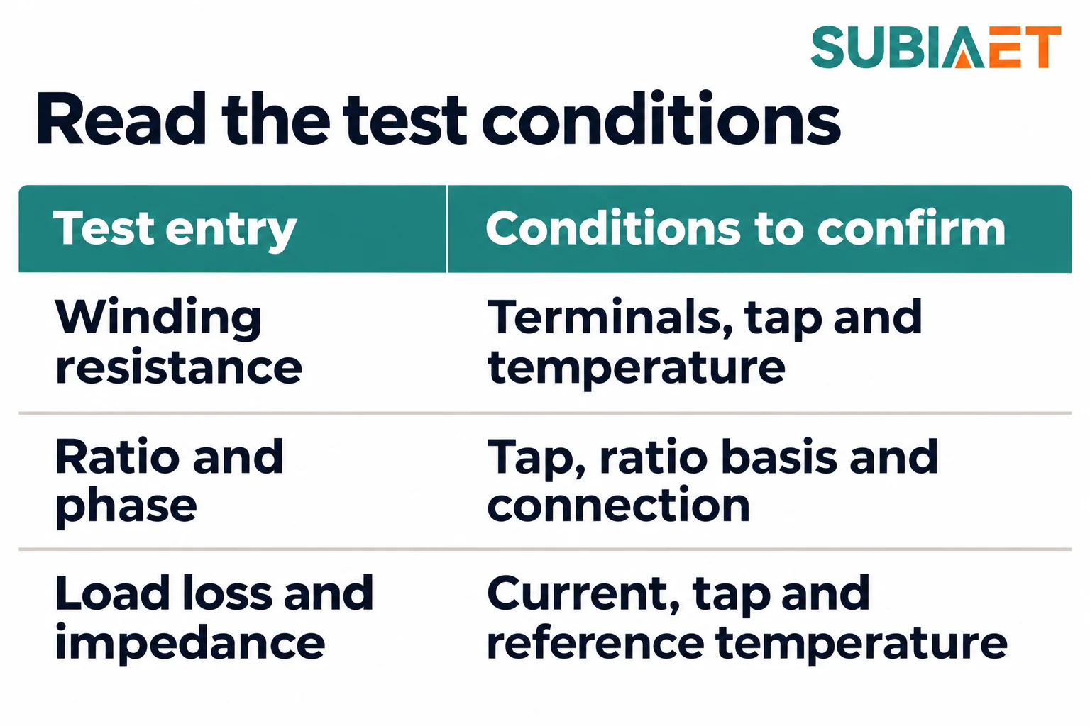
Winding resistance. Expect the terminals involved, the tap position, the units, and the temperature or thermal condition at which the measurement was taken. Resistance readings can support phase or reference comparisons and loss correction, but first establish the winding connection and measurement convention. Conductor resistance changes with temperature, so readings at different temperatures cannot be compared without accounting for their conditions and the applicable method. Look for the condition on the row or in an unambiguous applicable note; the location alone does not determine whether it is usable. In the public ABB specimen report used here purely as a format example — a different transformer in an IEEE/NEMA context, whose ratings and identifiers must not be carried into your own case — the winding-resistance rows carry the ambient condition, while load loss and impedance rows specify a reference temperature even under the measured-data heading.
Ratio and phase displacement. Check each required tap against the expected ratio on the same basis. Confirm whether a reported ratio refers to terminal voltages or winding turns; the winding connection affects that interpretation. Phase displacement is a separate recorded result to check against the ordered connection group. For Dyn11 under the usual positive-sequence clock reference, LV leads HV by 30°. A correct ratio does not dispose of an unexpected phase result: investigate the report, configuration and test information rather than accepting one row as proof of the other.
No-load loss and no-load current. Check the excitation voltage and frequency, the winding energized, and the units or reference base for the reported current. The test conditions must support comparison with the specified guarantee. If a measured value has been referred to another basis, establish the agreed method and its applicability instead of assuming that any off-rated test can be converted by a simple correction. Look for the condition on the row and in the report notes.
Load loss and impedance. Check the winding pair tested, the applicable current or rating, tap and stated reference temperature. When reviewing a correction, obtain the measured condition and the calculation basis as well. Load loss includes resistive winding losses and additional load-related losses; its reported value depends on the current and correction basis. For percent impedance, confirm the kVA and voltage base as well as the associated test conditions. The IEC definitions reproduced by GSO explain these quantities. If a row gives an impedance percentage without a tap, and there is no general statement elsewhere in the report fixing the tap for that test, you cannot tell which tapping the figure belongs to.
Dielectric results. Handle these separately from the loss and ratio family. Dielectric tests and insulation requirements refer to particular windings and terminals, so the record must name the test actually performed, the winding or terminal it was applied to, the test level, and the applicable conditions such as frequency and duration, with the outcome as required by the agreed specification. A dielectric section that reports “withstood” without identifying which insulation path was stressed is not fully reviewable, and the applicable levels and durations come from the project requirements, not from a general assumption. IEC 60076-3’s public scope describes dielectric requirements for particular windings and terminals.
Throughout, distinguish what kind of number you are reading. A directly measured value, a value corrected to a reference temperature, a calculated quantity derived from measurements, and a contract guarantee are four different things, and broad headings such as “measured data” or “calculated data” do not always separate them cleanly. A correction to a reference condition is distinct from the original measurement. Its direction and amount depend on the applicable calculation and loss components; do not infer the total corrected loss from copper resistance alone. A different corrected value is not in itself proof of an error.
One boundary worth keeping clear: a measured short-circuit impedance does not establish short-circuit withstand. Withstanding the thermal and dynamic effects of an external fault is a separate evidence question with the substantiation required by the purchase. IEC 60076-5’s public scope addresses thermal and dynamic withstand.
The comparison itself is mechanical once the basis is right, but the agreed comparison basis must remain explicit. The contract controls which reported values and allowances are compared — the Partnership Standardization Group purchasing specification, for instance, ties certified loss data to matching serial numbers, states test conditions, and defines its own limits and consequences. Your project’s limits may differ from any standard’s default, and any allowance the contract permits applies once, not twice.
Consider a training worksheet, not a real test and not a product: unit DEMO-08, 1,000 kVA, 11/0.415 kV, three-phase, 50 Hz, Dyn11, at the principal tap. The load-loss row, run at rated current with a recorded winding temperature of 28 °C, reads 8.10 kW measured. The worksheet assigns a corrected value of 8.90 kW at 75 °C. This value is invented for the exercise; it has not been derived from the 8.10 kW measurement. The fictitious project’s agreed maximum, inclusive of all applicable allowance, is 8.80 kW at 75 °C.
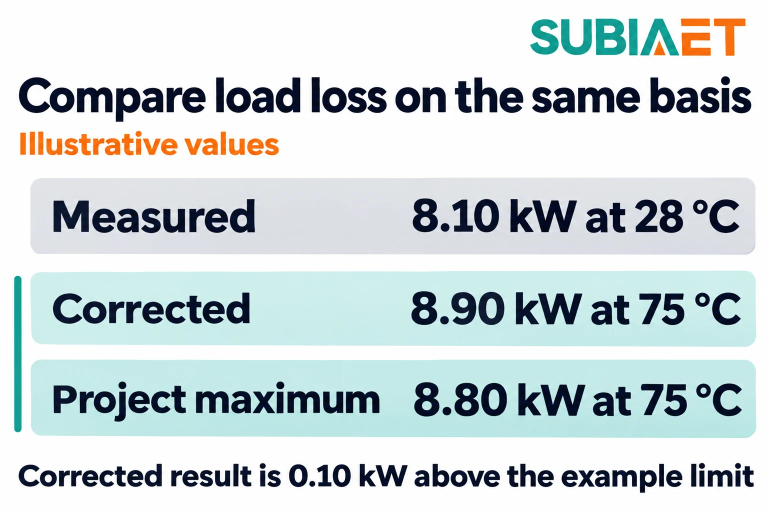
| Value | Basis | Use in the comparison |
|---|---|---|
| 8.10 kW | Measured at 28 °C | Not on the stated 75 °C comparison basis |
| 8.90 kW | Corrected to 75 °C | The supplier’s comparison value |
| 8.80 kW | Project maximum at 75 °C | The agreed criterion |
The comparison is 8.90 minus 8.80, which is 0.10 kW above the project maximum. That is a nonconformance against the agreed criterion on the agreed basis, and it calls for a documented finding and an authorized disposition — not comparison with the cooler raw value or a second allowance on top of the one already included. To verify a real correction, request its calculation and agreed method; the raw measurement alone is insufficient to reproduce the assigned value.
Two errors are easy to make here and both flatter the equipment. Comparing the raw 8.10 kW measured at 28 °C against a limit set at 75 °C makes a nonconforming unit look comfortable, because the correction that belongs in the comparison has been skipped. Adding an allowance that the 8.80 kW figure already contains produces a softer limit than the one actually agreed. Both errors produce the same false comfort, and both are detectable by asking one question of every row: what basis is this number on, and is it the same basis as the criterion?
The other failure mode is the opposite one — treating an unreviewable row as a failure. Suppose the impedance row in the same worksheet gives a percentage with no tap stated, and no general statement in the report fixes the tap for that test. You cannot decide whether that value meets the guaranteed impedance, because you do not know which tapping it belongs to. The correct action is to request the missing test basis and leave the item open. Do not assume the electrical result passes or declare it outside its electrical limit without that basis. A missing required report item may itself need documentary closure under the purchase requirements. An open item and a failed item lead to different conversations.
The scope of the evidence is part of the evidence. Terminology here is defined rather than improvised: a routine test is performed on each unit, a type test is performed on a representative design for requirements that routine tests do not cover, and a special test is agreed between the parties outside the routine and type categories, potentially on one unit or several as specified. Those are the definitions carried in the test classification in GSO’s public adoption of IEC 60076-1, and they tell you what a document is claiming before you read a single value.
The practical consequences follow directly. A routine report should exist for each delivered unit within the agreed scope, and it should be linked to that unit’s serial number. A type test report supports a design; its value to you depends on whether the tested design is demonstrably relevant to the configuration you purchased — a type test on a differently rated or differently constructed unit may say very little about yours, and the reasoning behind the relevance claim is what you should ask for. Special tests are whatever the parties agreed, so their absence is only a gap if the agreement required them.
A project factory acceptance test sits alongside this structure rather than replacing it. A FAT can include witnessed routine tests, additional checks, or configuration verification, with the scope agreed for the project. It is not a substitute for serial-linked test records, and for a prefabricated assembly you must distinguish the transformer evidence from the evidence covering the complete assembly. The agreed FAT scope establishes which checks and inspections were included. Witnessing a test also does not convert a missing condition into a stated one.
Resist the pull toward a universal checklist. What every unit must receive depends on the applicable standard edition, the agreed specification and the equipment’s role; scope abstracts and product pages do not establish conformity, and reading a standard’s scope does not make a report compliant with it.
By this point the review has produced a list, and every entry on it should be one of two types: a documentation gap, or a result outside an agreed criterion. They are closed differently.
For each entry, record the report revision, the serial number, the specific row or section, the purchase order requirement it is measured against, and the evidence needed to close it. Then choose the request that matches the gap. A missing identity link calls for a revised report or a serial mapping. A missing test condition calls for a clarification or a corrected row stating the tap, temperature, voltage or winding pair. A value outside the criterion calls for formal disposition under the contract — such as correction, retest or an approved concession, where authorized. Link the decision and closing evidence to the original finding and affected serial. A typographical error in a calculated column calls for a corrected issue.
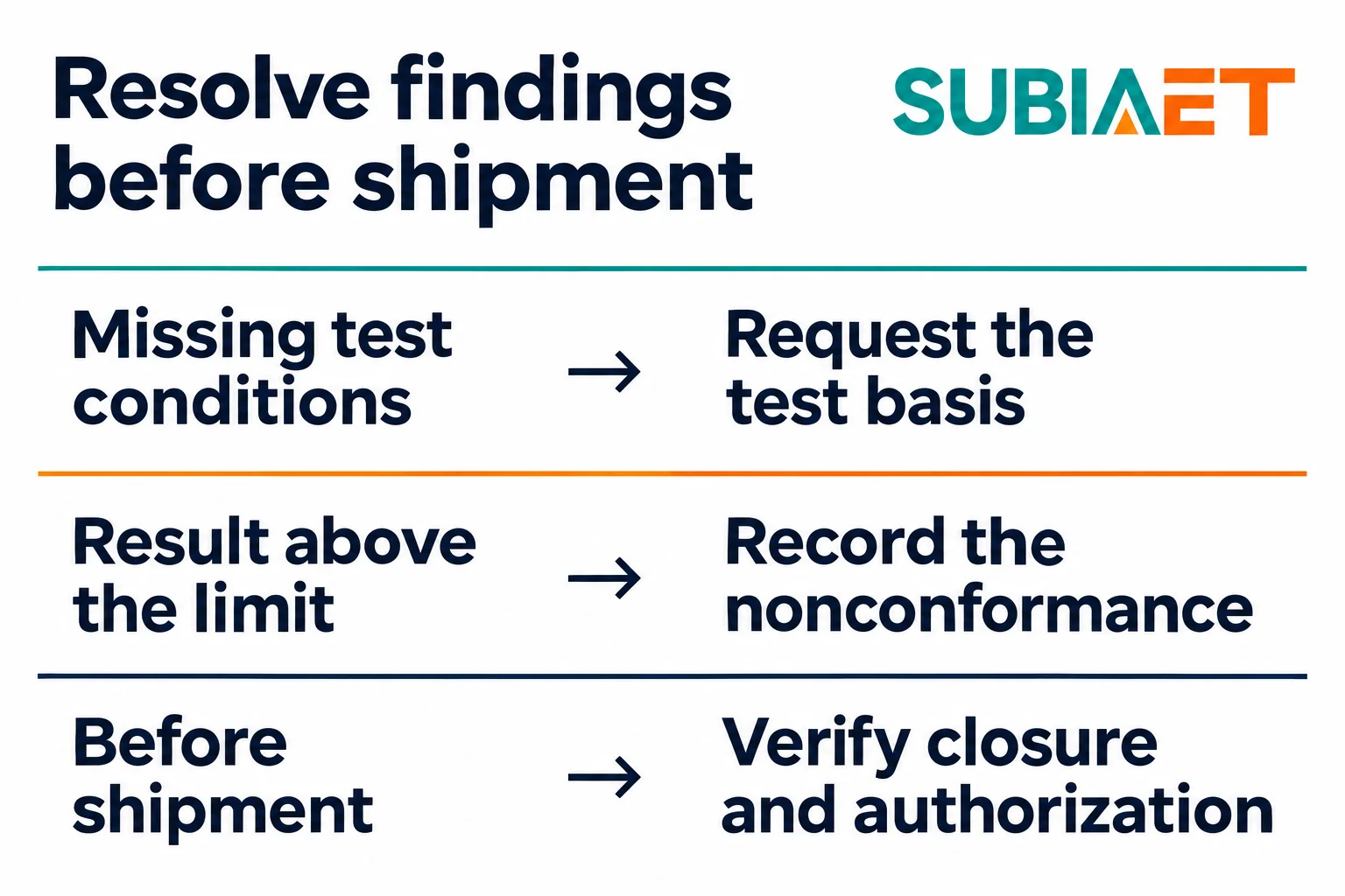
Then check the release path itself. If the contract requires witnessing or other hold points, confirm they were actually met rather than planned. Confirm that the person or function releasing the equipment holds the authority the contract gives them. A proposed change, a promise to send the corrected report after dispatch, or a verbal assurance from a project engineer is not an approval; the written disposition is. Released equipment is difficult to un-release, and a report corrected after shipment leaves a period in which the asset’s compliance status is undocumented.
It helps to record the closure evidence in the same place as the finding, so the review trail runs from the purchase order line, through the approved drawing revision, through the serial number, to the specific row and its resolution. That trail is what you will reach for if the transformer’s loss performance is questioned years later.
For the equipment side of the same decision — how a configuration is chosen and what data a supplier needs to quote it — see the industrial distribution transformer selection guide. For the commercial reading of the corrected loss figure you have just verified, the comparison of load loss and total cost of ownership across quotations explains how a verified kW converts into a purchasing decision. The transformer product family overview lists the current series if you are establishing which configuration a report should describe.
Use the tested serial number to identify the individual transformer. Trace it through the nameplate and factory records to the purchase order line, equipment tag and approved configuration.
The test measurement is taken under recorded conditions. A corrected value expresses it on a specified reference basis using the applicable method. Compare the value on the same basis as the contract limit and request the calculation if that basis is unclear.
An impedance result describes the transformer’s electrical impedance on the stated basis. Where the purchase requires evidence of thermal and dynamic withstand, request the separate evidence specified for that requirement.
Check the agreed test schedule. Type reports support requirements demonstrated on a representative design. Special reports cover additional tests agreed for the project and the units specified for them.
