Request a Quote
Share the equipment and project requirements. If you need help selecting a model, describe the application.
Have drawings or specifications? Email [email protected] with your project reference.

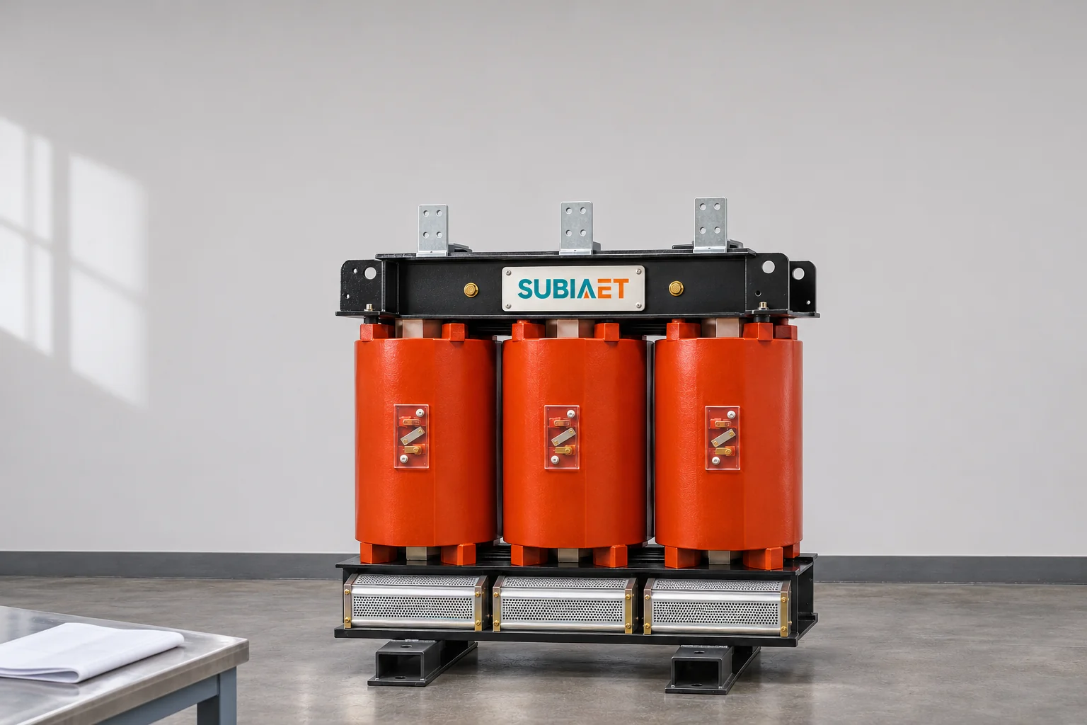
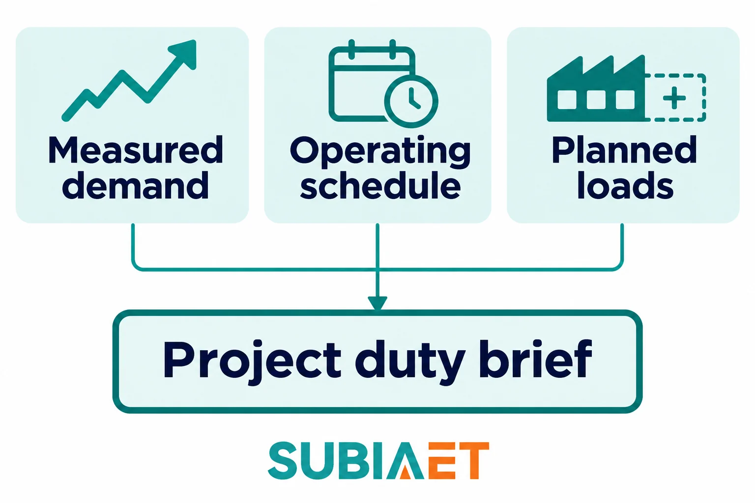
Before a shortlist of transformer ratings can mean anything, you need a clear picture of what the transformer will actually be asked to do. This sounds obvious, but one procurement error is working from installed capacity rather than actual simultaneous demand. A plant with 2,000 kVA of connected equipment may draw a fraction of that at any given moment, and the transformer selection should reflect the real operating condition, not the nameplate arithmetic of everything bolted to the busbars.
The starting point is measured demand where it exists. If the facility has a revenue meter, power analyser or SCADA historian, extract time-stamped load data covering a representative operating period. Look for the peak sustained demand, not an instantaneous spike during commissioning or fault clearance, and note how long that peak lasts. A compressor station that hits its peak for thirty seconds during start-up is a different duty problem than a smelter that runs at high load for twelve-hour shifts.
Where measured data is unavailable or the installation is new, build the duty from an operating schedule: which loads run simultaneously during each production mode, their typical load factors and the duration of each mode. A food processing line that runs three shifts continuously imposes a different thermal cycle on a transformer than a timber mill that runs one shift and then sits cold for sixteen hours. The transformer’s thermal mass and cooling system interact with these cycles, so the pattern matters as much as the peak value.
Alongside the sustained demand picture, flag these items for separate review before finalising your rating shortlist:
Schneider Electric’s transformer rating guide considers extensions and installation constraints alongside demand. Once you have simultaneous demand by operating scenario, peak duration, confirmed growth load and the flags above resolved or bounded, you can begin shortlisting nominal kVA ratings. The selection is based on the actual duty and the cooling basis you intend to specify, not an arbitrary multiplier applied to installed capacity. Standard rating series exist within most manufacturing programmes; your duty figure will fall between two adjacent standard ratings, and the question is whether the lower rating can be shown to handle the actual duty under the actual cooling conditions or whether the upper rating is needed.
If the project requires maintaining a defined essential load during a planned or unplanned outage of one transformer, establish what that essential load is and treat it as a constraint on the architecture decision — the number and arrangement of units — rather than adding it silently to the rating of a single unit. How service continuity requirements influence the number and rating of transformers is a project-level decision, not a default formula.
For projects that benefit from a worked load assessment example, the factory-expansion sizing walkthrough on the SUBIA site illustrates how measured demand, staged growth and coincident loading interact in an explicitly illustrative project scenario.
A transformer’s rated kVA is stated at defined reference conditions, including the applicable ambient, altitude and cooling mode. When the actual installation departs from those conditions, the available thermal capacity needs to be confirmed. Sending a kVA number to a vendor without also sending the site conditions means you may receive quotations that look comparable on paper but do not establish equivalent capacity in your plant.
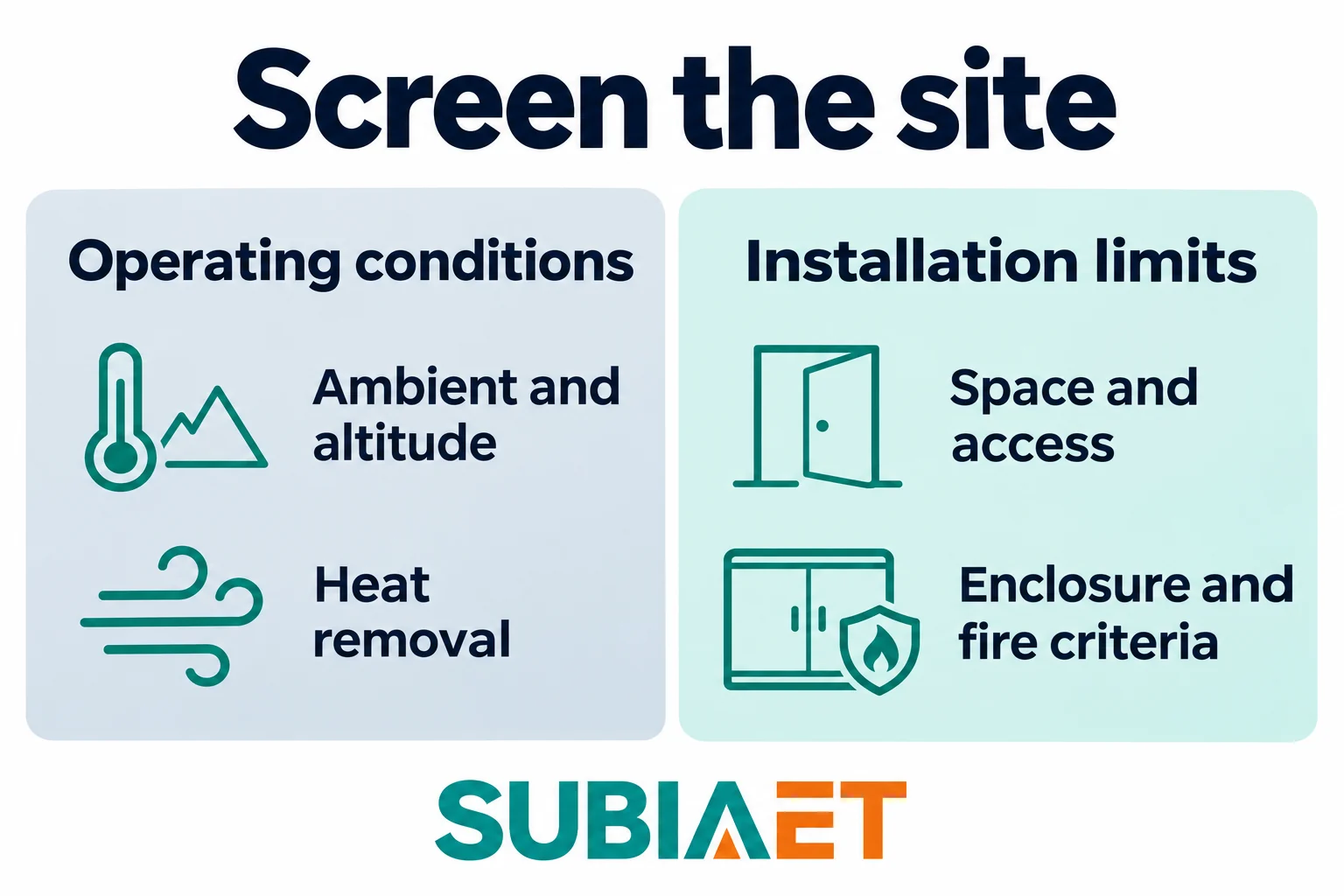
Ambient temperature is the most straightforward site parameter, but it requires care in industrial settings. A transformer room adjacent to a process furnace or in a location where hot air from machinery accumulates may have a significantly higher ambient than the outdoor design temperature for the region. Measure or conservatively estimate the actual ambient at transformer elevation during the peak season. For oil-immersed designs, ambient and load conditions together determine operating temperature and thermal ageing; for dry-type units, the same relationship holds through the winding insulation class and temperature rise rating.
Altitude matters because air density decreases with elevation, reducing the cooling effectiveness of air-cooled equipment and also affecting external insulation performance. Standards for dry-type transformers address altitude and environmental class as distinct rated parameters; ask vendors to confirm their proposed unit’s rating at your actual site altitude, not the standard reference.
Heat removal from the transformer room or enclosure is an underappreciated constraint. A naturally ventilated room relies on convective airflow to carry heat away from the transformer. If the inlet and outlet areas are insufficient, or if the room layout creates hot pockets, the effective ambient seen by the transformer will be higher than the external ambient. For forced-air-cooled designs, the cooling fans require clean, unobstructed airflow. Confirm that the building ventilation can handle the transformer’s declared losses as heat input before you finalise the room layout.
Location and footprint affect which transformer types are physically feasible. A transformer that must fit through a doorway, travel down a corridor or be lifted by a specific crane has defined dimensional limits before any rating comparison is relevant. Establish the transport route — not just the final installed position — including door widths, corridor heights, lift capacity and floor loading. For some industrial sites with constrained indoor spaces, this physical filter alone can narrow the shortlist significantly.
Enclosure and protection class translate site conditions into equipment requirements. A transformer in a clean, temperature-controlled electrical room has different enclosure needs than one installed in a dusty quarry workshop or in a coastal environment with salt-laden air. Dry-type transformers can be supplied with IP-rated enclosures for environmental protection; oil-immersed units have their own enclosure and containment requirements. Neither technology has a universal advantage in all installation contexts, and the correct choice depends on matching the proposed equipment to your actual site conditions rather than applying a blanket rule.
Noise is frequently overlooked until commissioning. Transformers generate audible noise from core magnetostriction and, where cooling fans are fitted, from the fans themselves. If the transformer will be installed near offices, control rooms or noise-sensitive areas, establish the required acoustic quantity, limit and measurement basis and include it as a requirement rather than relying on manufacturers’ standard values, which may be quoted on different bases.
Fire and containment criteria can determine whether a liquid-filled arrangement is acceptable in a given location. Building, insurance or internal plant requirements can impose conditions on equipment, fire protection, liquid containment and nearby exposure. Where a proposed arrangement cannot meet those conditions, it may have to be excluded or redesigned. An outdoor location still needs an assessment of fire exposure, drainage and service access. The technology decision should follow the installation requirements, not precede them.
When you send your enquiry, ask the vendor to state the rated kVA explicitly under the stated enclosure type, site ambient, altitude and cooling mode. This converts an abstract kVA number into a proposed capability that can be checked for your installation. IEC 60076-11 addresses enclosure, altitude and environmental conditions within its dry-type scope. The SUBIA oil-immersed transformer range and dry-type transformer range provide product context; for a systematic comparison of how the technologies respond to installation conditions, see the oil-immersed versus dry-type selection article.
A transformer of the right kVA, correctly rated for site conditions, can still be the wrong piece of equipment if its electrical interfaces do not match the system it must connect to. Interface mismatches range from obvious errors — wrong primary voltage — to subtle ones that only manifest under fault conditions or at the limits of the supply voltage range. Working through each interface before finalising the shortlist prevents late-stage redesign.
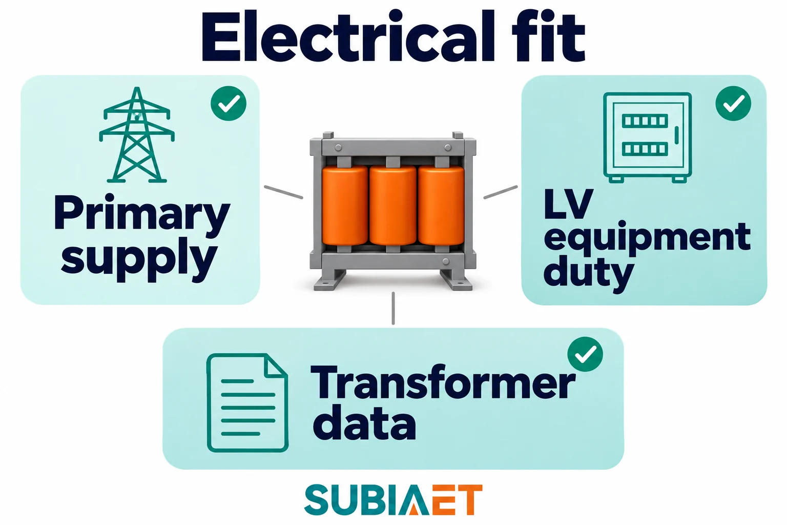
Match the transformer’s rated primary voltage to the utility or generation supply at the point of connection. Where the supply voltage varies within a range, check the proposed tap range and operating arrangement against that variation and the required secondary voltage performance. A fixed off-circuit setting and an on-load regulating arrangement address different operating needs. Confirm that the proposed unit can meet the required conditions rather than assuming a matching nominal voltage is enough.
Confirm supply frequency. This is relevant primarily on sites that import equipment designed for a different grid frequency or on sites with onsite generation that may differ from the public supply, but it is a quick check that closes a potential error.
Obtain available fault level data at the primary connection point from the network operator. This informs the required switchgear fault duties on the primary side and feeds into the fault current calculation at the transformer secondary.
The connection group describes the winding connections and the voltage phase relationship between sides. It also matters for system earthing and protection, but it does not establish those designs by itself. If an existing transformer is being replaced or another unit is proposed for parallel service, check the required phase relationship, actual terminal correspondence, ratio, impedance and neutral arrangement against the system drawings.
Percentage impedance is one of the parameters connecting the transformer to the downstream system. For the same rating and voltage base, a higher impedance magnitude reduces the transformer-only estimate of terminal fault current. Operating voltage drop also depends on the current, power factor and the resistance and reactance split; the magnitude alone does not establish voltage regulation. Evaluate both the fault and voltage requirements for the actual candidate.
Transformer impedance and system arrangement together determine the available secondary short-circuit current; the project team needs to verify that all downstream equipment — LV circuit breakers, busbar systems, cables and motor starters — has an adequate fault rating for the actual calculated level, using the transformer’s stated impedance and the actual upstream source conditions. This check uses the actual system design, not generic assumptions. Schneider Electric’s secondary fault-current example illustrates the transformer contribution and its stated assumptions.
Where parallel operation of two or more transformers is planned, impedance matching between units is an additional requirement. Units with significantly different impedances will share load unequally, and a unit with lower impedance on a common base can take a greater share of load. This needs to be assessed using the actual proposed units, not assumed to be acceptable because the kVA ratings match.
Confirm the secondary voltage, number of phases and neutral arrangement required by the downstream LV distribution system and the connected loads. For three-phase systems, establish the applicable earthing arrangement before specifying the secondary neutral connection and earthing provisions.
Check the physical termination requirements at both ends. The cable sizes or busduct cross-section that must connect to the transformer terminals determine the terminal box dimensions, lug sizes and access arrangements. A transformer with terminals that cannot accommodate the specified cable bundle within the required bending space and enclosure clearance needs its interface redesigned before procurement. Where a busduct riser connects directly to the transformer, the flanged connection geometry must be confirmed before procurement.
For the nameplate parameters and what each entry means in practice, the SUBIA nameplate reading guide explains how rated values on the transformer plate relate to these interface checks.
The purpose of issuing a common specification to multiple vendors is to receive replies that you can compare on a consistent basis. If each vendor interprets the requirement differently — using different reference conditions, different loss measurement bases, or different assumptions about what is included — price comparison is misleading and technical comparison is impossible.
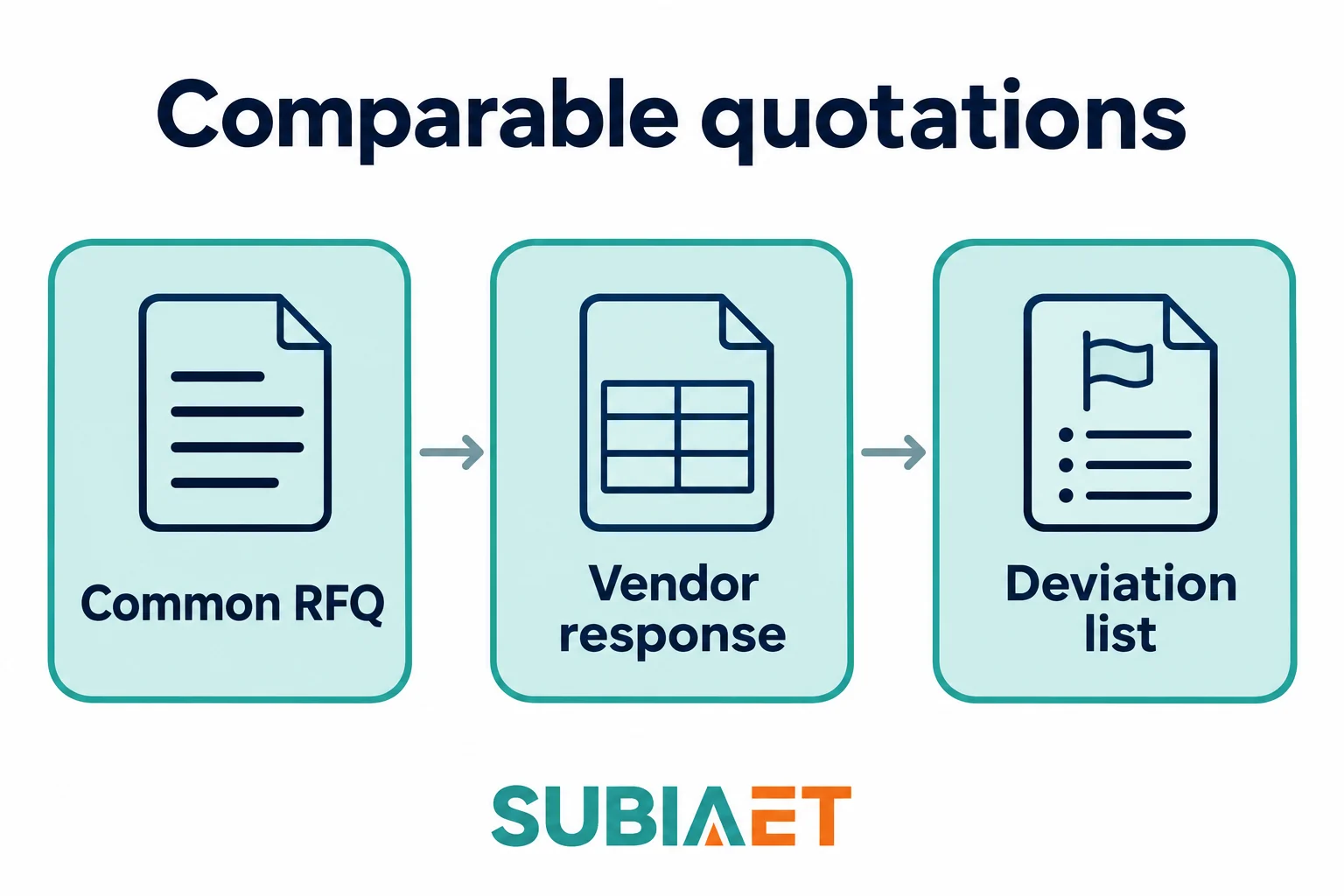
IEC 60076-1 describes a functional method of specification within its scope. Issue the same document to all vendors, identifying the applicable standards and editions. It should contain:
When responses arrive, the deviation list is the first document to review. Any vendor who has proposed a different cooling mode, a reduced tap range, a different loss basis or excluded a required accessory has not quoted on your specification. That departure may be acceptable with a price adjustment or a design change, or it may be a disqualifier, but it must be surfaced explicitly rather than buried in an assumption.
Consider this bounded scenario: two vendors both offer a unit with the same nominal kVA and the same primary and secondary voltage. The plant requires that duty at its design ambient with natural cooling. Vendor A confirms that basis. Vendor B quotes the same kVA with fans running. Ask Vendor B for its natural-cooling rating at the same site conditions and record the difference as a deviation. When the fans are unavailable, its declared fan-assisted capacity does not establish the capacity available for the plant. Resolve the departure before comparing prices. The difference can remain invisible unless the specification requires a stated kVA for each relevant cooling stage.
A second common comparison trap involves loss figures. If Vendor A guarantees losses at the agreed tap and reference conditions while Vendor B supplies typical catalogue data, the figures describe different commitments. Even two guaranteed figures need compatible test and reference conditions before they are used in an ownership-cost calculation. Confirm the guarantee, allowance and verification evidence required by the order before comparing the numbers.
Request that vendors fill a common data schedule — a table with identical rows for every required parameter — rather than providing free-format technical proposals. Free-format responses require more interpretation effort and make side-by-side comparison harder. A structured return makes gaps and departures visible immediately.
Before enquiring, confirm your project context:
– For factory-expansion load assessment context: transformer sizing for factory expansion
– For nameplate parameter explanations: how to read a transformer nameplate
– For technology comparison by installation conditions: oil-immersed vs dry-type selection
– For oil-immersed product enquiry: SUBIA oil-immersed transformers
– For dry-type product enquiry: SUBIA dry-type transformers
The stated rating can depend on the cooling mode, enclosure and site conditions. The offers can also include different losses, accessories and test documentation. Ask each supplier to respond against the same requirements and report any departures.
Use it to collect the existing ratings, then check current loads, supply, earthing, protection and terminal geometry against the project drawings and actual equipment.
Flag motor starts that could affect the plant’s voltage limits or sensitive loads. Share significant nonlinear load data with the transformer supplier and electrical designer so they can assess harmonics and heating.
Send the same provisional conditions to each vendor and identify which values remain open. Ask for the basis of the proposed rating and what needs to be confirmed before selection.
