Request a Quote
Share the equipment and project requirements. If you need help selecting a model, describe the application.
Have drawings or specifications? Email [email protected] with your project reference.

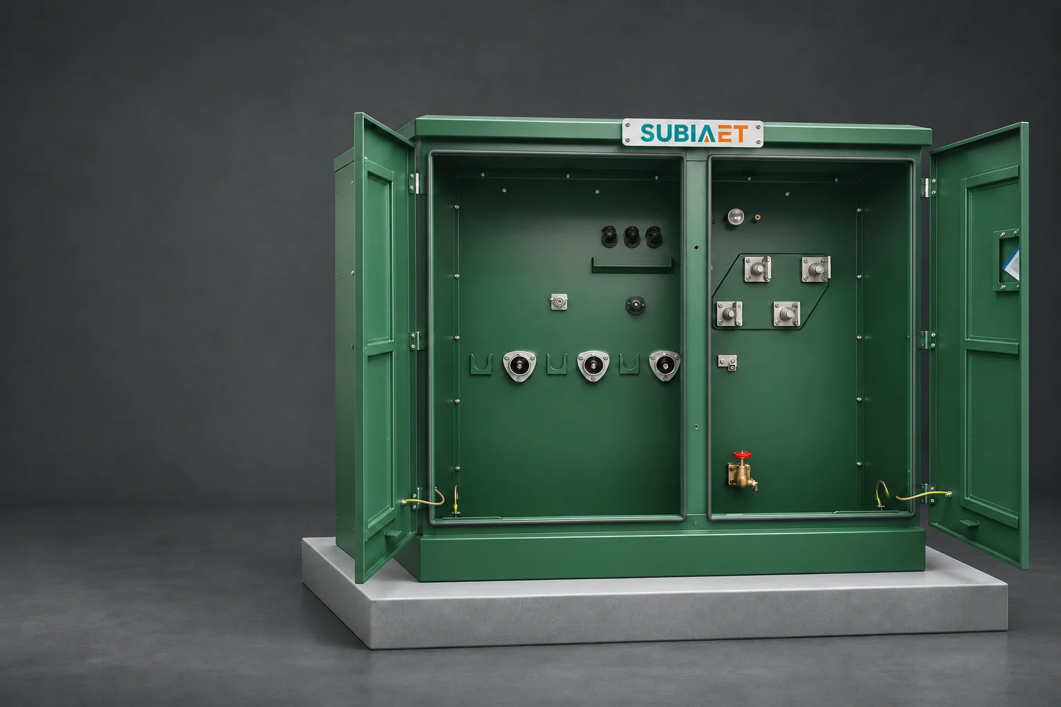
A pad-mounted transformer interface is settled by four separate attributes. A short label such as “loop feed” identifies only part of the requirement. The primary path — radial or loop — describes where the medium-voltage feeder goes when it reaches the cabinet. The termination construction — deadfront or livefront — describes what exists at the cable end inside the primary compartment. The connector duty — loadbreak or deadbreak — describes what the separable device is rated to do while the circuit is energized. The mating interface — voltage class, current rating, bushing or insert type, connector family — describes the exact geometry that lets a particular cable termination land on a particular bushing.
All four need to be explicit. Together they decide whether two cable sets can be landed, whether the utility’s existing accessories fit, and whether the unit can be operated the way the network is operated. A specification that stops at “loop feed, deadfront” leaves the exact mating interface and operating duty open.
The decisive step is to read the site single-line diagram, the cable schedule and the utility’s interface standard before looking at any enclosure photograph. Everything below follows from that order.
The primary-compartment drawing of a compartmental pad-mounted unit shows the medium-voltage connections: cable ways entering from below or from the side, a set of terminations, and behind them the switching and protection apparatus that connects those cables to the transformer winding. The number of cable ways and, especially, what connects them distinguish the primary arrangements.
Radial: one path in, no path out. A radial arrangement brings a single primary feeder to the transformer and stops there. The MV cable set, with its actual conductor count defined by the project cable schedule, lands on the primary terminations, and a tap carries the supply into the transformer. Nothing downstream depends on the primary continuing through this cabinet, because it does not continue. The site single-line shows the available supply and restoration arrangements upstream.
Loop: two cable ways and a separate tap. A loop-feed arrangement is a through arrangement. Two MV cable ways, one in and one out, are joined by a conductive path through the primary compartment, and a separate branch feeds the transformer winding. The actual switching and protection apparatus depends on the unit design. Loop feed does not imply a fixed number of switches or switch positions; obtain the offered internal single-line. Its through path carries feeder current straight past this transformer to whatever the outgoing cable serves, which is why the through path and the tap are rated and evaluated as two different duties.
What loop feed is not. A loop-feed cabinet is a piece of network capability, not a guarantee of a second source. Continuity of supply around a ring depends on the available alternative route, fault location, switching, capacity and protection. Two cable routes can share the same upstream source while providing an alternative path around a particular fault. Loop hardware alone guarantees neither an independent source nor automatic restoration. The reverse is also true and is often missed: nothing about radial operation forbids through hardware. A loop-capable cabinet can be specified for initial radial operation, with any unused interface fitted with its required accessories. If the second way is intended for a later stage, confirm that future arrangement explicitly. What a cabinet cannot do is provide a through path it was never built with.
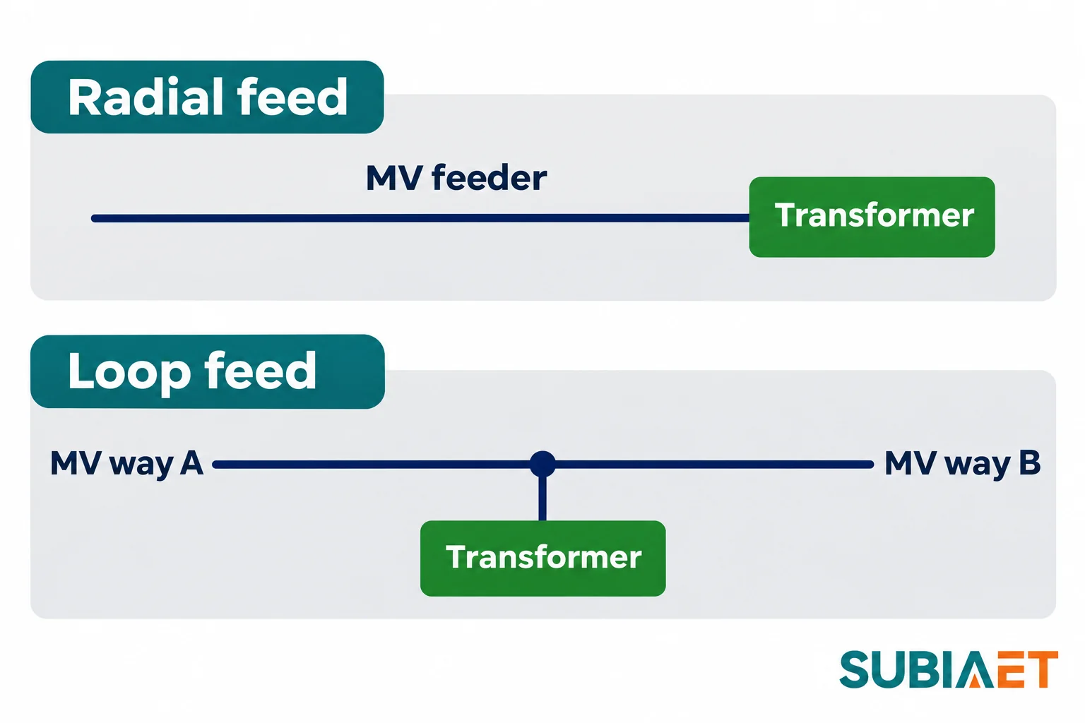
Where the answer actually lives. The site single-line diagram defines which arrangement is being bought, because it shows the normal configuration, the alternate configuration, the location of any normally-open point, and which device performs switching, isolation and protection. Compare that with the internal single-line for the exact unit. Two sets of terminations can also belong to a dual-radial design that selects one incoming feeder at a time and has no through path between the feeders. Eaton’s configuration guide illustrates both arrangements. The terminal count alone cannot distinguish them.
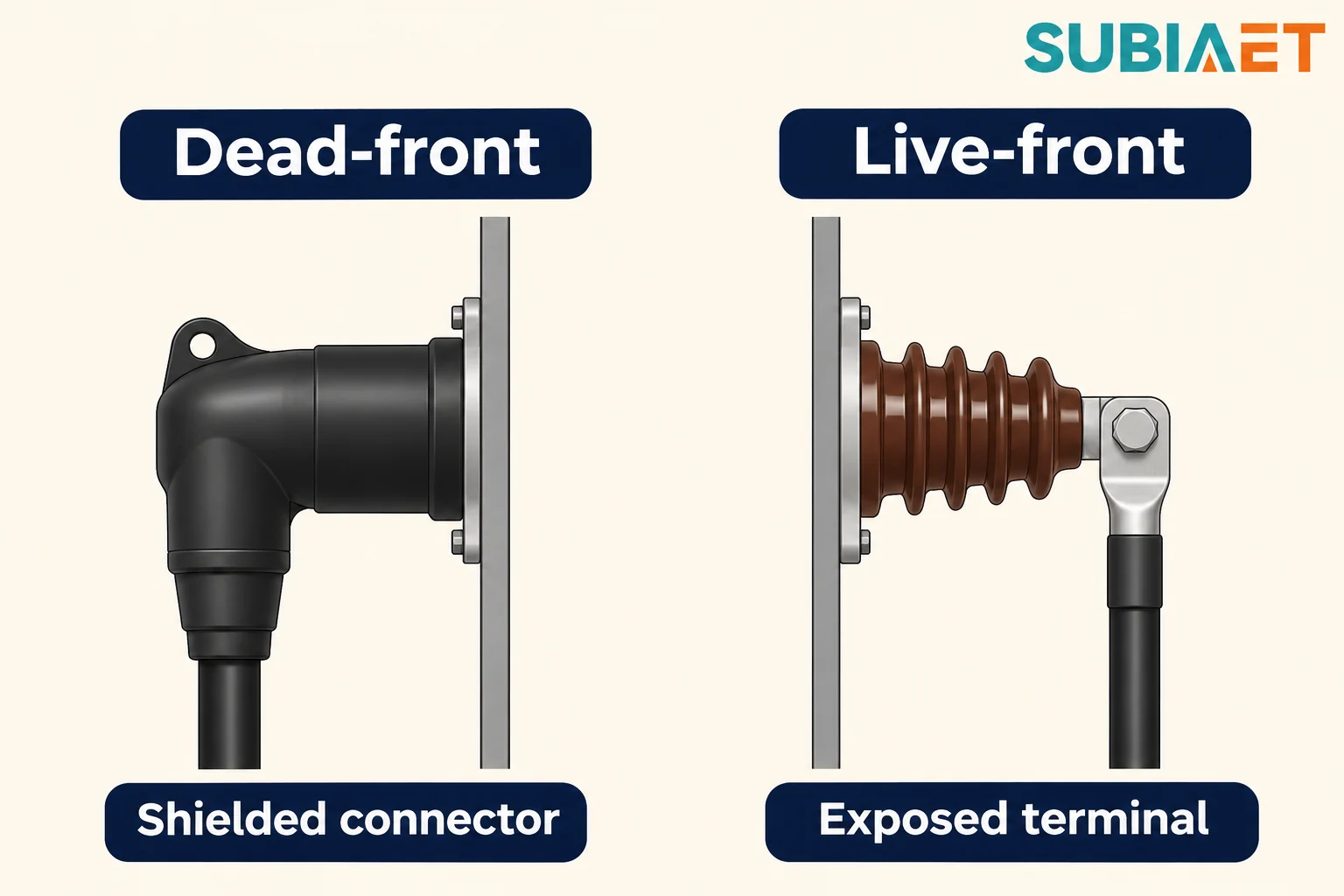
Deadfront and livefront describe the construction of the primary termination. Loadbreak and deadbreak describe what a separable connector is rated to do. These are separate axes, and both are separate again from the outer cabinet, the door and the lock.
In a deadfront arrangement, the transformer’s primary connection points are bushing wells with inserts, or one-piece apparatus bushings. The cable arrives terminated in a separable insulated connector that mates onto that bushing. In a compatible, fully mated assembly, the conductive contact is enclosed by the connector’s insulation and shield. Intact insulation and the specified shield and grounding connections are part of the installed assembly; mating alone does not establish those conditions or permission to touch it.
Two consequences follow. First, an unused apparatus interface needs the closure specified for that interface and duty; a cap and a standoff used to park a connector have different functions and are not interchangeable. Second, “deadfront” and “compatible connector” belong in the same sentence of a specification, because the transformer bushing and cable accessory are the two sides of the interface. Confirm who supplies and fits each part, and who verifies the complete assembly. The product label does not determine the shipping condition or installation scope.
A livefront arrangement can use porcelain primary bushings whose terminals stand exposed inside the primary compartment, with cable lugs bolted onto the studs. The compartment is enclosed and secured, but the termination hardware itself is bare metal when the unit is energized. Eaton’s transformer fundamentals illustrates the distinction. An enclosure is an access barrier; it is not an insulating covering over a terminal.
Both constructions can sit inside a pad-mounted enclosure. The SUBIA reference cabinet photograph shows distinct bays and visible connection faces with no project cables fitted, but it does not establish the electrical configuration offered for a project. Neither deadfront nor livefront makes a compartment touch-safe, and neither implies that opening the compartment is permitted. Deadfront changes what is exposed at the termination. It does not change what is exposed elsewhere in the compartment, and it says nothing about the conditions under which access is allowed.
A loadbreak separable connector is rated to be mated and unmated while the circuit is energized and carrying load, within its stated rating conditions. A deadbreak connector is intended for connection and disconnection when the circuit is de-energized. Both are device capabilities established by design and by test; neither is a permission to operate anything, neither says a compartment may be opened, and a separately rated fault-closing capability is different from interrupting fault current. A loadbreak designation alone does not establish fault-interrupting duty. Assign each switching, isolation, earthing and fault-clearance function to the equipment explicitly rated for it. The single-line should identify the connector’s permitted duty separately from the functions of switches, fuses, breakers and earthing devices.
Eaton’s interface guide, Figure 1 lists standard separable-connector interfaces that include a 200 A loadbreak interface and a 600 A deadbreak interface, spread across different voltage classes and with different apparatus fittings. It also lists a 200 A deadbreak case. Two lessons come out of that figure directly.
The first is that the same current number appears against both duties, so a current rating alone cannot identify the switching capability of a connector. The second is that the mechanical interface travels alongside the rating rather than being implied by it: two connectors with the same number on the label can belong to different systems. It would be equally wrong to treat 600 A as a synonym for deadbreak, because Eaton’s Cleer loadbreak connector system is a documented 600 A loadbreak example. A complete interface description therefore carries the voltage class, the continuous current rating, the duty, the specific bushing, insert or one-piece bushing type, and the connector family that mates with it — and no cross-brand compatibility should be assumed from any of those fields alone.
Consider a hypothetical distribution project with a single pad-mounted unit serving a load that sits partway along a feeder. Two MV cable sets land in the primary compartment because the feeder continues to a second transformer downstream. The utility’s interface standard calls for a 200 A loadbreak separable interface at the transformer primary, and it names the exact class and bushing profile as a separate requirement from the current rating. Two offers come back.
| Interface attribute | Project requirement | Offer A | Offer B |
|---|---|---|---|
| Primary path | Loop: two MV cable ways, through path, separate transformer branch | Radial: one feeder terminates at the unit | Loop: through path present |
| Specified interface | 200 A loadbreak, with class and profile named separately | 200 A loadbreak, matching | 600 A deadbreak |
| Duty | Loadbreak, per the utility standard | Loadbreak | Deadbreak |
| Outcome | — | Fails as submitted: the required through path is absent | Fails on mating and duty as submitted |
These are labeled example values used to separate two failure modes. They are not a catalogue of what any particular model offers.
Offer A fails on topology as submitted. Its interface is exactly the one the utility asked for, but the offered arrangement has no through path for the outgoing feeder. A cable accessory alone does not establish that missing path. Request a revised unit drawing showing the cable ways, terminations, internal connections and applicable switching or protection functions. Evaluate the revised arrangement against the same requirement rather than assuming that an additional cable entry makes it a loop-feed unit.
Offer B fails on mating and duty as submitted. Its topology is right: two cable ways, a through path, a transformer branch. But the utility’s cable terminations are 200 A loadbreak accessories, and landing them requires the matching 200 A loadbreak interface. A 600 A deadbreak interface is a different mating geometry and a different duty. Ask for the requested interface or a manufacturer-qualified alternative with its mating parts, ratings and duty defined. The revised arrangement needs acceptance under the project’s utility requirements. Do not assume that every alternative is impossible or that every accessory change requires a different network operating method.
Check current duty in two separate places. The through path and the transformer tap carry different currents, and both must be checked. The through path may carry the full feeder current for every downstream transformer, which can be several times the tap current of this unit, and it must be verified under normal and reconfigured conditions rather than only in the configuration the vendor assumed. The transformer branch must be verified against its own loading and protection. Check the applicable fault duties as well as continuous current; transformer kVA alone does not settle the through-path rating.
Cable compatibility is a third check. Conductor size range, insulation diameter, metallic screen and jacket construction, minimum bend radius, connector length inside the compartment, number of cables per phase, and the physical position of the cable way all have to line up with the cable actually specified. A connector rated for the current but too long for the compartment, or outside the cable’s insulation diameter range, is not a solution.
Assess adapters as an engineered interface. Two connectors with the same current rating from different manufacturers are not interchangeable unless the combination is documented as compatible. A proposed adapter creates an interface with its own ratings, space needs and approval requirements. Review the complete arrangement, including its mating parts and operating duty, and obtain acceptance under the project’s utility requirements rather than treating an adapter as a substitute for an interface specification.
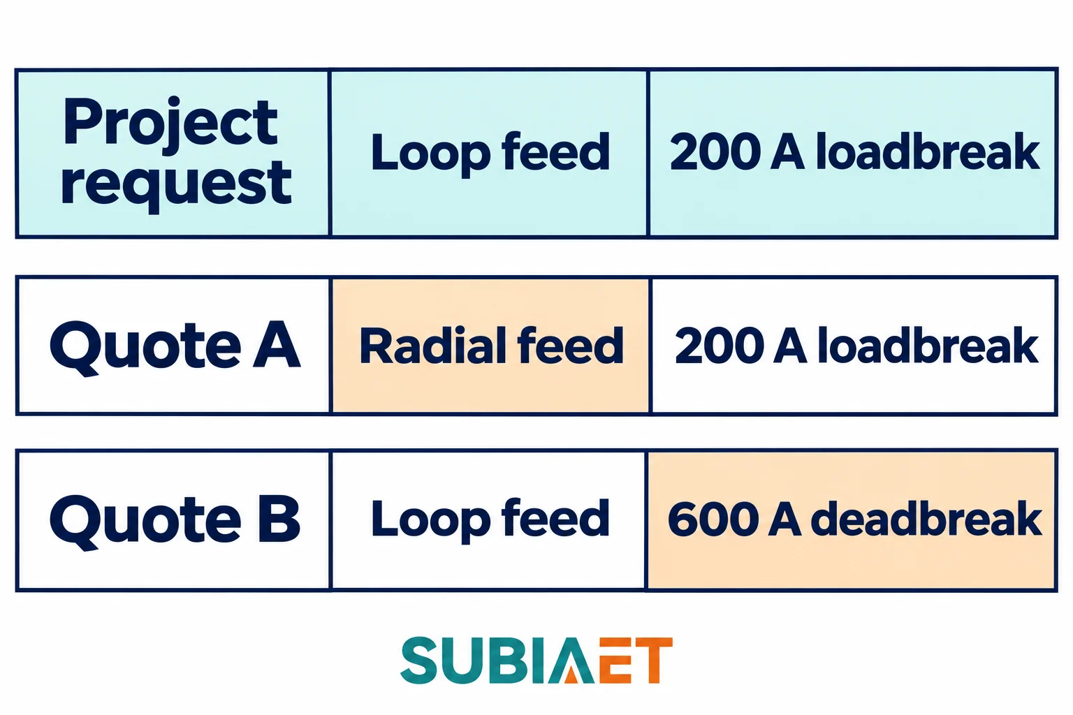
The productive move is to send both vendors the same requirement and compare what each says it would take to meet it, on identical axes: two cable ways, a through path rated for the real through current, 200 A loadbreak interfaces of the named class and profile, compatibility with the specified cable, adequate access, and a clear statement of who supplies and fits the accessories.
The SUBIA pad-mounted transformer page describes radial and loop-feed arrangements for the ZGS family. That is a family description. The kVA designation does not determine topology, connector duty or mating interface, and a product photograph cannot prove an arrangement. The reference cabinet image shows separated bays and visible connection faces with no project cables fitted, which tells you where to look, not what has been selected. Verify the connection arrangement on the drawings for the exact unit offered.
So an enquiry has to be converted into documents. Six items do most of the work:
The low-voltage side belongs in the same package. Number and type of LV terminals, current per phase, neutral arrangement, the ground pad and what the installer must bond, and whether the neutral is brought out as a full terminal or a bar all affect the interface the site crew will actually work to.
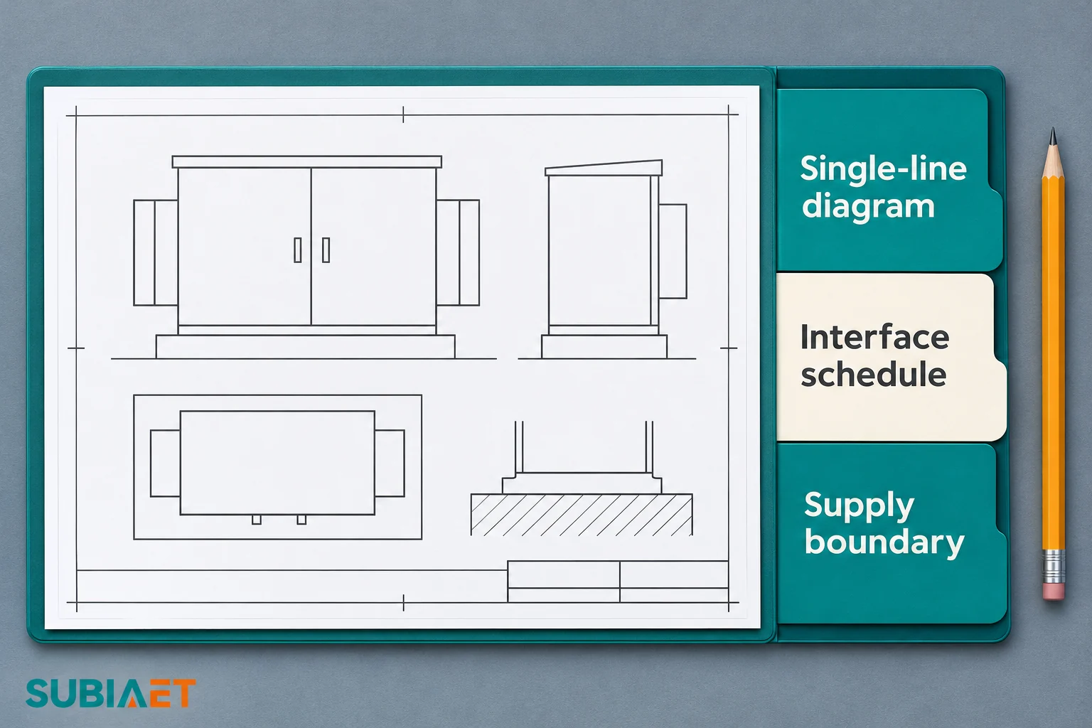
Define the pad-unit and packaged-station scopes. A pad-mounted transformer can incorporate selected MV switching and protection, so those functions are not excluded by the product name. A packaged station can combine MV switching, the transformer and LV distribution into one coordinated assembly. If the enquiry covers that complete package, identify the boundary at the station and record the equipment and internal connection responsibilities in its supply schedule. The label alone does not establish which components are included or who supplies every connection.
If the single-line shows a through path, start from the pad-mounted transformer family page and ask for the compartment arrangement drawing for the specific unit rather than the family overview. If the network design, the normally-open point and the switching sequence are still open questions, the ring main unit discussion covers how the ring side is organized and where its boundary sits. If the project is packaging MV switching, transformation and LV distribution as one assembly, the prefabricated substation pages describe that scope, and the components-and-power-flow introduction explains how the pieces inside the package relate. For a plain-language walk through the equipment itself — bays, terminations and typical applications — the pad-mounted transformer introduction is the gentler starting point, and the utility secondary distribution section covers the application context these units sit in.
The SUBIA prefabricated substation range provides the related package context. The pad-mounted transformer introduction covers the cabinet and its bays. The ring main unit guide explains how the upstream ring and its switching fit into the network.
Loop feed describes the primary through path. Dead-front describes how the primary connection is enclosed by its insulating and shielding system. Confirm both on the drawings for the selected unit.
Dead-front describes the termination construction. Confirm the mating connector’s documented loadbreak or deadbreak duty separately. Neither designation grants access to an energized compartment.
A loop-feed unit can provide a through path. An alternate supply route depends on the network connections, available supply, protection and switching arrangements.
Compare the site and unit single-lines, the compartment drawing and the exact connector and accessory schedule. Record who supplies, fits and checks the terminations.
