Request a Quote
Share the equipment and project requirements. If you need help selecting a model, describe the application.
Have drawings or specifications? Email [email protected] with your project reference.

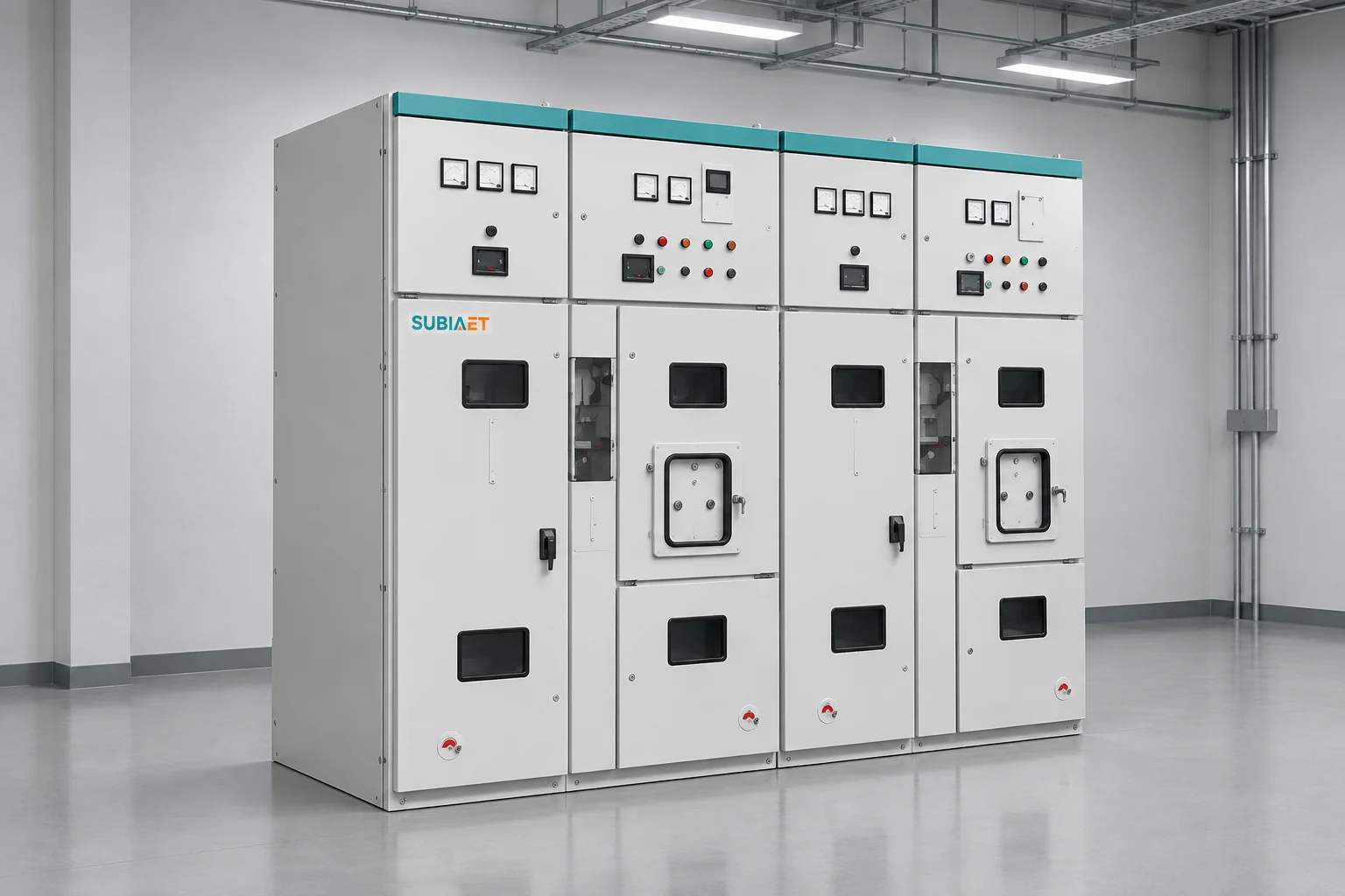
When a short-circuit study lands on your desk alongside two switchgear quotes, the comparison task looks deceptively straightforward: pick the higher kA number and move on. The actual task is more structured than that. A single kA headline conflates at least four different quantities — each attached to a different physical object, a different operation and a different basis of measurement — and a quote that wins on one quantity can still have an open gap on another.
This article walks through what each rated quantity measures, why the basis matters for each one, how to map study outputs to the right rated quantity, and how to apply that mapping to a worked example with two illustrative offers. The goal is to leave you able to identify which rating applies to which study result, and to identify where the evidence is complete versus where it still needs a question.
A switchgear assembly carries multiple rated duties simultaneously, and they describe different things.
Rated normal current is expressed in amperes. For the declared installation conditions, it describes the current the equipment can carry in normal service. Verify the load requirement and short-circuit duties separately.
Short-circuit rated quantities are expressed in kA, but kA alone is incomplete. Check whether the declaration uses RMS (root mean square) or peak (the instantaneous maximum). For breaking, the RMS figure refers to the periodic AC component. For short-time withstand, confirm the study’s equivalent RMS or thermal basis and the declaration it will be checked against. Using the wrong basis gives a number that cannot be compared against the corresponding study output. A 25 kA RMS figure and a 63 kA peak figure are not interchangeable — they describe different physical quantities at the same event.
Duration completes the thermal picture for the closed-path ratings. A short-time withstand declaration of 25 kA for one second and the same 25 kA for three seconds describe different thermal exposures. The assembly that passes the shorter test has not demonstrated equivalence at the longer time.
The problem becomes concrete when you map ratings to physical objects inside the assembly. The main power circuit through the busbars, the circuit breaker itself, the cable terminations or bushings, and the earthing switch are distinct objects. A single catalogue headline may come from any one of them, and may not apply to the others. The public scope of IEC 62271-100 concerns the breaker device and its direct making and breaking tests. The public scope of IEC 62271-200 concerns the prefabricated AC metal-enclosed assembly. Check evidence for the assembly configuration separately from the breaker. A catalogue table that separates main circuit, earthing circuit, busbar, breaker breaking, breaker making and assembly withstand into distinct rows is correctly structured. When a table collapses those into one headline, the gap is an evidence question, not an automatic pass.
A simplified single-line helps keep these objects distinct. Mark the incoming busbar, the circuit breaker and the paths it connects when closed, the outgoing feeder connection with any installed links or current transformers, and the separate earthing path with its own switch. Each segment on that diagram has its own applicable rating column in the quote comparison table. The common mistake is to compare only the breaker rating column and treat the rest as implied.
Breaking current describes the ability of the breaker to interrupt a fault — to part its contacts against a live short circuit and extinguish the arc so that current stops flowing. This is the most familiar kA number and also the most frequently misread.
The rated breaking current uses the RMS value of the periodic AC component. Schneider Electric’s explanation of the DC component identifies a separate associated aperiodic component condition. For the application check, match the study’s AC RMS value and associated asymmetry at contact separation to the breaker’s declared capability. Where the supplier gives a time constant, confirm how it applies at the relevant contact-separation time.
This distinction matters because the fault current waveform is asymmetrical at inception. The instantaneous value at the first peak is much higher than the RMS of the AC component. Matching the study’s first-peak value against the breaker’s RMS breaking rating would impose a standard that the breaker is not designed or tested against. The correct comparison is AC RMS breaking component from the study against rated breaking RMS from the breaker data sheet, with a separate check on whether the study’s DC component or percentage asymmetry lies within the declared conditions for the breaker.
Two additional conditions must be confirmed for a complete breaking check: recovery voltage and duty basis. Recovery voltage appears across the open contacts after current interruption. Check the transient recovery voltage (TRV) for the applicable fault and system configuration against the breaker’s declared conditions. Confirm the operating sequence and any specified duties, such as terminal-fault or short-line-fault interruption where applicable. The Eaton W-VACi technical table is one example of DC and TRV conditions appearing separately from the current magnitudes.
Breaking also needs to be distinguished from carrying. A breaker in the closed current path carries the fault current until the fault clears. Check peak withstand at the applicable peak and short-time withstand over the exposure. Which device clears the fault depends on the study case. Those are different rated quantities addressed in later sections.
When a breaker closes onto an existing fault, the early current peak can include a substantial decaying DC component. The making rating addresses the applicable instantaneous peak for that closing duty.
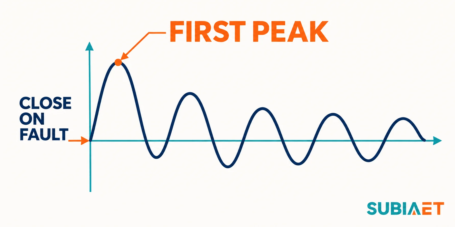
The closing angle influences the initial offset. For otherwise comparable conditions at the same frequency, a higher reactance-to-resistance ratio (X/R) means the DC component decays more slowly. Use the applicable peak from the study and compare it in kA peak with the declaration for the closing device and the specified service conditions.
The rated making current of the breaker must cover the making peak from the study. These are directly comparable in the same basis.
In a close-on-fault event, the same early peak can also stress the closed current path. Check the governing peak withstand case independently. Its topology or point of fault inception can differ from the making case. The busbar, the installed connections, the cable terminations and any other components that form the continuous current path at the moment of fault inception are all subjected to that instantaneous peak. The electromagnetic force between parallel conductors is proportional to the square of the instantaneous current; a large early peak can impose high mechanical stress on busbars, insulators and supports. Confirm the peak withstand for the applicable current path. For example, the Eaton HMH technical specifications list busbar peak withstand and breaker short-circuit closing peak as distinct fields.
The practical consequence is that you need to check both: the breaker making rating (what it can close into) and the assembly peak withstand (what the closed structure can survive). Both declared values must cover their respective study cases.
Once a fault has occurred and the breaker in the faulted panel has closed (or was already closed), the fault current flows through the closed path until a protective device operates to clear it. Faster clearance reduces the time the path carries the current. If primary protection fails, or if the applicable protection zone has an intentional delay, the required exposure can instead be governed by backup clearing.
The short-time withstand current is the RMS value the identified circuit can carry for its declared short duration. The symbol varies by document. Read the accompanying duration and definition. Both the RMS value and the duration are required to characterise the declared capability. A rating stated as 25 kA for 1 second and a rating stated as 25 kA for 3 seconds represent different exposures at the same RMS magnitude. I²t, the integral of current squared over time, helps describe thermal stress, but does not replace the manufacturer’s declaration.
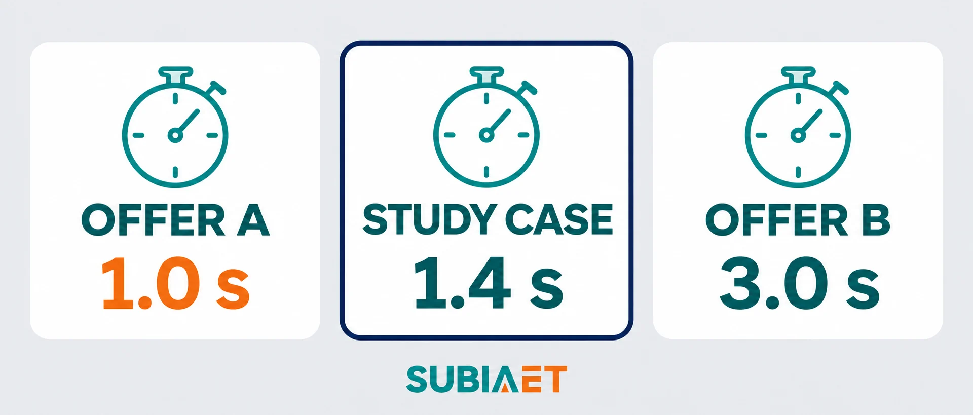
Comparing the RMS value on its own can hide a gap in the declared duration. A supplier may offer a large RMS withstand figure — say 25 kA — derived from a 1-second test, while the fault study shows that backup clearing could take 1.4 seconds. The 25 kA figure is numerically larger than the study’s RMS exposure, but the duration is shorter than required. You cannot bridge this gap by extrapolating: an assumed I²t equivalence alone does not establish a 1.4-second capability. Request an applicable current-duration declaration or other validated evidence for the exact configuration.
In the ABB VD4 manual, the listed 12 kV fixed breaker and the listed 12 kV withdrawable breaker for UniGear ZS1 both show 63 kA symmetrical breaking. The manual declares 63 kA short-time withstand for 3 seconds on the listed fixed breaker and 1 second on the listed withdrawable breaker. These are declarations for the two specified breaker configurations. Verify the complete assembly separately. The point it illustrates is general: same RMS, different duration is a real product differentiation that appears in published manufacturer data.
For the study input, identify the total required withstand exposure. Measure the exposure from fault inception to interruption for each applicable scenario, including detection, any intentional delay and the interrupting device’s total clearing time on the agreed basis. If backup clearance is required, assess that scenario separately. Match each case’s duration and current to the path that actually carries it.
The public summary of IEC 60909-0 gives its scope for calculating three-phase AC short-circuit currents at 50 or 60 Hz. Confirm the project’s specified study method, edition and cases. Ask for the outputs needed to check each equipment duty. Understanding how to extract the right number for each rating comparison requires knowing what the study computes and why each result differs from the others.
The fault current waveform after inception consists of two parts: a symmetrical AC component, which can change after inception, and a decaying DC offset. The point on the voltage waveform when the fault begins affects the initial offset. The network time constant affects its rate of decay.
The breaking component the study provides for breaker checking is the AC RMS value at the contact-separation time — the symmetrical component that the breaker must interrupt. At typical protection and breaker operating times, some DC offset may remain, and the study should state the asymmetry or DC percentage at that time. This is what gets compared with the breaker’s rated breaking conditions. The first-peak value describes a different duty and has a different basis.
The making peak is the maximum prospective peak for the applicable close-on-fault case. Compare it with the breaker’s peak making rating. Check the maximum applicable peak in the closed path against its peak withstand declaration, using the governing study case for that path.
The short-time withstand check uses the agreed equivalent RMS or thermal exposure for the study case and its duration. If the study quotes an equivalent RMS value at the actual exposure time, that is what is compared against the assembly’s declared short-time withstand at the stated duration. If the handover gives only the initial AC value, request the thermal equivalent or other agreed current-duration basis for the actual exposure. Account for how the AC and DC components change over the applicable interval.
The practical consequence is that no universal factor converts between these quantities. The study must state each named duty explicitly: AC RMS breaking component (with DC percentage or time constant), separate making and closed-path peak requirements, and RMS withstand at the required duration. Applying a fixed multiplier from one to deduce another ignores the system-specific X/R and time constants. The applicable study edition and the defined operating cases govern what the study computes for the actual system topology.
A complete rating check covers every segment of the current path that will carry the fault, not just the breaker interrupt function.
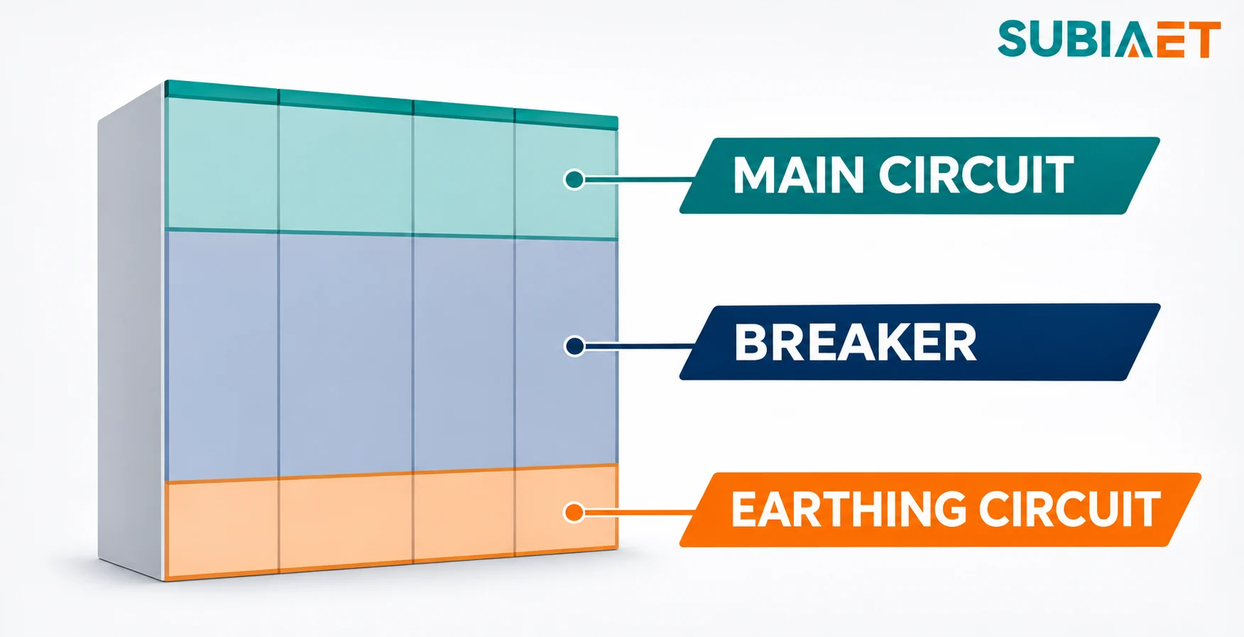
The assembly consists of several physically distinct components, each with its own declaration:
Main circuit — the busbar run, the interconnecting conductors and the breaker itself, as an assembled system. The assembly standard addresses the complete prefabricated enclosure and its current-carrying structure. The main circuit short-time withstand declaration covers this path at the declared RMS and duration.
Breaker — the interrupting device has its own rated breaking, making and short-time withstand, declared under the circuit-breaker standard. The breaker short-time withstand applies when the breaker is closed and carrying current without interrupting; this may differ from the assembly declaration.
Cable terminations or bushings — the interfaces between the assembly’s internal busbars and the external cables are part of the current path. Some assembly declarations explicitly list terminal or bushing variants separately. A change in the installed termination type may affect the applicable rated value.
Current transformer and accessory interfaces — a fitted CT has its own short-time ratings, and the assembly evidence must cover its installation, primary connections and applicable mechanical support.
Earthing circuit — the earthing switch has its own making and short-time withstand duties, which may differ substantially from the main circuit. These duties can include making onto an energised circuit under the stated fault conditions and carrying the applicable current until it clears. As illustrated in the Eaton HMH series catalogue, which states main and earthing circuit short-time withstand separately as distinct table fields, these are explicitly separated declarations. Check any required earthing-switch making capability separately from the short-time withstand of the earthing circuit. Request evidence for the exact switch and path.
Internal arc classification — some assemblies carry a notation of a kA value and a duration associated with internal arc classification testing. This is a separate scope from the short-circuit carrying duty. The declared internal arc classification has its own test conditions and accessible sides. Use the short-time withstand declaration to verify current carrying capability for a fault. If the notation appears in a quote, confirm which test scope it refers to before using it in the fault current comparison.
The correct review structure is to lay out each assembly component as a row, then confirm that the applicable rated quantity and declaration for each row covers the study’s requirement for that specific path.
The worked example below uses stipulated illustrative values for one identified MV bus. Both offers use the same service voltage, frequency and defined main current path. The duties and offer parameters are fictional training values, separate from SUBIA or vendor catalogue ratings.
Study duties for the identified bus:
| Duty | Quantity | Basis |
|---|---|---|
| Breaking AC RMS at contact separation | 17.8 kA | RMS (periodic AC component) |
| Close-on-fault making peak | 47 kA | Peak instantaneous |
| Closed-path peak withstand | 47 kA | Peak instantaneous |
| Closed-path RMS withstand | 18.2 kA | RMS |
| Closed-path required duration | 1.4 s | Seconds |
Note that the two 47 kA entries appear in separate rows with separate physical meanings. The making peak applies to the closing operation; the closed-path peak withstand applies to the assembly’s structural capacity to survive that force. On a real project these could come from different study scenarios. Do not assume they must be identical or treat the coincidence here as a universal rule.
Offer A:
| Rated object | Rated value | Basis | Study requirement | Screen |
|---|---|---|---|---|
| Breaker breaking RMS | 25 kA | RMS | 17.8 kA RMS | Passes numerically — subject to DC/asymmetry, TRV and duty conditions |
| Breaker making peak | 63 kA | Peak | 47 kA peak | Passes numerically — subject to applicable conditions |
| Assembly peak withstand | 63 kA | Peak | 47 kA peak | Passes numerically |
| Assembly short-time withstand | 25 kA for 1 s | RMS and duration | 18.2 kA RMS for 1.4 s | Gap: the declaration covers only 1 s |
The breaking and peak figures clear their respective numerical screens, subject to confirmation of the applicable DC component, TRV envelope and duty basis conditions from the specific breaker model documentation. The duration gap is real and cannot be resolved by the larger RMS figure. A 25 kA / 1 s declaration does not establish capability at 1.4 s; extrapolating by assumed I²t equivalence is not permitted, because the declared test envelope does not extend to the required time. To close this gap, obtain an applicable declaration covering 1.4 s at the required RMS level, or have the project protection team substantiate and approve a design that brings the required exposure within the 1-second declaration for this bus.
Offer B:
| Rated object | Rated value | Basis | Study requirement | Screen |
|---|---|---|---|---|
| Breaker breaking RMS | 20 kA | RMS | 17.8 kA RMS | Passes numerically — subject to DC/asymmetry, TRV and duty conditions |
| Breaker making peak | 50 kA | Peak | 47 kA peak | Passes numerically |
| Assembly peak withstand | 50 kA | Peak | 47 kA peak | Passes numerically |
| Assembly short-time withstand | 20 kA for 3 s | RMS and duration | 18.2 kA RMS for 1.4 s | Passes the stated current-and-duration screen |
Offer B lists lower headline figures than Offer A on the breaker breaking and peak columns, yet it covers the duration requirement that Offer A cannot currently demonstrate. All four numerical screens pass for the stated paths. This is a concrete illustration of why a higher headline kA does not automatically win the comparison.
However, numerical screens passing does not mean the offer is complete. Final selection remains open until the following conditions are tied to the evidence for Offer B: exact assembly variant and configuration, voltage rating and frequency, DC component and percentage asymmetry conditions for the breaker, TRV envelope, the specific connector or bushing variant included in the peak and withstand declarations, and any separate earthing circuit duties. Missing any one of these is an evidence gap — not a reason to assume failure, but a reason to send a specific question to the supplier.
The key methodological guardrails for this exercise: do not use the study’s first-peak value to check the RMS breaking rating; do not extrapolate from the 1-second Offer A declaration to 1.4 seconds using an assumed I²t factor; do not apply a universal peak factor to convert between quantities; and treat missing duration, missing RMS/peak basis or unidentified device model as an evidence gap that requires a supplier response.
A rating schedule approval commits the project to a specific assembly at a specific declared capability. The evidence supporting that approval needs to cover each study case, each rated object and each applicable condition. The following is what a complete request must specify.

Assembly identification: The exact assembly variant designation, panel module type, and configuration (fixed, withdrawable, ring-main, etc.). The same manufacturer series in different configurations can carry different short-time withstand durations, as illustrated by the fixed versus withdrawable distinction documented for specific ABB VD4 variants. A series name without a configuration is not a complete answer.
Device models: The specific breaker or switch model, the earthing switch model, and any fitted accessories such as current transformers with their own ratings. Each model carries its own applicable declarations; a family name without a model number cannot be verified against a test report.
Declarations and applicable test report references: The rated quantities listed in the offer must be traceable to a specific declaration document — such as an applicable rating schedule supported by the relevant type-test report reference and any documented applicability or extension to the exact offered configuration. A standard number by itself does not establish a rating. A catalogue page that lists generic series ratings is a starting point, not a final declaration. The test evidence must correspond to the specific configuration being offered, including the actual terminal or bushing variants.
Current path and interfaces: Which path is covered by each declaration — main circuit, earthing circuit, busbar, termination type. This is especially important if the assembly integrates current transformers, special bushings or cable sealing ends that are part of the declared current path.
Voltage and frequency: Confirm that the offered declaration applies at the actual system voltage and frequency. A rating declared at a different voltage level is not automatically applicable.
Study cases and clearing basis: Map each study scenario to the specific rated duty it exercises. Identify whether the breaking scenario uses the primary clearing time or a backup scenario, whether the making scenario uses the worst-case first peak, and whether the duration scenario uses primary clearing plus an allowed margin or the full backup time.
Asymmetry and recovery conditions: For the breaking check, confirm the DC percentage or time constant declared for the breaker model and whether it covers the system X/R at the fault bus. For the recovery voltage check, confirm the TRV capability at the actual service voltage and source configuration.
Deviations and limitations: Any footnotes in the offered data that limit the declared rating to specific conditions (such as a maximum fault level for a particular terminal variant, or a temperature derating for a specific ambient) must be explicitly confirmed as not triggered by the actual project conditions.
For each open line, record the study case, equipment and current path, required duty with its units, basis and duration, proposed model and revision, offered configuration, applicable declaration and test report reference, any deviation, and the owner and action needed to close it. When the answers arrive, preserve them exactly as stated — do not restate conditions in a generalised form that removes the limitation.
For further reference on MV switchgear configuration scope, see SUBIA’s medium voltage switchgear page. For transformer impedance as a study input that feeds the fault current calculation, see Transformer impedance explained. For how factory test evidence applies to the ordered assembly, see Substation FAT vs transformer tests. For transformer feeder protection architecture decisions that affect the clearing time inputs to the study, see Circuit breaker vs switch-fuse for transformer feeders.
Breaking current and making current are different operations, different physical quantities and different bases of measurement. The breaking rating is the RMS value of the periodic AC component that the breaker must interrupt at contact separation. The making peak is the instantaneous maximum current that occurs at the first half-cycle when the breaker closes onto a fault. The making peak can be higher because it expresses an instantaneous maximum and can include a substantial DC offset. The governing making and breaking cases can also differ. Comparing the making peak value against the RMS breaking rating would impose a standard that is not physically related to the interruption duty. The correct check is AC RMS breaking component from the study (at the contact-separation time and with its associated DC percentage) compared against the breaker’s rated breaking RMS and declared asymmetry conditions. These are separate columns in the check table with separate study inputs and separate rated values.
No. The declared short-time withstand envelope is specific to the tested duration. The I²t energy concept is a useful engineering approximation for understanding thermal effects, but a declared test result at one duration does not constitute evidence at a longer duration. The declaration applies to a specific circuit, duration and set of test conditions. Any extension needs documented applicability for the offered equipment. An assembly tested and declared at 1 second cannot be represented as passing a 1.4-second requirement on the basis that its kA is higher than needed. The correct response to a duration gap is to ask the supplier for an applicable declaration at the required duration, or to provide a documented protection design that changes the required exposure below the declared duration with traceable evidence.
The study should identify each quantity explicitly by its duty name and basis. Making peak current is a specific output from a worst-case closing scenario; it is the instantaneous first-peak value and is labelled accordingly. Closed-path peak withstand is the structural requirement that the assembly carries that instantaneous force without damage; it may come from the same or a different study scenario. Ask the study author to identify the initial symmetrical current, peak current, breaking current and associated DC component where those values apply to the review. Each refers to a defined case or instant. When a study output table gives a single kA figure without naming the duty, basis and applicable scenario, it is an incomplete handover. Request a study summary that names each duty, states RMS or peak, identifies the fault scenario and bus topology, and provides the DC percentage or time constant at the relevant contact-separation time. Using an unlabelled value in the wrong column of the equipment check table is one of the most common and consequential errors in the switchgear procurement workflow.
