Request a Quote
Share the equipment and project requirements. If you need help selecting a model, describe the application.
Have drawings or specifications? Email [email protected] with your project reference.

A purchasing team comparing two MV switchgear proposals for the same industrial feeder will often encounter a fixed-breaker panel and a withdrawable-breaker panel as competing options. Both can serve identical electrical duties. For maintenance and replacement, compare the isolation for a defined task, which adjacent equipment must be taken out of service and whether an approved spare can reach the cell and be accepted for return to service. This article works through those questions using the offered equipment itself, not a generic hierarchy.
Before comparing the two offers, hold the electrical inputs constant. Use the same required voltage, continuous and fault duties, protection scheme, busbar topology and cable interfaces. Actual nameplate values can differ if each offer meets the same requirements. Record any change to the electrical specification before comparing maintenance scope.
Having fixed the electrical inputs, separate the physical objects that may require service at different times and for different reasons:
These are four distinct service objects. A maintenance plan that addresses only one of them does not define the outage for the others. IEC 62271-200 covers the applicable metal-enclosed assembly. For continuity and access, identify the exact functional unit and compartment in the offer as well as the breaker mounting method. Use the exact assembly and functional unit classification from the offered panel documentation independently of whether the breaker is fixed or withdrawable.
A fixed breaker stays mounted at the panel’s fixed primary interfaces in normal service. An open interrupter stops current through its contacts. Establish the designated isolation boundary separately, using the actual devices, positions and verification required for that work. IEC 62271-102 covers applicable AC disconnectors and earthing switches. Its public summary identifies isolating distance, interlocking and position indication as distinct topics.
For a fixed breaker panel, isolation of the breaker work boundary therefore depends on the designated provisions in the offered design and installation:
The ABB UniSec SBC-W brochure includes an HBC functional unit with an integrated disconnecting device alongside its fixed breaker. The disconnecting function is part of the designed isolation arrangement, not a consequence of opening the breaker itself. The Eaton Power Xpert FMX brochure documents a service exchange option for the breaker on that fixed-technology platform. Check the actual isolation and access documents before assigning an outage to the exchange. The concept of fixed primary interfaces defines the mounting arrangement; it does not define what repair scope is permissible or what isolation arrangement is required.
The practical implication for an evaluator is to obtain the offered panel’s isolation diagram and confirm: which device provides the isolating function, where the earthing provision is, what the accessible compartment boundaries are, and which tasks the manufacturer supports under those conditions. Some fixed designs allow breaker removal for service without a withdrawable truck, but the access and isolation plan is design-specific. HSE’s switchgear guide HSG230 describes documented work and test boundaries, competent authorization and network drawings. Use the manufacturer’s instructions and the applicable site procedure and local requirements.
A withdrawable breaker panel mechanically separates the breaker carriage from the fixed primary contacts in the cell. The positions a carriage can occupy are manufacturer-defined, documented in position indication tables, and governed by interlocks specific to the design. They must not be assumed generic across brands or models.
Using documented examples:
ABB VD4 on a withdrawable part. The primary contacts are on arms on the carriage; they engage the panel’s stationary primary contacts in the service position. A multipole control plug handles protection, control and position indications. The manual distinguishes the breaker frame earth — which is established through the carriage’s rail interfaces in the test/disconnected position — from the circuit earthing switch, which establishes the earth for the designated primary circuit when the applicable conditions are met. These are not the same function. Same-version interchangeability is documented for these withdrawable parts; a carriage with equal physical dimensions but a different equipment fit can be rejected by control plug coding. Standard and optional interlocks depend on the actual panel and mounting frame.
Schneider Electric EvoPacT. This design defines four named states: connected, transport, combined test/disconnected, and removed/withdrawn. In the connected state, primary and secondary contacts are both connected. In the combined test/disconnected state, the carriage remains in the compartment, the primary connection is separated and metallic shutters close over the fixed primary contacts, while the secondary control circuit can be put in a manufacturer-defined test configuration that can energize the specified control functions for testing. The available functions depend on the ordered design and approved test plan. The removed/withdrawn state is a distinct mechanical condition achieved using a lift truck. The main interrupter open/closed state and the carriage position are explicitly separate parameters.
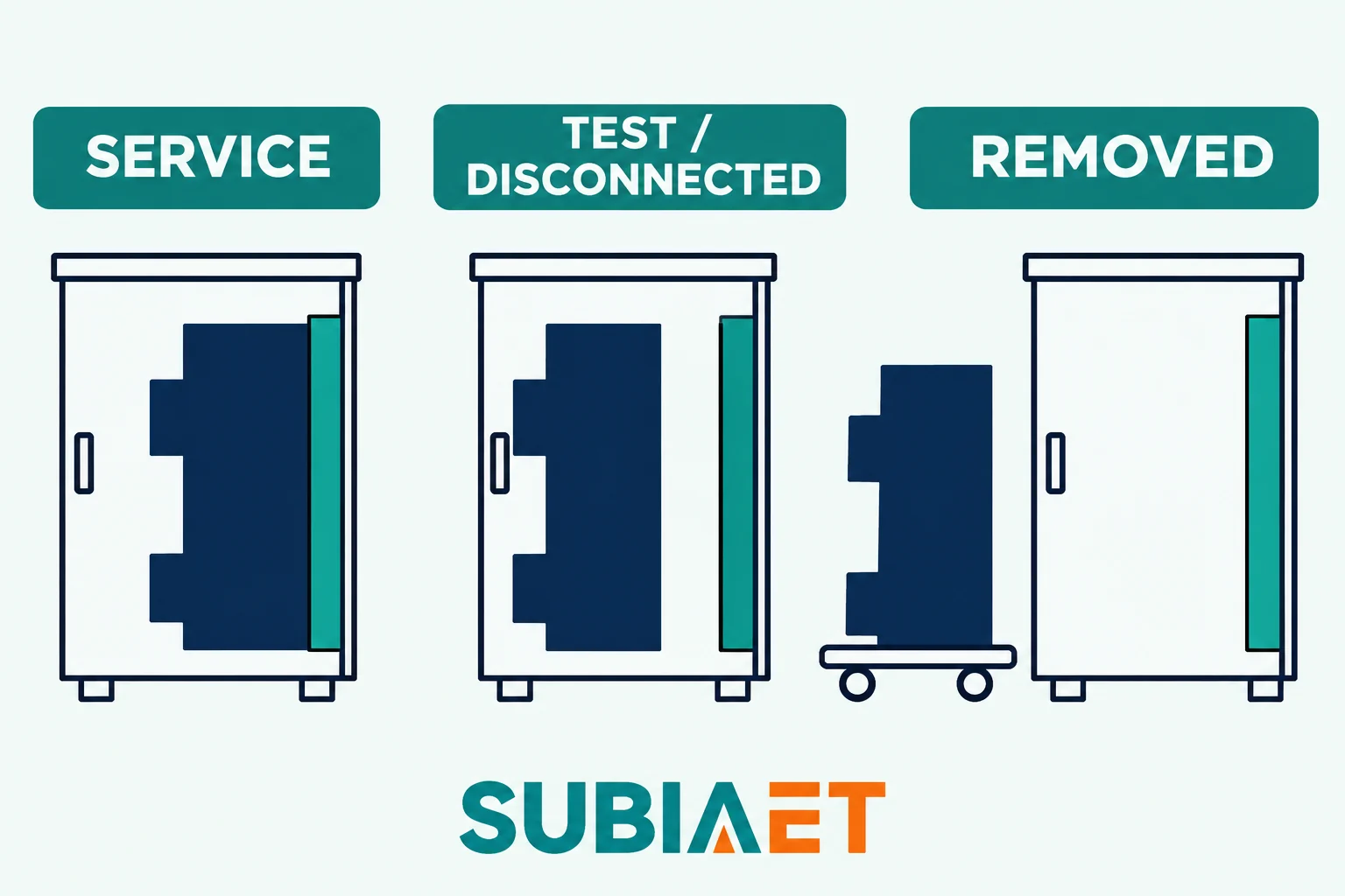
What these documented examples illustrate for a purchaser:
None of these positions establishes the state of the rest of the panel. The busbar, the cable compartment and neighboring feeders have their own conditions that must be established independently. For any work, including a breaker-only job, the authorized team must establish and verify the applicable electrical and physical boundary. A position table describes the unit’s state. It cannot verify bus or cable de-energization, establish circuit earth or authorize work.
Two classification fields in the IEC 62271-200 framework are frequently conflated: Loss of Service Continuity (LSC) and Internal Arc Classification (IAC). They address different questions.
LSC describes which functional units or bus sections can remain energized when a specified accessible high-voltage compartment is opened under stated conditions and with stated preconditions. The classification applies to a specific functional unit within the assembly. A withdrawable unit’s LSC category identifies how the assembly behaves for the particular accessible compartment the classification addresses — it does not automatically describe what happens when any other compartment is opened or when any other task is performed.
The cited ABB UniSec brochure shows this distinction directly: the SBC-W withdrawable functional unit carries LSC2A, while the WBC withdrawable functional unit carries LSC2B. Both are withdrawable. The two declarations illustrate why the relevant accessible compartment and remaining energized parts must be checked for each configuration. Record partition class separately. A fixed design can carry an LSC category that reflects its specific compartment construction, and a withdrawable design does not automatically carry a higher or lower LSC category by virtue of being withdrawable. Use the exact panel and functional unit declaration, not a generic inference from the mounting method.
IAC addresses the assembly’s performance in an internal arc event: the test current, duration, accessibility class and access sides it has been tested to. This says nothing about which compartments can be opened under normal maintenance conditions or whether adjacent feeders can remain supplied during maintenance.
Partition class is a third field. It identifies the applicable partition and shutter construction between the accessible compartment and main-circuit parts that may remain energized.
The practical rule for a purchaser is to obtain each of these three fields — LSC category, IAC declaration and partition class — from the offered panel documentation, with the applicable scope for each. Tie LSC to the functional unit and accessible compartment, and tie IAC to the declared assembly and installation conditions. No classification grants permission to work live, no classification guarantees system uptime during a maintenance event, and no classification substitutes for the site’s locally authorized isolation and work plan.
The outage scope for a maintenance task depends on the specific compartment accessed, the sources that must be isolated, and the physical boundaries of the work. A useful tool is a maintenance-object/outage matrix: list the work objects in one axis and the feeders or sections potentially affected in the other, then populate from the offered design documentation.
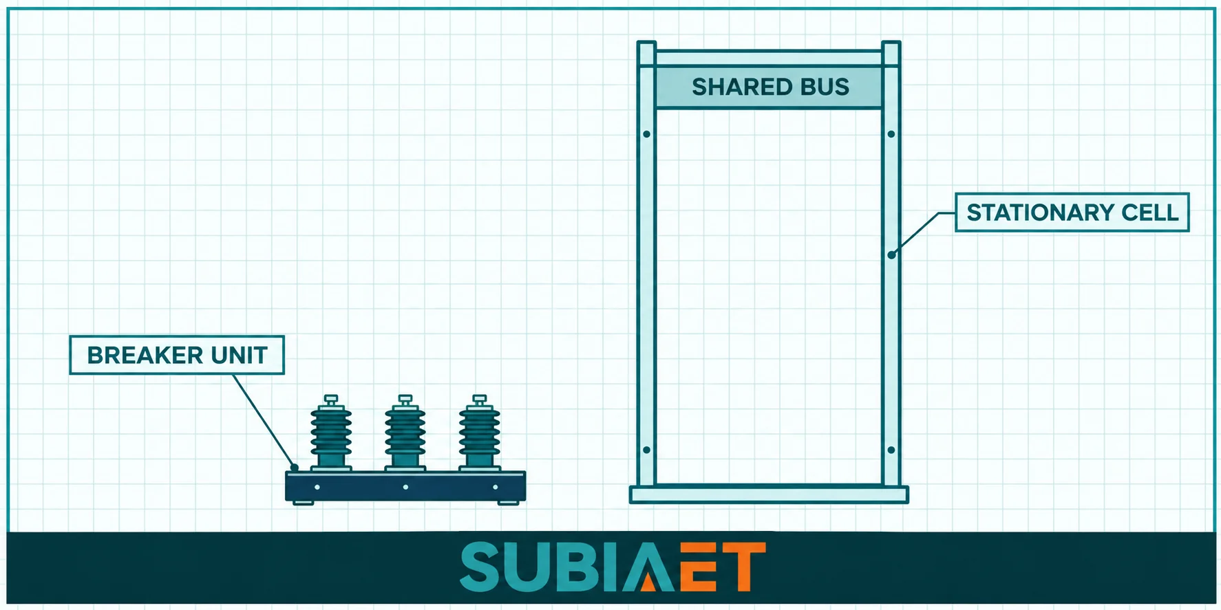
Consider the three distinct work objects:
Breaker-only work. If the offered design allows the breaker unit to be accessed, removed or replaced without opening any compartment that also contains live conductors belonging to adjacent feeders, then the outage scope can potentially be limited to the target feeder and its defined isolation boundary. For a withdrawable design, this is the scenario where the carriage-only job may be separable from the rest of the panel — but only if the specific panel declaration supports it and the site authorization covers it. For a fixed design with a service-replaceable breaker, the isolation arrangement defines which sources must be de-energized.
Stationary contacts, shutters, CTs or cable termination work. Once the work extends to the fixed parts of the cell — the stationary primary contacts, the shutter mechanism, the CT primary circuit, or cable termination and insulation — the access boundary changes. The carriage being absent does not mean the stationary compartment is accessible with adjacent feeders energized. The panel declaration must specifically cover this combination of compartment and energized/de-energized conditions. Depending on the compartment and sources, the job may require isolation of the bus section, cable-side sources or both. The approved scope determines the applicable earthing. The breaker-only access claim for the withdrawable design does not automatically extend to this category of repair.
Busbar work. Any work on the common bus section affects all feeders connected to that section. Withdrawal of a single carriage does not remove the connection between the busbar and the fixed contacts of that cell, and it certainly does not isolate the bus from the other feeders sharing it. For repair on the affected bus section, determine its isolation and earthing boundaries through the authorized plan. Any feeders relying solely on that section lose that supply while it is out.
Use the network diagram and work-boundary records described in HSG230 to identify all credible sources, backfeeds and alternative supply routes. This applies equally to both panel types. Any source that can re-energize the work boundary — including an open-loop interconnection, a generator, or a supply from a secondary side — must be included in the isolation plan.
A withdrawable design’s potential advantage in a breaker-only replacement job depends entirely on having a confirmed compatible spare available and a physically feasible extraction and insertion route at the actual site. Neither is automatic.
Electrical and mechanical compatibility must be confirmed at the level of the specific panel variant and the documented version of the breaker. For the ABB VD4 withdrawable, same-version interchangeability is documented — but a carriage with matching overall dimensions and a different internal equipment fit can be rejected by control plug coding. The coded multipole secondary plug carries protection, control and indication signals. A mismatch means the panel’s interlocks may not accept the spare, and the protection relay may not operate correctly. The evaluation checklist is:
A spare that passes most of these but fails on secondary pinout or interlock logic is not a usable spare until the discrepancy is resolved with the manufacturer.
The physical extraction and insertion route must be verified against the actual site, not the cabinet depth specification alone. The Schneider Electric MCSeT civil engineering guide distinguishes between operating space, mobile-part extraction space, and cubicle replacement space — these are separately sized. The extraction route for a withdrawable MV breaker carriage typically requires:
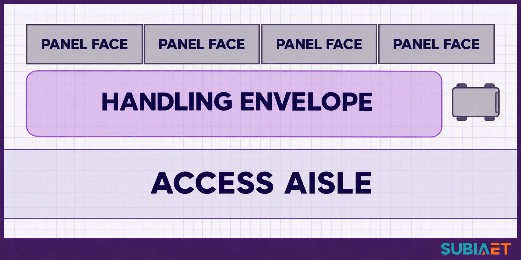
Cabinet depth tells you whether the carriage fits inside the cell. It does not tell you whether the building, floor, aisle and door arrangement can accommodate the extraction maneuver. This check must use the actual site drawings and the manufacturer’s civil requirements document for the specific panel model — not a generic rule.
Consider one industrial switchgear lineup with three feeders: F1 is the target feeder requiring a breaker replacement, and F2 and F3 share the same bus section. Both offers serve the identical F1 load at the same normal and fault duties, with the same protection scheme, supply and earthing topology, cable interfaces and plant requirements. F1 must be taken out of service for the breaker replacement job. The plant wants F2 and F3 available during that job, subject to the declared panel capabilities and approved work boundary. Assume no alternate supply for F1, F2 or F3. This is a fictional comparison.
Offer A is a hypothetical fixed-breaker panel with a manufacturer-defined isolation arrangement and a service-replaceable breaker. The submitted access plan for this particular breaker removal requires the common bus section to be taken out of service. A compatible spare can be delivered and handled through the documented service route in a scheduled section outage. The spare is confirmed compatible.
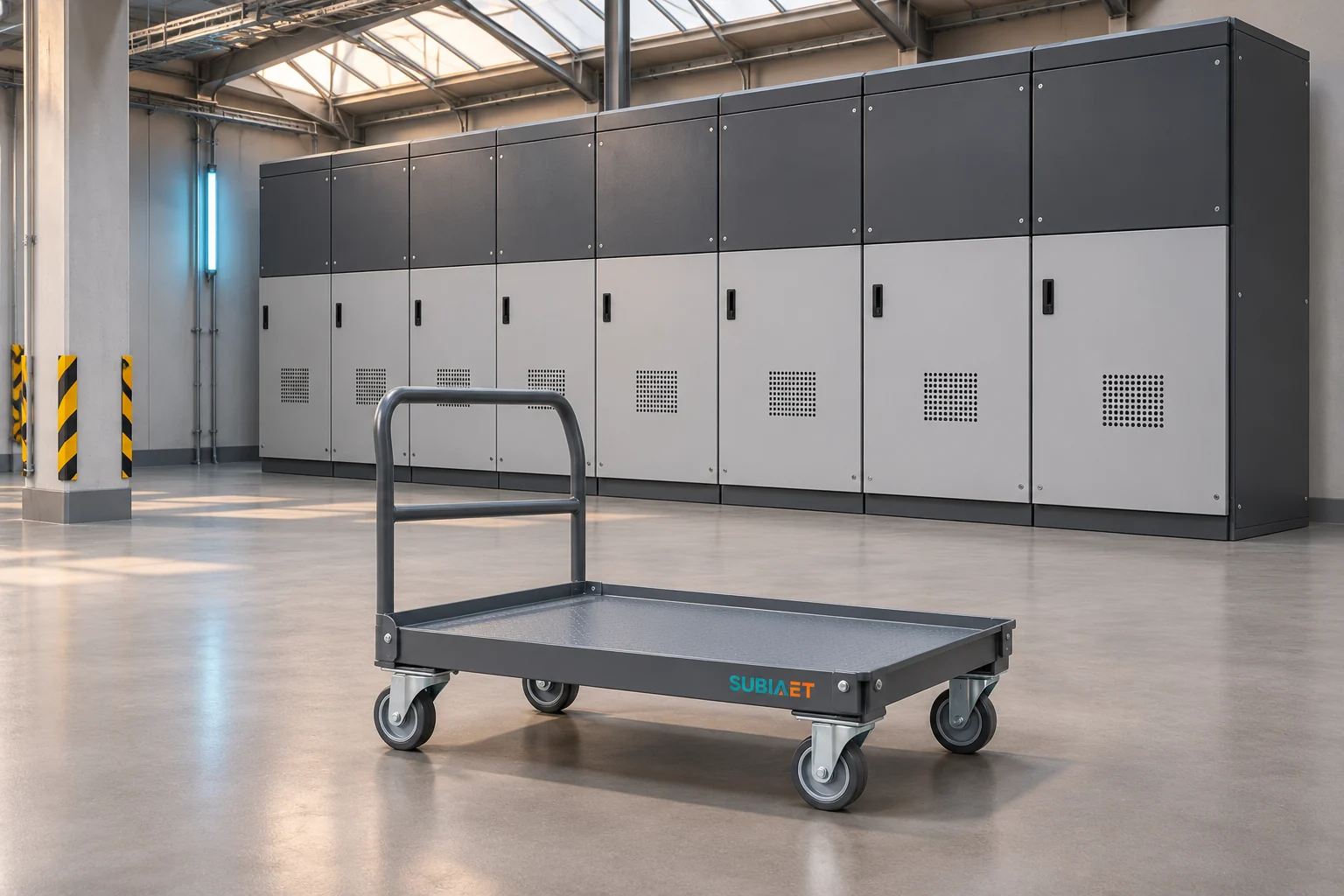
Offer B is a hypothetical withdrawable-breaker panel with a separable carriage. The supplier offers a breaker-compartment declaration for the defined breaker-only access task. The owner still needs the approved isolation and access plan, a confirmed compatible spare, the required trolley, working envelope and transfer route before crediting the narrower outage scope.

| Task | Offer A | Offer B | Missing evidence before deciding |
|---|---|---|---|
| Replace only the F1 circuit-breaker unit | The submitted job affects F1, F2 and F3 because this design requires a section outage for this task. | F1 is unavailable. F2 and F3 may remain supplied for this exact job only where the declaration, physical site conditions and approved work boundaries support it. | Exact offered compartment and current-path diagram, documented energized/de-energized boundaries, confirmed compatible spare and verified extraction route. |
| Repair a stationary primary contact, shutter, cable termination or CT | Evaluate the actual compartment access and all sources from the specific design; the breaker-removal plan cannot be generalized to cover stationary parts. | The carriage swap does not replace stationary parts. The breaker-only access declaration does not close the outage for this category of repair. | Task-specific compartment access documentation, affected current path and the approved isolation and maintenance scope for this work object. |
| Repair the shared busbar or address damage extending beyond the breaker cell | Assess the affected section and related equipment from the actual design and incident scope. | F1 carriage removal leaves the shared bus in place. With the affected section out and no alternate supply in this example, F2 and F3 also lose supply. Verify the condition of the remaining equipment. | Section boundary documentation, condition and inspection report, and acceptance scope for restored equipment. |
The conditional result for the F1 breaker-only task with the F2/F3 continuity requirement: Offer B becomes a candidate only after its access documentation and spare evidence close. Offer A’s submitted access plan conflicts with the F2/F3 continuity requirement as described. If the owner can accept a planned section outage, Offer A remains a valid candidate for the same electrical duty if its compatible spare and documented service route meet the site plan. A differently designed fixed panel — one whose access arrangement does not require the full bus section — may support a different outage boundary for this same task.
Neither offer proves a specific outage duration, achieves a reliability percentage, authorizes live work, or demonstrates the ability to restore service following a busbar fault or stationary-cell damage. Those questions require separate analysis and evidence.
The comparison above shows that the decision depends on documentation that is often not in the initial bid submission. Before approving either panel design for a project where maintenance scope and outage boundaries matter, request the following from each supplier:
Design documentation:
Classification evidence:
These are three separate fields; a single classification statement that does not separately address all three is incomplete for procurement purposes.
Civil and logistics:
Maintenance and verification:
For a project comparing two proposals, request these in a structured format so the same question can be compared across both offers. Where a supplier cannot provide a specific item — for example, a spare interchangeability letter for a specific panel variant — keep it open in the bid comparison. Record each deviation, the missing evidence, the responsible owner and the action needed for closeout.
For MV switchgear product scope and configuration options, see the SUBIA Medium Voltage Switchgear range. For background on switchgear functions and terminology, What is Electrical Switchgear provides introductory coverage. If the comparison involves fault-rating evidence for the same duty, MV Switchgear kA Ratings Explained covers breaking, making and short-time withstand as separate documented values. For the relationship between factory tests and the delivered assembly, Substation FAT vs Transformer Tests explains what factory test evidence covers.
Not automatically. The outage scope depends on three things that must all align: the specific panel’s compartment declaration must cover the intended task with the intended energized/de-energized boundary, the physical site conditions must support the extraction maneuver, and the site’s authorized work plan must accept the boundary described in the declaration. If any of these is missing or inconsistent, the narrower outage claim cannot be credited. For work on stationary contacts, cable terminations, CTs or the busbar, assess the actual compartment, sources and permitted work boundary separately. Those parts remain with the assembly when the carriage is removed. The comparison in this article shows that for a breaker-only task, Offer B may limit the outage to F1 only, but that outcome requires confirmed documentation and a verified spare route. The stationary-cell comparison remains task-specific. For repair on the shared bus in this example, the other two feeders lose that supply.
No. The LSC category on a nameplate or in a brochure tells you the stated service-continuity category. Check the exact accessible compartment and the conditions associated with that declaration. It does not tell you which compartment is opened for the specific task you are planning, whether the site authorization covers that boundary, or whether the proposed access stays within the declared boundary. As the IEC 62271-200 framework recognizes, the LSC classification is specific to a functional unit and an accessible compartment — a panel may have different LSC implications for different compartments. Additionally, the LSC category does not address IAC performance, partition class or what happens when adjacent compartments are opened. Obtain the accessible-compartment schedule for the offered panel, identify the specific compartment opened for each maintenance task, and confirm the applicable LSC category for that combination. Then verify that the site’s work authorization is consistent with that boundary before crediting the adjacent-feeder continuity claim.
Dimensional fit is a necessary condition but not a sufficient one. A carriage from the same manufacturer with matching primary contact geometry and overall dimensions can still fail acceptance if its control plug pinout differs from the panel’s secondary circuit. The ABB VD4 documentation makes this explicit: equal dimensions with a different equipment fit can be rejected by control plug coding. Full compatibility requires matching primary contact geometry and travel, rating coverage for the actual panel and duty, matching secondary connector pinout including protection relay interfaces, trip and close supply voltages, indication and alarm circuits, and compatibility with the panel’s standard and optional interlocks — which are specific to the panel variant and order documentation. It also requires a manufacturer interchangeability letter confirming the named spare model and revision is accepted for the target panel variant, and a plan to perform the manufacturer- and site-approved verification for that specific exchange. A spare that arrives on site without this documented compatibility chain is not a credible spare for planning purposes, regardless of whether it is physically similar to the original unit.
It depends on the specific design. The key question is whether the offered panel’s isolation arrangement allows the breaker to be removed and replaced while keeping the upstream bus section energized. A fixed panel may have separate isolation provisions and an access arrangement that supports a narrower boundary. Confirm the specified isolation and earthing for every relevant source, the compartment conditions and the approved site plan before crediting any retained bus service. The documented Eaton FMX exchange option and the ABB UniSec HBC disconnecting device illustrate separate design features. The feature alone does not establish that the bus can remain live during the job. Whether a specific offered fixed panel can limit its outage to the target feeder depends entirely on its documented isolation and compartment design — not on the general category of fixed construction. Request the isolation diagram and accessible compartment schedule for the offered panel to answer this question for the actual bid.
