Request a Quote
Share the equipment and project requirements. If you need help selecting a model, describe the application.
Have drawings or specifications? Email [email protected] with your project reference.

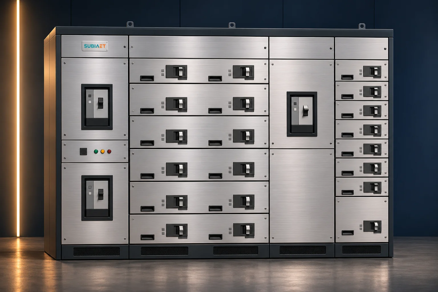
Form 2b, 3b and 4b describe which parts of a low-voltage power assembly are separated from one another, including busbars, functional units and external conductor terminals. The letter identifies a variant within each numbered form.
It is a statement about geometry, made of partitions, covers, shrouds and device housings. It is not a statement about voltage, isolation, the ingress protection of the enclosure as a whole, or internal arc performance. Use the designation to check the physical arrangement. Verify the actual electrical and access conditions separately for each task.
Compare adjacent feeders F1 and F2, with F3 sharing the same assembly in the worked example. Hold the electrical duty fixed while comparing four physical objects.
Use the legend and section detail to identify what each line represents, such as a partition, shroud or another form of barrier. It does not assert anything about potential. A partition between F1 and F2 means there is metal or insulation in that plane; it does not mean F2 is dead, and it does not mean F1 is isolated. The EAE engineering guide illustrates how partitions, insulation and suitable device housings can contribute to the specified separation. Verify the offered method and applicable evidence. So “Form 3b” does not by itself tell you that there is a steel wall — it tells you which objects are kept apart, and leaves the method to the manufacturer’s design and to the drawing you are given.
For example, a feeder may have a breaker in the front, its load-side terminal set at the rear and a cable that enters from below. Those are three physical locations for one circuit. Mark the same feeder identifier across the single-line, front view and section so that the drawing review follows the same circuit throughout.
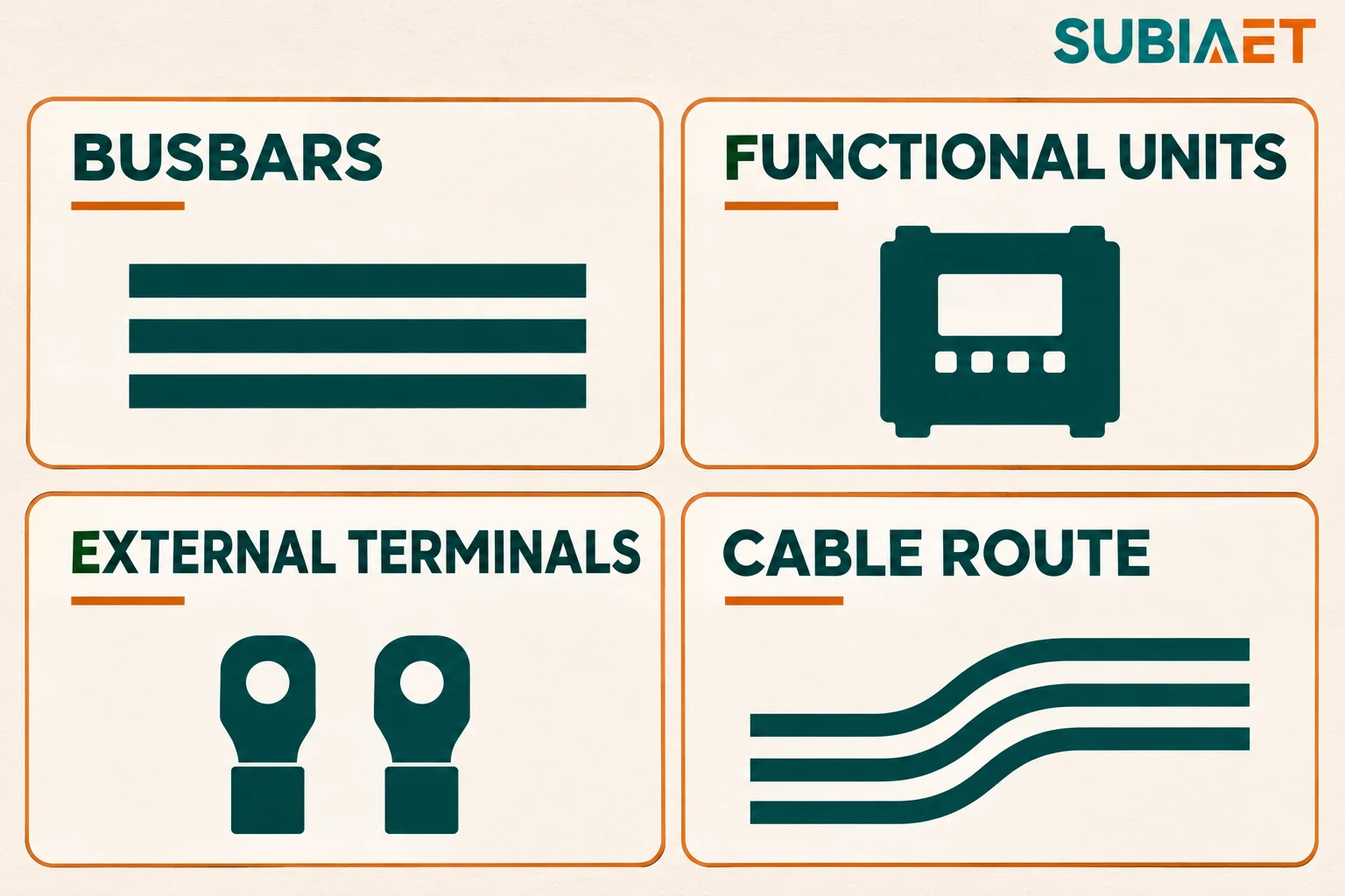
Form 2b draws one boundary: the busbar zone is separated from the functional units and from the external conductor terminals. The ABB separation diagrams illustrate this boundary. The designation does not require functional-unit-to-unit separation and does not require individual terminal spaces.
Picture an assembly with one incomer, one busbar run and three outgoing feeders. In fictional Offer A, the busbar sits behind a barrier, and the three feeder units and their three terminal sets use common access. Reaching F1’s terminals in this layout would involve a cover that also exposes F2’s and F3’s terminals. The F1 breaker sits beside the F2 breaker without a unit partition in this example.
The busbar is common to multiple feeders. Opening one feeder does not by itself isolate that busbar. The barrier separates the busbars physically, and the approved work plan establishes their electrical state. The outgoing terminals, by contrast, can be made dead as part of a task when the authorised team addresses all applicable sources. A designer may reasonably decide that a common terminal area is an acceptable arrangement for the duty in question, subject to the owner’s task and the verified design.
For a buyer, the practical consequence is to check the terminal access drawing. In this offer, a task at an outgoing terminal set is a task in a shared space. If the site’s method for that task assumes a boundary around one feeder’s terminals, the submitted drawing does not demonstrate it. Check whether any additional protection lets adjacent covers stay in place.
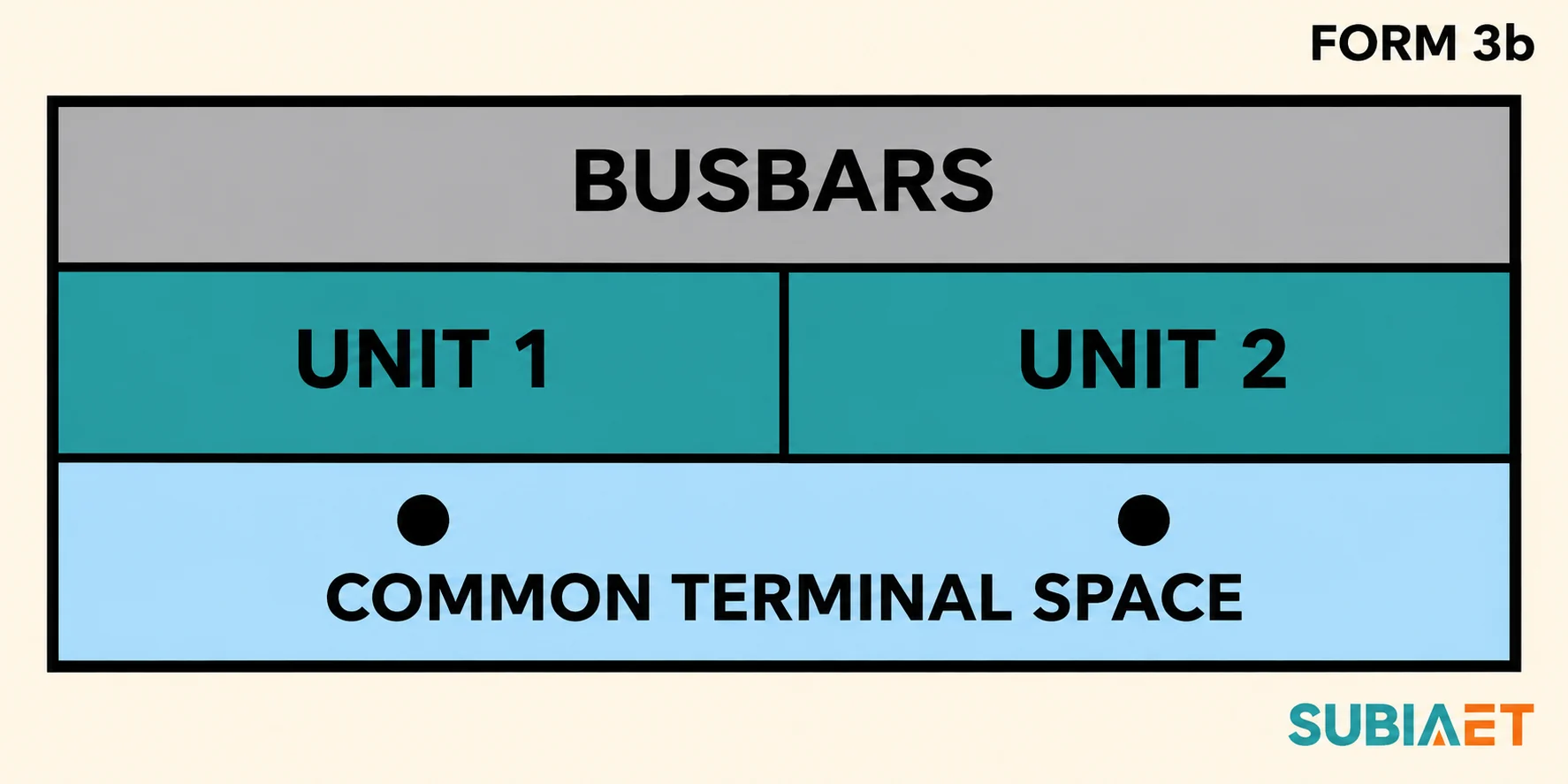
Form 3b draws three boundaries. The busbar zone is separated. The functional units are separated from one another. The external conductor terminals and external conductors are placed outside the functional units and away from the busbars. What it does not require is that the terminal sets be separated from each other: the terminals for F1, F2 and F3 may sit together in one common zone.
In fictional Offer B, barriers separate the feeder units. The vendor shows one terminal bay behind a cover shared by F1, F2 and F3. This is one way to implement the form. Other constructions may use different barriers or covers.
This is the distinction that catches people, because the front elevation looks convincingly compartmented. The compartments they are looking at are the units. The terminals are below, behind, or above them, in a zone the front elevation may not show at all. A partition between the units establishes a boundary in the device area. Follow the drawing into the terminal zone to see what protects the adjacent terminal sets and which covers serve them.
The letter identifies a variant within each form. For 2b and 3b, check the relationship to the busbars. For 4a and 4b, check where the terminals sit relative to their own functional unit. The IEC 61439-2:2020 contents preview lists Table 104 and the illustrations in informative Annex BB. Read the row for the exact designation in the edition your project applies, then read the manufacturer’s drawing — the label alone is a shorthand, not an installation description.
In the drawing below, the busbar zone and unit boundaries are continuous, while both terminal sets are shown in the same lower space. This is a conceptual section. The actual terminal zone may sit behind or beside the units, and the cover layout is still an evidence question.
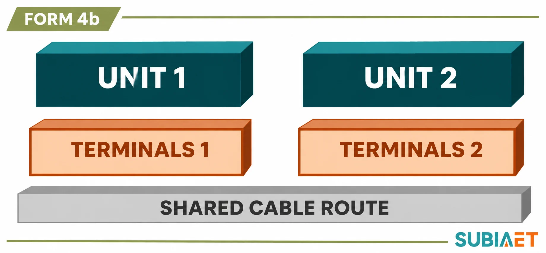
Form 4b retains separation between the busbars and functional units and between the functional units themselves. It also gives each terminal set its own protected space. Each functional unit’s external conductor terminals sit in an individual, separate, enclosed protected space that is outside and apart from the associated unit, separated from other units’ terminals and from the busbars.
Contrast that with the 4a variant, where the terminals for external conductors are located in the same compartment as the associated functional unit. Form 4a also separates terminal sets from those of other units. Its own terminal set sits within the associated functional-unit compartment. In 4b, its own set is in a separate protected space. Ask how that space is accessed on the offered board.
What 4b does not require is a private duct for every cable. The base Form 4 requirement distinguishes external conductors from the busbars and from other functional units and their terminals; it does not require external conductors to be separated from each other. A shared alley or glanding zone can be compatible where the actual conductor route and barriers maintain the required separations. Verify the entry and route against the specified cable sizes, bends, glands and usable space.
The historical UK construction descriptions illustrate the range well, and they also show why the designation needs reading rather than guessing. The July 2011 BEAMA guide describes UK Types 4 to 7 within Form 4b, including common glanding in some arrangements and integral glanding per circuit in the pictured Type 7. Type 7 is a UK construction description with its own glanding arrangement; it is not an IEC designation and should not be exported as one. That guide also belongs to the older edition — its Annex AA numbering is the numbering of that time, whereas in IEC 61439-2:2020 Annex AA is now the set of user/manufacturer agreement items and the form illustrations are Annex BB. Use the guide for the physical relationships and the materials question, not as current clause text.
Trace F1 on the submitted section and access drawings from its gland to its terminal. Verify which covers the approved inspection or work scope would involve. If the proposed access also removes the protection over F2 and F3, the drawings do not demonstrate the example’s F1-only physical access requirement.
Where a circuit has an associated neutral, show its terminal location and the parts that remain connected under the relevant condition. Map the protective conductor and control terminals separately. For a project that names a national type or a specific gland arrangement, ask the supplier to show that detail on the same section.
IPXXB appears in this discussion because the IEC 61439-2:2020 synopsis identifies at least IPXXB for parts within the functional-unit compartment that remain live when the unit is switched off, for forms higher than 1. Verify the applicable access conditions in the project’s agreed specification. It is a contact-protection statement about hazardous parts inside a compartment, in a defined state, and it is one of the areas the third edition clarified.
The additional letter B concerns finger access to hazardous parts under the defined test conditions. The two X characters leave the solid-object and water numerals unspecified. Ask for the separately declared enclosure protection and the states that declaration covers.
The engineering reason for the rule is worth understanding, because it explains why the condition is stated the way it is. A feeder that is switched off is not a feeder with nothing live inside it. The incoming side of its device, the busbar tap feeding it, control and auxiliary supplies, and any backfeed from the load side can all remain energised. The separation arrangement shows which boundaries are present. IPXXB describes the applicable protection against access to hazardous parts, which may be provided by barriers, insulation or another verified method. The cited EAE explanation of §8.101 discusses normal access with a door or cover open or removed, unless otherwise agreed between manufacturer and user. Confirm the stated access condition and any agreement.
A useful drawing review distinguishes the assembled condition from the stated service access condition. For a removable unit, ask which shutters or covers remain in place, which parts of the compartment may remain live, and which verification record applies to that state. For a fixed unit, identify the cover involved in the nominated task and the barrier that remains between the access area and other live parts.
Ask about the following as separate items, because they are separate claims:
A barrier is a mechanical and dielectric object. It does not de-energise anything, and it does not create an isolating function. The following are all separate questions, and a form label answers none of them.
Isolation. Whether the assembly provides a suitable isolating function for a given circuit, in a given position, is a design question about disconnectors and device configuration — not about partitions. Identify every credible source and stored-energy condition for the defined boundary. These can include the incoming supply, a parallel path, auxiliaries, stored energy and backfeed. The site’s authorised team applies the relevant verification and work controls. A barrier between you and the neighbouring feeder is not evidence that the neighbouring feeder is isolated, and it is certainly not evidence that your own feeder is.
Authorisation and task boundaries. The UK Health and Safety Executive’s HSG85 guidance treats the decision to work on dead equipment, and the separate and tightly controlled decision to work on or near live conductors, as matters of task-specific assessment and competence. It also makes a point that maps directly onto this article: when you work on a de-energised circuit, adjacent energised parts still require consideration. That is a work-planning statement, not a product property, and its legal framing is jurisdiction-specific — the principle travels, the regulations do not. No form of separation authorises a task, and a Form 4b label is not a permit.
Internal arc fault performance. A form designation says nothing about what happens inside the assembly during an arcing fault. Where arc performance is specified for a project, request evidence on the agreed basis. IEC TS 61641:2026 is the current IEC technical specification for LV assembly internal arc-fault protection and replaces IEC TR 61641:2014 and IEC TS 63107:2020. Confirm applicability where the contract cites earlier evidence. Its scope covers distinct verification approaches aimed at personnel injury risk, damage, and power availability after an event, including passive measures, active mitigation, and arc-ignition-protected zones; it also states that maintenance conditions and personal protective equipment fall outside its scope. When you ask for evidence, ask for the applicable assembly or zone, the criteria applied, the configuration tested, the accessible sides, the current and duration, the door and closure state, and the protective device and mitigation conditions assumed.
Two errors to avoid here. First, do not transfer a medium-voltage internal arc classification onto a low-voltage form label: an IAC class belongs to medium-voltage switchgear classification and testing, and a form of separation is a different object of description at a different voltage level. Second, do not treat contact protection as an arc test. IPXXB and an arc-fault verification answer different questions about different events.
Ratings and verification of the assembly itself. Review assembly characteristics such as short-circuit withstand, temperature rise and enclosure protection under the relevant assembly requirements. The IEC 61439-1 synopsis identifies the general rules to use with the relevant product part. Check the project’s protection coordination separately for its network and devices. A form of separation does not prove the ratings, the verification status, or the suitability of the proposed assembly for your duty. It describes one aspect of its construction.
Here is a worked comparison. A hypothetical industrial power switchgear and controlgear assembly has one incomer, one busbar and three protected outgoing feeders F1–F3. All three bids are for the same service voltage and frequency, the same load and fault duty, the same protection and selectivity study, the same cable types and entry direction, the same access side, the same room limits, and the same installation conditions.
One nominated task concerns the F1 external conductor terminal set. The owner states the requirement as a physical one: reach that terminal set through its own boundary without removing the covers that protect the F2 and F3 terminal sets. The site’s approved electrical isolation and outage plan is a separate decision made elsewhere, and nothing in this comparison assumes which circuits remain energised while work takes place.
| Offer | What the submitted drawing separates | Reaching F1’s terminals in the offered layout | Status against the F1-only requirement |
|---|---|---|---|
| A — Form 2b | Busbar zone separated from the functional units and the external conductor terminals. No unit-to-unit separation and no individual protected terminal space. | Opens a shared service space for the feeder equipment or terminal access, giving access to F1, F2 and F3 terminals together. | Does not meet the stated requirement. May suit the same duty if common terminal access is acceptable and the offer demonstrates the remaining requirements. |
| B — Form 3b | F1–F3 functional units separated from one another; external conductor terminals and conductors outside the units and away from the busbar zone. Terminal sets share one bay. | The unit partition is real, but access to F1’s terminals means removing the single cover over the common terminal bay, exposing F2 and F3 with it. | Does not meet the stated requirement. The additional unit segregation does not independently protect neighbouring terminal sets during access in this drawing. |
| C — Form 4b | Individual enclosed protected spaces for the F1, F2 and F3 terminal sets, separate from the associated functional units. | Intended to reach the F1 terminal set through its own boundary with the F2 and F3 covers left in place. A shared cable alley is possible if its actual route preserves the required boundaries. | Candidate, conditional. It meets the physical requirement only if the drawing shows the access route as proposed, the usable cable and bending space supports it, and the barriers are verified in the as-supplied arrangement. |
What this comparison establishes is narrow and useful: the F1-only physical access requirement distinguishes these three specific proposals. It does not rank the manufacturers, and it does not say that 4b is better equipment. Offer A and Offer B remain candidates if the owner accepts common terminal access and the remaining electrical, installation and verification requirements are met.
What the comparison does not establish is equally important. Actual availability depends on the sources, bus arrangement, isolation extent and approved task. The three bids describe physical access for comparison. Offer C’s label does not shorten an isolation programme, does not decide which circuits are live, and does not remove the need for valid as-configured evidence that the delivered board matches the drawing that won the evaluation. The remaining open items for C are the ones worth writing into the purchase order: the section drawing through the F1 terminal pocket, the cover fixing and tool requirement, the usable cable bending and gland space behind the shared alley, and the verification record for the barrier as installed.
The documents should let you trace each boundary. Use consistent object identifiers on the general arrangement (GA), section drawings and terminal schedule.
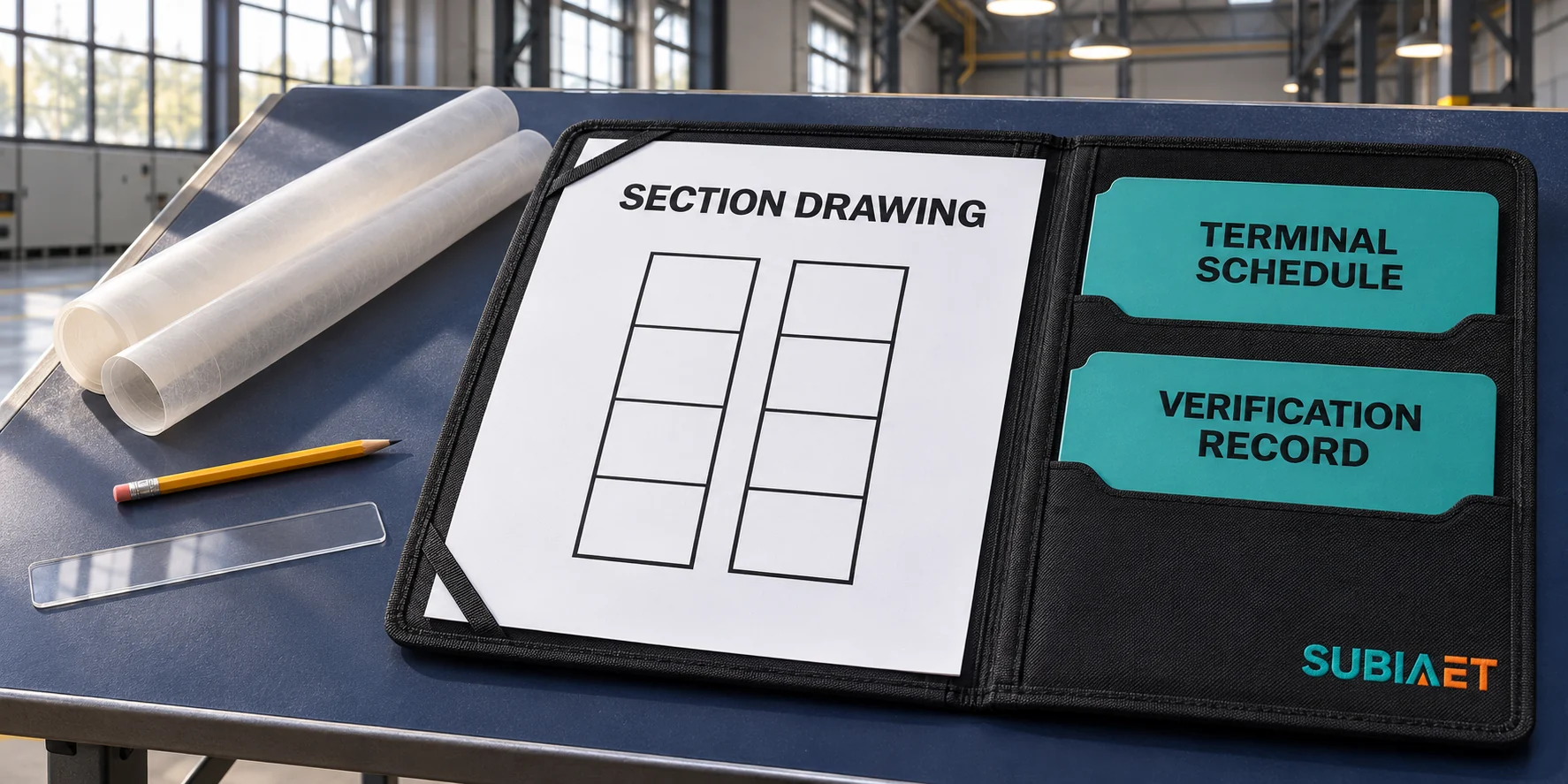
The industrial distribution application and LV switchgear overview provide project and equipment context. See switchgear functions for device roles and fixed vs withdrawable MV switchgear for a separate example of task-specific access and outage review.
No. Form 4b describes an individual, enclosed protected terminal space for each unit’s terminal set, separate from the associated functional unit and from other units’ terminals and the busbars. That is a construction property. Whether you may work at F1’s terminals at all, and under what conditions, is decided by the site’s isolation and work-permit regime, which must account for every source including backfeed, and by the task-specific assessment that goes with it. The separation may reduce what is exposed when a cover is opened; it does not authorise opening it.
No, and the two are tested differently. The IP rating of the enclosure is a whole-assembly property describing protection against solid foreign objects and water under stated conditions. IPXXB, in the form-of-separation context, is a finger-access statement about hazardous parts remaining live inside a functional unit’s compartment after that unit is switched off, applying to forms above 1 and expressed with the two characteristic numerals left unspecified. Check the two declarations separately. Confirm the access conditions for the specified unit, including the relevant doors and covers.
Do not assume it does from the designation alone. In the comparison published by manufacturers for Form 3b, the functional units are separated from one another and the external conductor terminals and conductors are placed outside the units and away from the busbars, but the terminal sets themselves are not required to be individually enclosed — a grouped terminal area is consistent with 3b. The suffix alone does not establish which terminal sets share a space on the proposed board. Read the exact form in the governing edition and confirm the actual boundary on the manufacturer’s section drawing. That is why a section through the terminal zone, not the front elevation, is the document to insist on.
They are related but not interchangeable labels. The July 2011 BEAMA guide describes UK construction Types within Form 4b, with Types 4 to 7 as alternative constructions including common glanding chambers in some variants and per-circuit integral glanding for the pictured Type 7. Those are construction descriptions from a historical national guide, not IEC designations, and they should not be exported as such. In the current IEC structure, the form illustrations are in informative Annex BB under 8.101 and Annex AA holds the user/manufacturer agreement items — a different numbering from the older guide. If a project specifies a UK Type, get the drawing that shows what that type means for the offered board.
Yes. Evaluate the actual offered layout against the task. Form 2b separates the busbars from units and external conductor terminals. In Offer A, the units or terminals share access and the owner would have to accept that arrangement. If the job requires access to F1 with F2 and F3 protected by their own retained covers, specify that physical boundary and ask each bidder to show it. The site’s electrical isolation and work approval are separate.
