Request a Quote
Share the equipment and project requirements. If you need help selecting a model, describe the application.
Have drawings or specifications? Email [email protected] with your project reference.

A transformer vector group is a compact statement about two things at once: how each three-phase winding is connected, and how the low-voltage phasors sit relative to the high-voltage phasors. It is written as a short code on the nameplate — Dyn11, Yyn0, YNd11, YNyn0 — and it is read left to right in high-voltage/low-voltage order, regardless of which way power actually flows through the unit.
That single line of code answers a surprising number of practical questions. It tells a designer whether a neutral terminal exists on the low-voltage side, which winding connections need to be considered in a zero-sequence study, and whether two units can sit on the same bus without a standing phase angle between them. It does not tell you the transformer’s impedance, its earthing arrangement, its tap range, or whether the protection scheme has been set up for it. Keeping those boundaries straight is what separates a useful reading of the code from an expensive misreading of it.
The letters come first because they describe physical connections, and the connections constrain everything the number can mean.
Uppercase letters refer to the higher-voltage winding and lowercase letters to the lower-voltage winding. D/d means delta, Y/y means star or wye, and Z/z means zigzag. A suffix N/n means the neutral point of that winding is brought out to a terminal. The order is fixed by winding voltage, not by energy direction: a generator step-up transformer that feeds power from the LV side into the HV side is still written with the HV winding first. Schneider Electric’s winding notation guide explains these letters.
| Symbol | HV / LV connection | Neutral brought out |
|---|---|---|
| Dyn11 | Delta / star | LV only (n) |
| Yyn0 | Star / star | LV only (n) |
| YNyn0 | Star / star | Both (N and n) |
| YNd11 | Star / delta | HV only (N) |
Decoding the two symbols in this article side by side:
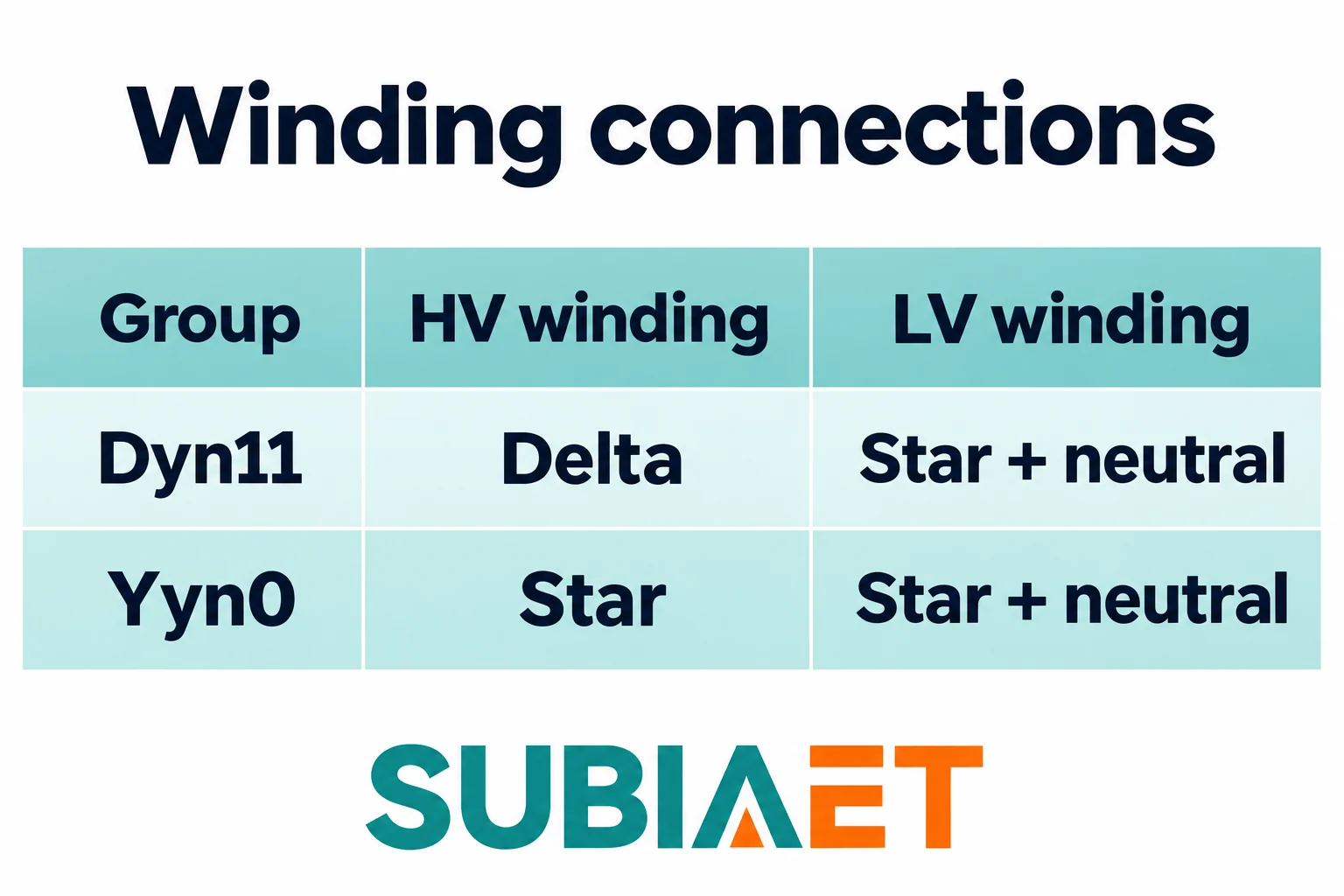
That last point is where a lot of reading goes wrong. Both codes contain an “n”, and it is easy to assume the letter describes the transformer as a whole rather than one specific winding. It does not. In Yyn0 the neutral is available on the LV side only; the HV star point exists electrically inside the transformer but is not presented as a terminal for connection. YNyn0 is a different transformer from the system’s point of view, because it offers both neutral terminals and therefore different possibilities for how the HV side is referenced.
The clock number is the second half of the statement, and it only becomes meaningful once the letters are settled. A delta winding has no physical neutral point, so any phase-to-neutral reference on that side has to be constructed rather than measured at a terminal. The standard convention handles this by allowing a fictitious neutral for the purpose of stating phase displacement. That fictitious neutral is a reference for the phasor diagram; it is not an accessible terminal, and nothing should be connected to it.
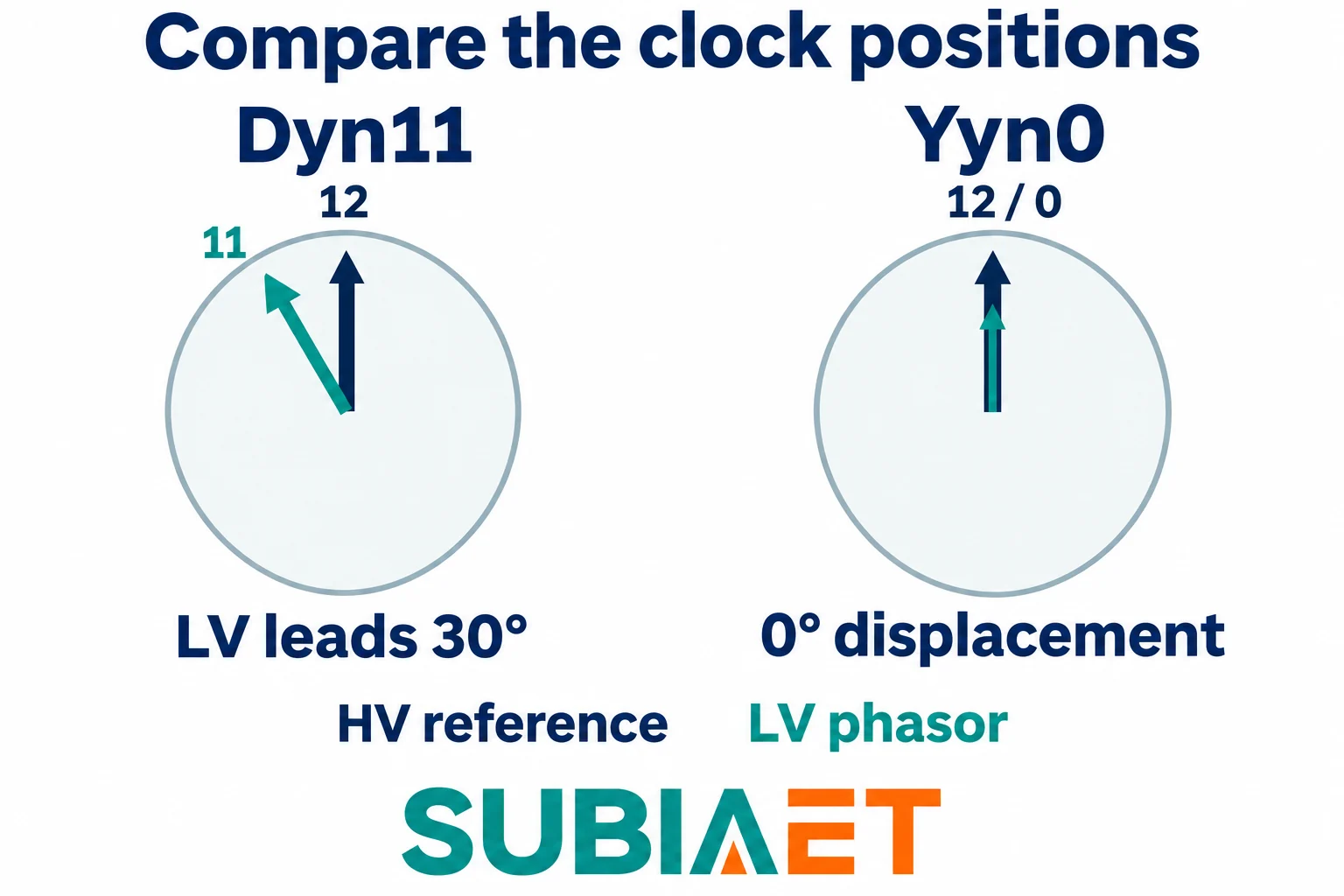
To compare two vector groups honestly, both have to be drawn on the same reference. The convention used in IEC 60076-1 for phase displacement is: take corresponding terminal-to-neutral phasors on each side, using a real neutral where one exists and a fictitious one where it does not, apply positive phase sequence to the HV terminals, and let the phasors rotate counterclockwise. The HV phasor is placed at 12 o’clock. The clock number of the LV phasor is then read off the same dial, and increasing clock numbers correspond to increasing LV lag. See the IEC definition reproduced by GSO.
Under that convention:
Two cautions about reading these dials.
First, the comparison is between directions, not lengths. A clock diagram is a statement about angle. Read the rated terminal voltages and ratio data separately for magnitude, keeping line-to-line and winding-voltage quantities distinct. The dial uses directions to make the angle clear; its arrow lengths are not a voltage-ratio calculation. A vector group supplies connection and phase information, while the actual voltage ratings are separate nameplate quantities.
Second, “lead” and “lag” describe phasor rotation, not current. A vector group says nothing about the phase angle between voltage and current, nothing about power factor, and nothing about which side is the source at any given moment. It is a relationship between two sets of voltages defined by the winding geometry.
The practical consequence of putting those two diagrams next to each other is simple: between a Dyn11 LV side and a Yyn0 LV side, both referred to the same HV reference, there is a 30° angular difference. That single fact drives most of the compatibility discussion that follows.
The lowercase n is a statement about hardware. It says the LV star point is brought out to a terminal that a cable can be landed on. It does not say the terminal is earthed, does not say what the earthing impedance is, and does not say the neutral is sized for the current any particular load will return through it.
Three distinct things are being conflated whenever this gets blurred:
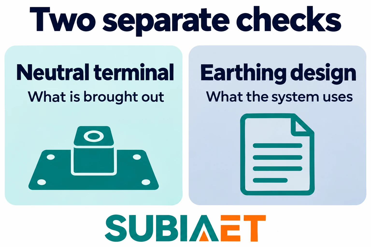
For a project where line-to-neutral loads are expected on the LV side, the neutral terminal is a precondition but not the answer. The design still has to establish that a neutral conductor is actually carried to the loads, that the terminal and conductor are rated for the neutral current the load mix will produce, and that the unbalance the installation will see is acceptable. Schneider Electric’s system earthing guide shows how winding connections and system earthing fit together. A four-wire distribution system fed from a transformer with an accessible neutral is a coherent design; the same transformer with no neutral conductor run to the load is not, no matter what the nameplate says.
Ground-fault behaviour is a further step away. The zero-sequence impedance of a transformer depends on the winding group and on the magnetic construction, and the fault current that flows in a real installation depends additionally on how the connected system is earthed on both sides. A closed delta winding can provide an internal circulating path for zero-sequence components, but that is different from a zero-sequence line-current path through its three external terminals — but the magnitude of any earth-fault current, and the division of it between paths, is a network calculation that needs the actual transformer data and the actual system earthing. The group on its own does not set zero-sequence impedance or establish the neutral current capability of the winding. See ABB’s distribution handbook for the influence of winding connections and magnetic construction.
For replacement work there is one more place the vector group surfaces: transformer differential protection. A differential scheme for a two-winding transformer may compensate for the phase displacement introduced by the winding group, because the currents entering and leaving the unit appear shifted by that same angle. When a unit is replaced, the relay method actually in use, the transformer data and the current transformer data all have to be checked against what the new unit presents. A protection scheme commissioned for one vector group is not automatically correct for another. ABB’s relay manual provides an example of vector-group compensation.
Consider a concrete case. A plant has an existing Dyn11 distribution transformer supplying an LV board. A second unit is proposed to share the load at the same LV bus, and the proposal is a Yyn0 transformer of the same kVA and the same nominal voltage ratio, fed from the same HV phase sequence, with the conventional terminal correspondence between HV and LV designations.
On paper the two units look interchangeable. Both have the same specified line-to-line voltage ratings and kVA; both bring out an LV neutral. These matching terminal-voltage ratings do not mean that the individual coil turns ratios are identical for different winding connections. The vector group is the one line on the nameplate that differs — and it is decisive. Referred to the same HV reference, the existing LV side sits at clock 11 and the proposed unit’s LV side sits at clock 0. That is a 30° displacement between the two LV sides. Before the intended bus coupling is closed, corresponding LV terminal voltages would differ in phase by 30°. They are therefore unsuitable for direct parallel connection in this stated arrangement. Matching kVA and matching nominal voltage do not remove that difference, because neither of them is a statement about angle.
That is the bounded conclusion, and it is enough for the review: the two units are not directly compatible at the intended common bus under those stated conditions. What follows from it is a design decision — revisit the specification, reconsider the winding arrangement, or revisit the bus arrangement — not a switching procedure. Nothing here should be read as a method for tying two transformers together; that is an engineering and operational decision made against the actual installation.
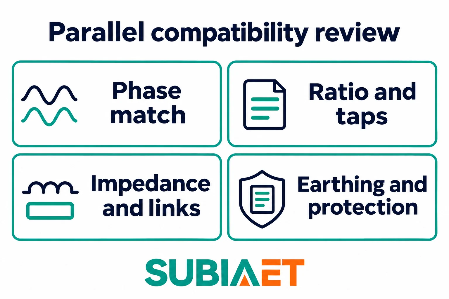
The more common and more subtle failure is the opposite one: assuming that a matching vector group settles the question. It does not. For two Dyn11 candidates under the same reference assumptions, the code no longer introduces that 30° difference, but the actual phasing and the other compatibility conditions still require verification.
Schneider Electric’s parallel operation guide lists the characteristics to compare.
For the wider picture on how nameplate data, impedance and selection decisions fit together, the published material on reading a transformer nameplate, selecting a distribution transformer for an industrial project and percent impedance in fault-current and voltage-drop studies covers the surrounding quantities. The transformer families overview shows the product range those decisions are applied to. If you are preparing a replacement or a parallel review, the vector group is the right starting line — just make sure the other four lines of enquiry are on the list too.
Clock 11 counts 330° of lag from the HV reference. A full turn is 360°, so the same LV direction is 30° ahead of the reference.
It means the LV star point is brought out to a neutral terminal. Check the drawings and ratings for the earthing arrangement and how the neutral can be used.
Both have star windings and zero phase displacement. The capital N in YNyn0 indicates that the HV neutral is brought out as well as the LV neutral.
Confirm phase sequence and terminal correspondence, ratio and taps, impedance and load sharing, and the earthing and protection design for the intended common bus.
