Request a Quote
Share the equipment and project requirements. If you need help selecting a model, describe the application.
Have drawings or specifications? Email [email protected] with your project reference.

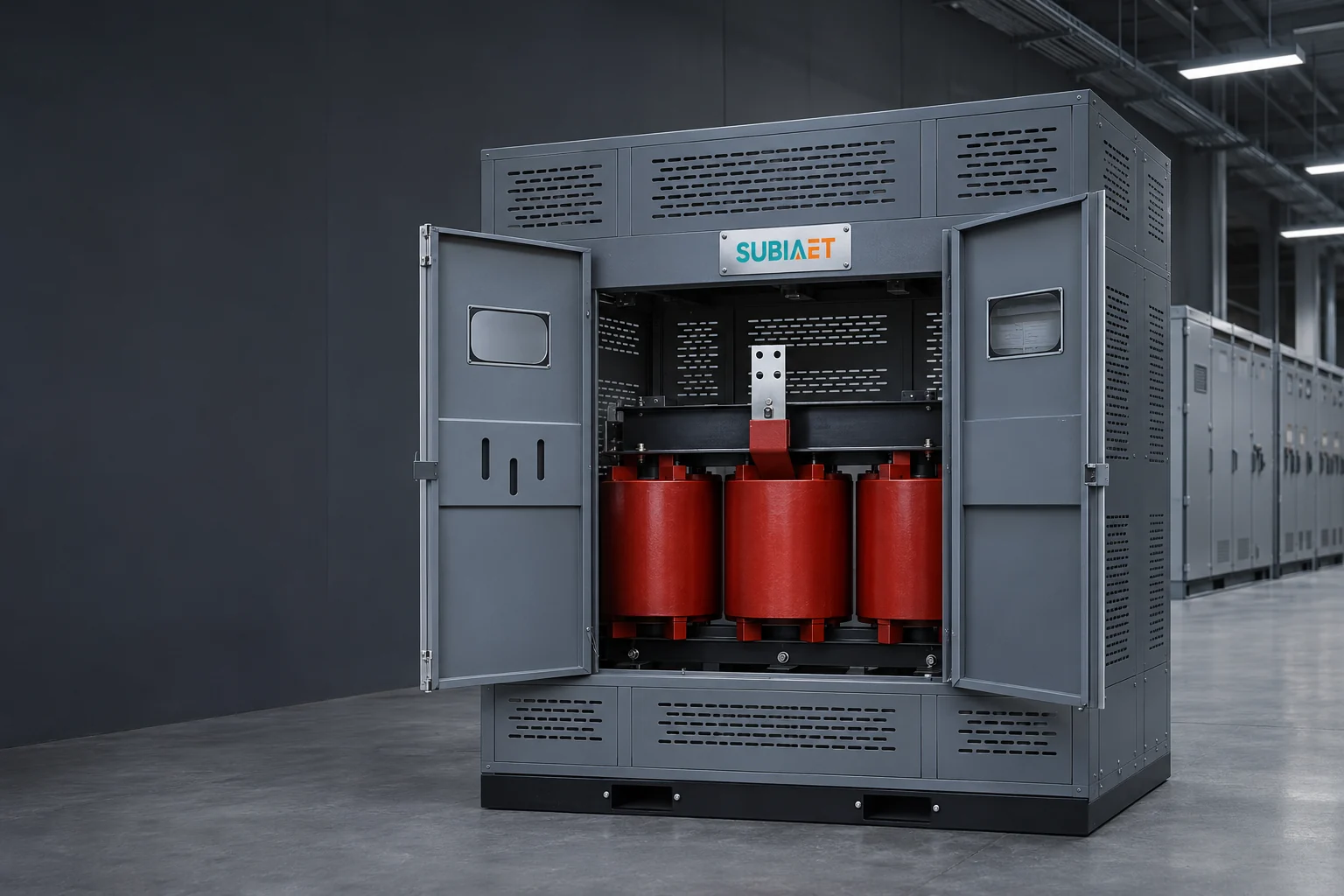
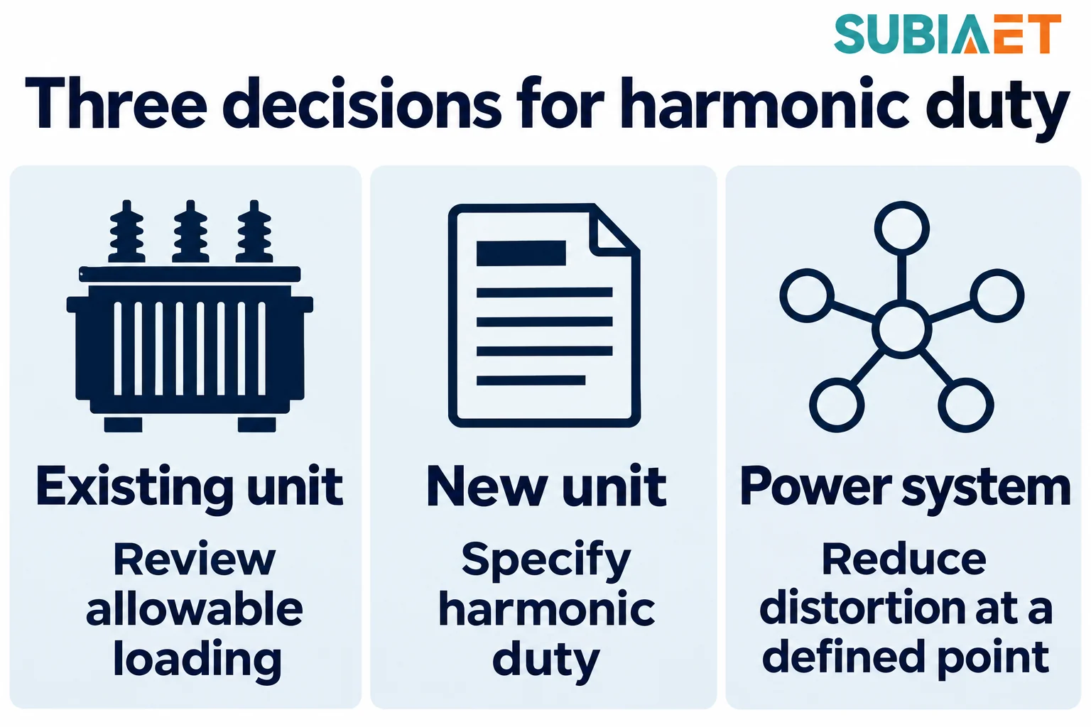
A transformer supplying distorted current is not automatically overloaded, and it is not automatically fine. A useful review needs the harmonic spectrum, the unit’s loss characteristics, the operating profile and the actual cooling conditions. The decision can then follow one of three tracks: assess allowable loading on an existing unit, specify a new unit for the duty, or reduce distortion at a defined point in the system. Keep those questions separate so that a thermal-capacity decision is not mistaken for a filtering result.
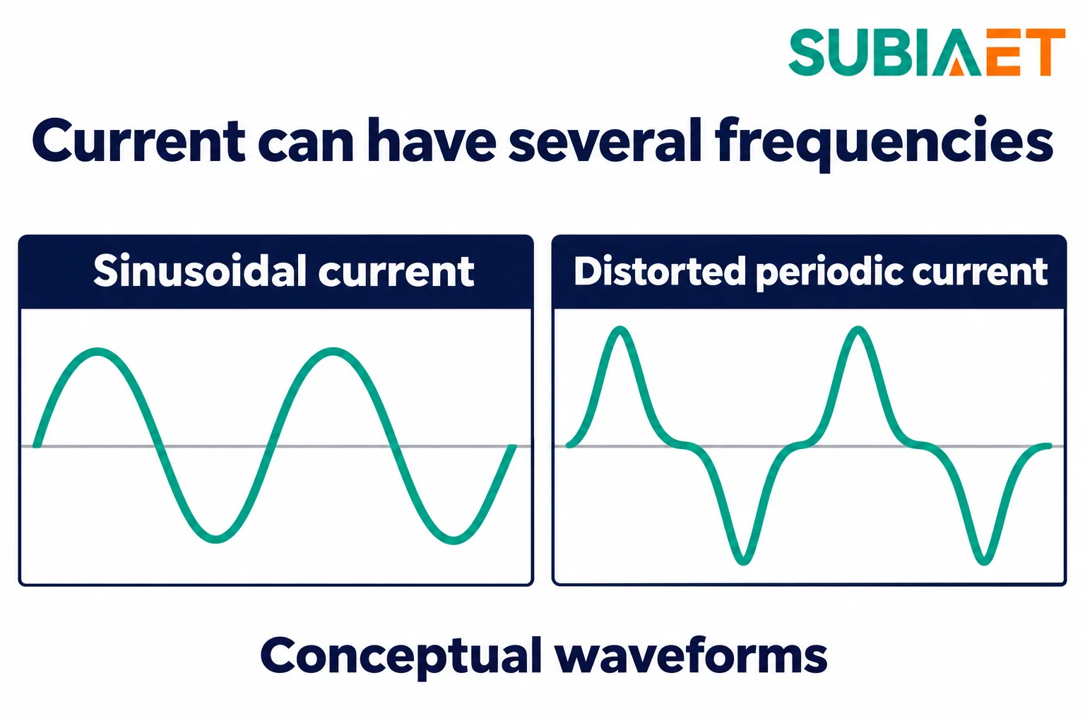
A harmonic is a sinusoidal component at an integer multiple of the fundamental frequency. If the fundamental is 50 Hz, the fifth harmonic is 250 Hz, the eleventh is 550 Hz, and the order h is simply that multiplier. A distorted periodic current is the fundamental plus some set of these components, each with its own amplitude and phase. The winding carries the sum, so the sum is what heats it.
Two numbers describe the sum, and they are easy to confuse.
The total RMS current is the root-sum-square of every component, fundamental included:
I_rms = √(Σ I_h²), including the fundamental h = 1 and all harmonic orders present
Current total harmonic distortion is the RMS of the harmonic components alone, expressed against the fundamental:
THDi = √(Σ I_h² for h ≥ 2) / I₁ × 100%
THDi is a ratio to the fundamental, not to the total. A 20% THDi on a 100 A fundamental and a 20% THDi on a 400 A fundamental describe very different amounts of harmonic current, and the same THDi can be built from entirely different orders. That single number is useful as a screening label and incomplete as a thermal description. The Schneider Electric installation guide gives the relationship between RMS current, the fundamental and THDi.
Current distortion and voltage distortion are separate measurements. Nonlinear equipment can draw distorted current, but its spectrum depends on the equipment, operating mode and supply conditions. Voltage distortion at the transformer terminals is also influenced by network impedance and other loads. Low voltage distortion does not establish that the transformer current is sinusoidal. Record voltage and current distortion separately, at a stated location, rather than treating one as a substitute for the other.
Drives, rectifiers, UPS units and battery chargers are reasons to investigate the duty, not proof of a particular spectrum. Input-stage design, filtering, loading level and the mix of loads on the same busbar can all affect the result. Two plants with similar equipment nameplates may present different spectra at the transformer. Use actual line-side measurements or vendor data for credible operating modes rather than assigning a fixed harmonic pattern to every device in a broad category.
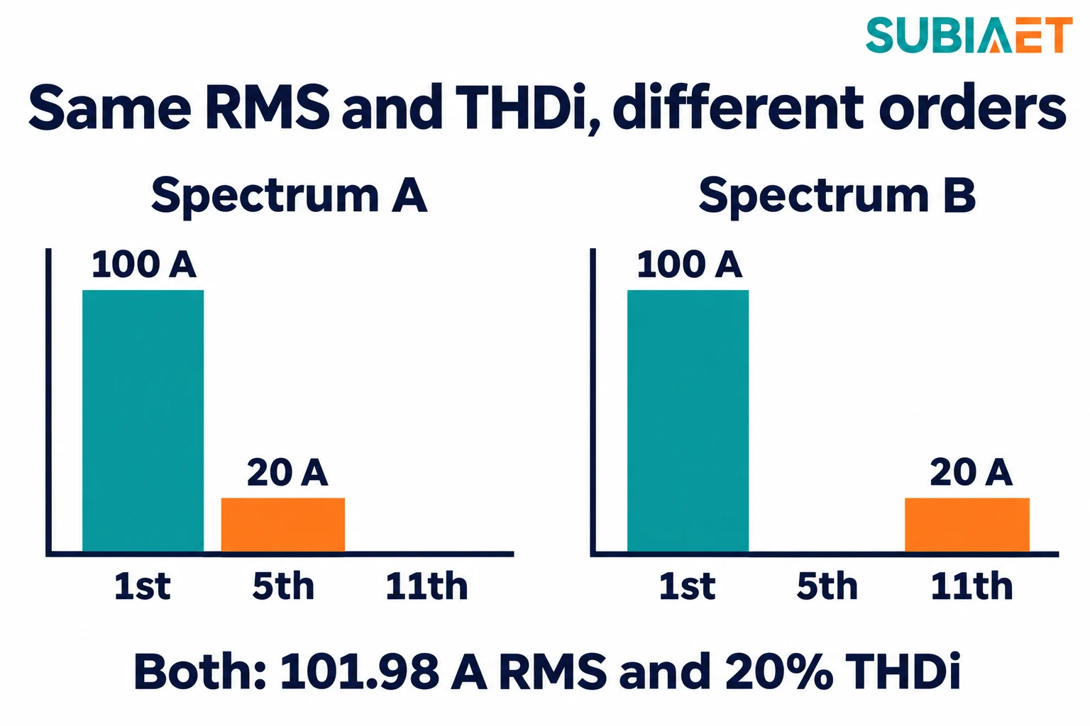
At the same total RMS and the same winding DC resistance, the basic I²R term is the same. The RMS value already includes the harmonic content, so the copper loss associated with DC resistance does not change when you redistribute that same RMS current across different orders.
Other losses can respond differently to frequency. Leakage flux induces eddy currents in winding conductors, and a simplified winding-eddy model weights the square of each harmonic current by the square of its order, h². That is a weighting for one loss mechanism, not a general model of all transformer losses. Other stray losses have different frequency behavior, while voltage and frequency also matter to the core. The Eaton design guide illustrates why harmonic order matters for nonlinear-load duty.
The practical consequence: a transformer can carry the correct RMS current and still run hotter than expected if a large share of that RMS sits in high orders. That is the whole reason a harmonic-duty review exists. It is a check on losses and allowable thermal duty under the actual spectrum and cooling conditions, rather than a judgment from waveform appearance alone.
In a three-phase four-wire system, triplen components — third, ninth, fifteenth — can add in the neutral conductor when the phase currents carry them in phase rather than cancelling. That is a neutral and winding loading issue, not a duplicate of the phase RMS reading. Where a neutral is present, record the actual neutral current and confirm the winding and conductor arrangement; a delta winding and a wye winding with a neutral brought out do not present the same internal duty. Do not carry a fixed neutral multiplier across systems; the harmonic magnitudes and phase relationships matter. Schneider Electric’s neutral-current illustration explains why neutral current needs a separate check.
A single THDi number or nonlinear-load percentage does not determine a universal derating factor. Use the spectrum, loading profile and thermal conditions, and investigate significant changes in duty or unexplained heating.
Two invented spectra make the point precisely. Both are one-phase illustrations with all components other than those listed set to zero.
| Component | Spectrum A | Spectrum B |
|---|---|---|
| Fundamental (h = 1) | 100 A | 100 A |
| 5th harmonic | 20 A | 0 A |
| 11th harmonic | 0 A | 20 A |
| Total RMS | 101.98 A | 101.98 A |
| THDi | 20% | 20% |
The shared arithmetic:
Total RMS = √(100² + 20²) = √(10,000 + 400) = √10,400 ≈ 101.98 A
THDi      = 20 / 100 = 0.20 = 20%
Every headline number matches. Now apply a simplified order-squared weighting to the two spectra:
W = Σ(h² · I_h²) / Σ(I_h²)
The sum in the denominator includes the fundamental, so it equals the square of the actual total RMS — here 101.98² ≈ 10,400 A². It is normalized to the actual current in the example. The Schneider PowerLogic meter manual describes this normalization.
W_A = (1²·100² + 5²·20²) / (100² + 20²)
    = (10,000 + 25·400) / 10,400
    = (10,000 + 10,000) / 10,400
    = 20,000 / 10,400
    ≈ 1.92

W_B = (1²·100² + 11²·20²) / (100² + 20²)
    = (10,000 + 121·400) / 10,400
    = (10,000 + 48,400) / 10,400
    = 58,400 / 10,400
    ≈ 5.62
The ratio is about 2.9 to 1. The same RMS current, the same DC copper loss, and roughly three times the value of this winding-eddy weighting index, purely because the eleventh harmonic is weighted 121 times rather than 25 times for the same 20 A.
The weighting above compares one loss mechanism — the frequency-dependent winding-eddy component — across the two spectra. Use 1.92 and 5.62 only for that weighting comparison. They are not total losses in watts, temperature rises, allowable-load percentages or equipment K ratings. Establishing those outcomes requires the particular transformer and its operating conditions. If a K-rated unit is proposed, use the manufacturer’s specified rating framework and basis rather than assigning a product class from these illustrative numbers.
The index also assumes the h² behaviour applies to the dominant frequency-sensitive loss. Real transformers have other loss components with different frequency dependence, and a design with a different conductor form, transposition or flux-shielding approach will not respond identically. The comparison is a diagnostic for why the two loads differ, not a calculator that replaces the manufacturer’s thermal evaluation.
Normalization matters as much as the formula. Normalizing the same numerator against rated-current squared instead of actual total-RMS-current squared produces a different number with a different basis. State the basis every time, and never mix values from two bases in the same comparison.
The spectra have different winding-eddy weighting even though RMS and THDi match. That observation leads to three distinct engineering questions. The actual thermal result still requires the transformer’s design, loss distribution, loading and cooling conditions.
The question is concrete: with this measured spectrum, at this ambient temperature and this cooling arrangement, how much load can this transformer carry before its insulation reaches its temperature limits? The published scope of IEEE C57.110-2018 describes a recommended practice that addresses the assessment of existing liquid-immersed or dry-type transformers supplying nonsinusoidal current. That scope statement tells you the document is aimed at the right question; it does not supply a universal THDi threshold, and it does not by itself establish that any particular unit complies with anything.
The outcome of this track is a supported allowable load and its conditions. If it is below the required duty, compare limiting or redistributing load, changes to the system and replacement. The choice needs the actual capacity shortfall, operating constraints and project economics; unit age alone does not decide it.
When a unit is being purchased anyway, or the existing one cannot carry the duty, the review moves to specification. Here you provide the actual harmonic duty and the actual thermal conditions, and the manufacturer documents thermal capacity against them. A K-rated design, where that framework applies, is one way to state a thermal tolerance for nonlinear duty — in low-voltage dry-type practice it expresses the unit’s ability to tolerate additional heating from a nonlinear load under the rating conditions. It is not a filter, it does not remove harmonic current from the system, and it is not a substitute for matching the offered unit against your spectrum, your kVA, your neutral duty and your cooling. If a K-rated unit is proposed, ask what spectrum and what rating conditions the classification is stated against, and how the proposed unit’s thermal capability applies at the installation ambient, altitude and cooling conditions. Hammond Power Solutions’ K-rating explanation distinguishes harmonic-current tolerance from filtering.
The SUBIA oil-immersed and dry-type pages provide product-family context. They do not establish a specific harmonic-duty rating. State the actual spectrum and conditions in the enquiry, and ask what capability and evidence are available for the proposed configuration.
Mitigation acts on the system rather than simply increasing a transformer’s tolerance. Define the quantity to reduce, the measurement point and operating modes: for example, current distortion at a particular supply point, voltage distortion at a sensitive board, or neutral current in a four-wire system. Phase-shifting arrangements and filters can address selected harmonics under their design conditions. Eaton’s mitigation comparison distinguishes these measures from thermal-capacity approaches.
Effectiveness is configuration-dependent. A phase-shifting arrangement depends on the connected load groups and their harmonic behavior; cancellation may differ when their loading or input stages differ from the design assumptions. Filters require analysis of the impedance seen at their point of connection and a measurement point that establishes whether the intended reduction was achieved — an untuned or badly placed filter can create a resonance the system did not previously have. Published performance figures for any mitigation product are not predictions of your savings.
The tradeoff between allowable loading and mitigation is project-specific. Limiting a transformer’s load gives up usable capacity and may require operating or distribution changes. Mitigation adds equipment and must be assessed against its intended reduction target and the network. Neither approach automatically establishes the other result: a reduction in a measured distortion quantity still needs to be related to the actual transformer duty. Compare these options with a suitably specified replacement where that is part of the project.
An engineering review is only as good as the data behind it. Existing-unit and new-unit assessments both need the spectrum, but they need different supporting information. Schneider Electric’s guide to harmonic measurement describes measurement quantities and locations.
Do not add THDi percentages together across loads. THD is a ratio, and combining two ratios numerically produces a figure with no physical meaning; combine components by order using the relevant phase-angle information or stated engineering assumptions before recomputing the ratio. Adding per-order magnitudes without considering phase relationships is not generally the same as the resulting spectrum. The same caution applies to scaling a measured spectrum by an assumed load factor — state the assumption, and let the manufacturer see it.
A factory expansion loading workflow is the natural place to gather this, and the underlying kVA and current relationships are worth revisiting before any spectrum is converted into a loading percentage. If the choice of installation type is still open, the oil-immersed versus dry-type comparison covers how the cooling and siting decision interacts with thermal headroom, and the wider industrial selection workflow places the harmonic review among the other sizing inputs.
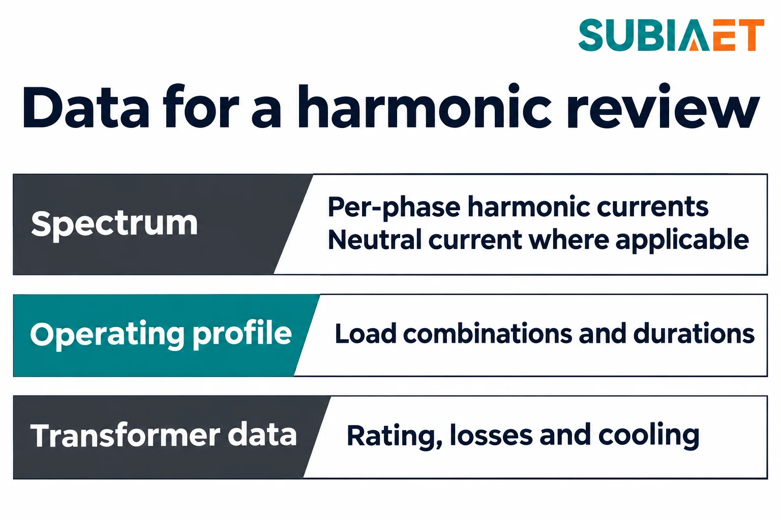
Watch for signals rather than thresholds: a substantial addition of nonlinear load to an existing transformer, sustained heavy loading on a distorted supply, uneven phase currents or a neutral carrying more than expected, and heating that the existing load and ambient do not explain. Recorded thermal trips, unusual heating or other electrical-system symptoms call for investigation of their causes. They are not proof that harmonics alone caused the problem.
If mitigation is part of the answer, specify it as its own requirement: the harmonic order or orders to be reduced, the point in the network where the reduction must be demonstrated, and the operating modes in which it must hold. Keep that requirement separate from the transformer’s thermal requirement, because a thermal rating alone does not establish the required distortion reduction, even when a proposed design combines more than one function.
Send the measured or expected spectrum, the operating profile and the existing unit data together, and describe the decision you are trying to make — allowable loading today, a new unit for a known duty, or a reduction target for the system. That framing lets the review answer the actual question instead of returning a generic derating figure. For loss economics under a defined load profile, the total cost of ownership comparison shows how to keep quotations on a common basis, and where starting current rather than running current governs the rating, the motor-starting sizing note covers that separate transient case.
Yes. The harmonic order changes the weighting used for winding eddy-current loss. The actual thermal result also depends on the transformer design, loading and cooling.
A K rating describes thermal tolerance under stated rating conditions. If distortion must be reduced, specify and assess the mitigation at the relevant network point.
Use the individual harmonic currents, expected loading and the particular transformer’s design and cooling to establish the allowable duty. THDi alone does not give a derating percentage.
Send the per-phase spectrum, total RMS and fundamental currents, neutral data where applicable, representative operating modes and the transformer and cooling information. Identify the measurement point and the basis for each value.
