Request a Quote
Share the equipment and project requirements. If you need help selecting a model, describe the application.
Have drawings or specifications? Email [email protected] with your project reference.

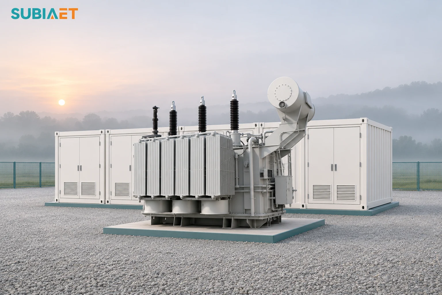
A grid-connected battery energy storage system (BESS) can import active power to charge and export it when discharging, within its approved limits. It may also be required to provide reactive power. A transformer serving such a block must carry the RMS current associated with each coincident operating point at its terminals. Battery energy capacity helps define duration. The rating decision requires translating each dispatch case into a coincident P and Q pair, checking the power conversion system (PCS) capability envelope, and confirming that the cyclic thermal duty remains within the transformer’s permissible loading.
This article walks through the boundary-specific data required to compare candidate MVA values, explains why battery MWh and transformer capacity are fundamentally different quantities, and demonstrates a worked example with three signed operating points that produce conditional shortlist results.
Active power measures the rate of real energy transfer over the stated operating interval, in megawatts (MW). Energy capacity, in megawatt-hours (MWh), may describe nominal battery energy or usable energy on a declared DC or AC basis. A transformer’s apparent-power rating, in megavolt-amperes (MVA), relates to its rated RMS winding current at rated voltage.
The usable energy divided by a comparable constant power level estimates how long the battery can sustain that power level at the same electrical boundary, assuming the permitted state-of-charge window, ambient temperature, and operating constraints remain stable throughout the period. The NREL Storage Futures Study distinguishes power capacity, energy capacity and duration. Determine winding current from the coincident electrical loading at each operating point. The sequence of those currents matters for thermal duty, and voltage regulation depends on P, Q, voltage, impedance and tap position.
Usable energy is the portion of the nominal battery capacity available under actual operating limits. State-of-charge boundaries, temperature and DC voltage limits can reduce the usable energy available relative to nominal battery energy. When calculating a duration estimate, both the energy figure and the power figure must refer to the same electrical boundary and direction, with consistent treatment of losses and auxiliaries. The round-trip energy efficiency of the BESS does not give either direction’s instantaneous loss or apparent power.
A battery storage block typically comprises the battery itself (operating at DC), a power conversion system that inverts or rectifies between DC and AC, a step-up transformer, collector cables, and a grid point of connection. Identify which equipment converts power, changes voltage, consumes station power or exchanges reactive power. The NERC BESS modeling guideline illustrates separate inverter, collector and substation-transformer boundaries before the point of interconnection (POI).
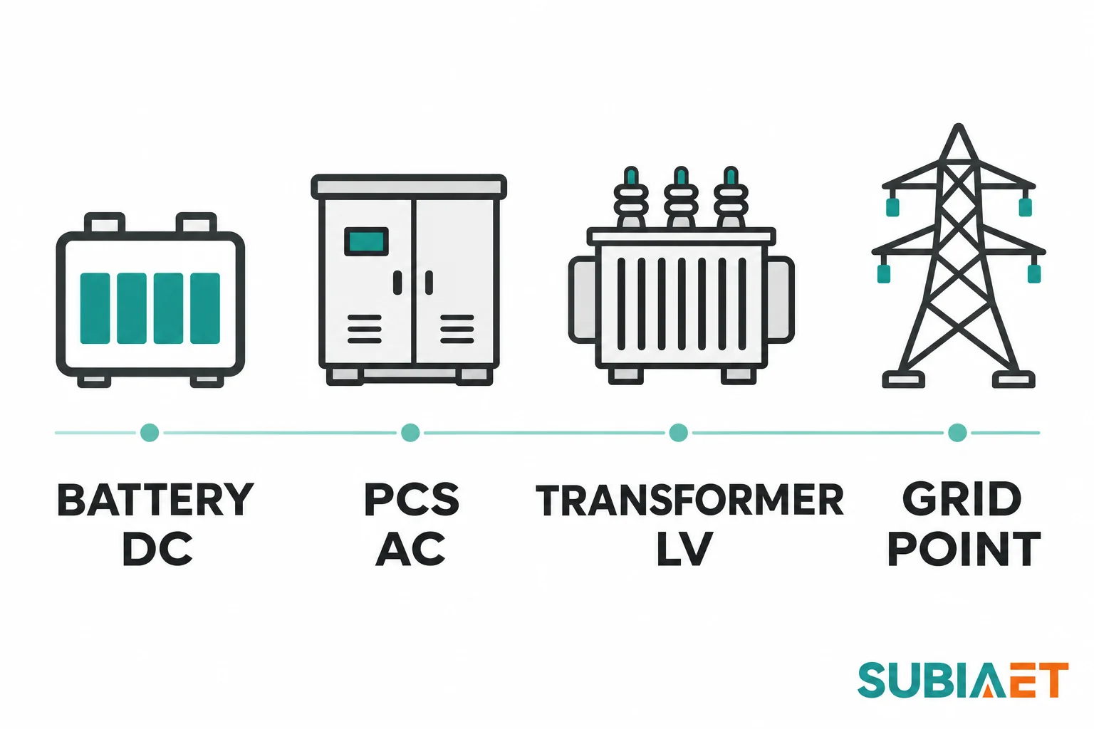
The battery terminals operate at DC voltage and exchange DC power. The PCS converts that DC power to or from three-phase AC at its AC terminals, introducing conversion losses that depend on loading, AC voltage, DC voltage, ambient temperature, and operating mode. Station service loads—such as cooling, control, and communication equipment—may draw power from the battery, from a bus on the AC side of the PCS, or from an independent supply. The location of this auxiliary load determines which boundary accounts for it.
The transformer’s low-voltage winding connects to the PCS AC terminals. Its high-voltage winding connects to the collector or substation bus. Transformer losses occur in the windings and core. Their contribution to the difference between LV-terminal and grid-point power depends on direction and on which equipment lies between those points. Collector cables and any shunt reactive compensation devices further alter the relationship between the transformer’s duty and the grid-point obligation.
Sign convention must be declared consistently. In the worked example below, P is positive for real power flowing from the BESS toward the grid (discharging), and Q is positive for reactive power supplied toward the grid. Charging corresponds to negative P. All simultaneous P and Q pairs are understood to be at the same transformer LV terminal basis, balanced, and approximately sinusoidal for the purpose of comparing candidate transformer ratings.
Define each dispatch case with a coincident pair of signed active power P and reactive power Q at the chosen reference boundary. For a balanced, approximately sinusoidal operating point, the apparent-power screen is
S = √(P² + Q²).
For a balanced three-phase case, the corresponding line current is I = S ÷ (√3 × VLL) with consistent units and the actual terminal line-to-line RMS voltage. Check it against the candidate’s rated terminal current and voltage. Check individual winding duty using the actual connection and winding ratings. Evaluate voltage regulation from the direction and combination of P and Q, impedance and taps. If distortion or unbalance is material, obtain the winding RMS currents and applicable load data directly rather than relying on this screen.
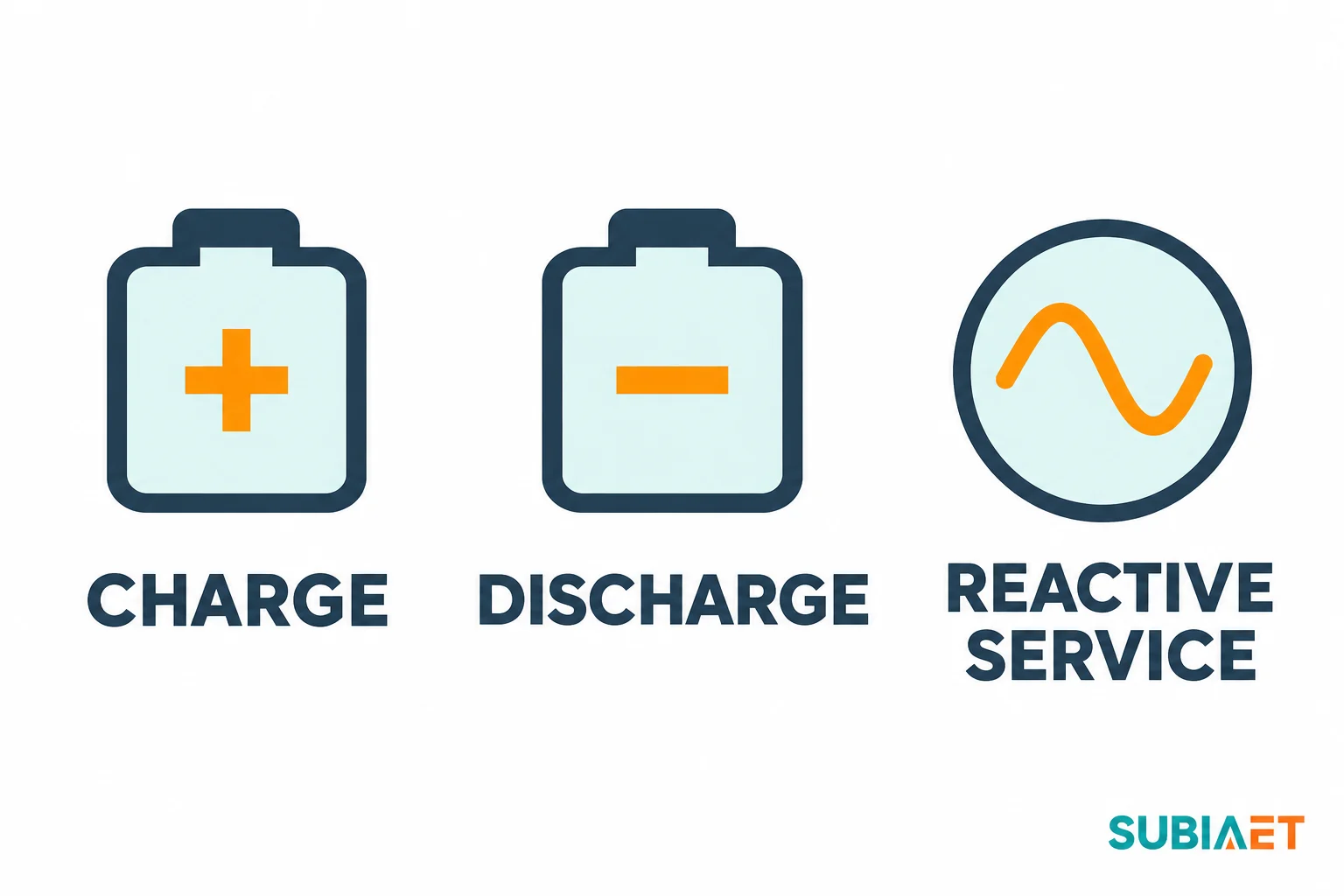
Charging and discharging are separate modes with potentially different PCS capability limits. The SMA Sunny Central Storage UP-XT data sheet illustrates this by listing separate charging and grid-feed apparent power for the named variants at specified DC voltage and temperature. Use the applicable AC voltage and current limits and the manufacturer’s reactive derating information for the offered PCS. Reactive power capability may also differ between the two modes, and some systems can provide reactive support only when active power is present. The ability to supply reactive power at zero net active power—a reactive-only or idle operating mode—must be verified from the actual PCS data and control configuration rather than assumed.
Comparing candidate transformer ratings requires collecting the largest simultaneous apparent-power magnitudes from all specified operating cases. Each case is independent; the transformer does not see an average or a sum of magnitudes but rather experiences the RMS current corresponding to each case when it occurs. Rated current and voltage determine whether a candidate rating arithmetically clears each operating point at nameplate conditions. Harmonics, duty cycle, and thermal loading are checked separately.
The power conversion system has a joint P-Q capability envelope that depends on DC voltage, AC voltage, state of charge (when state of charge constrains active power at a given instant), ambient temperature and control mode. This envelope is not universally square, nor is it always a perfect circle. Some inverters can achieve rated active power and rated reactive power simultaneously under certain conditions; others cannot. Obtain the capability for the specific PCS model, configuration and operating conditions. Ask for transient current and ride-through evidence separately where required.
Use the reactive-power requirement at the measurement point defined in the applicable connection agreement. That point may differ from the transformer LV terminals. Magnetizing current and transformer leakage reactance generally absorb reactive power. Collector cable capacitance, reactors and compensation equipment can change the net reactive exchange between the transformer and the defined point.
Translate the grid-point requirement to the PCS and transformer terminals. Use a documented boundary estimate for early screening and the applicable project load flow for verification, including intermediate sources and sinks of reactive power. A named grid code applies only within its own jurisdiction. For example, EirGrid’s Grid Code Version 18 specifies a particular P-Q capability shape at the Connection Point for its in-scope controllable power park modules consisting of energy storage power stations, and requires those facilities to maintain effective reactive power as import or export changes, including through zero active power. That requirement is scoped to the Irish transmission system and the facility classes defined in the code. It cannot be transplanted to a distribution-connected site in another country or assumed to define the internal transformer duty without mapping the collector network.
When checking a candidate PCS against a grid requirement, verify the PCS capability in both charging and discharging directions, at the expected range of AC and DC voltages, across the ambient temperature range, and for the specified steady-state control modes. Verify required ride-through separately. Confirm that the transformer, cables, and any compensation devices can deliver the grid-point requirement when the PCS operates within its documented envelope.
For an AC-coupled hybrid, check the separate branch transformers. Net flow at a common POI can hide the duty on an individual storage or generation branch. If battery and PV share a PCS on the DC side, check their simultaneous cases against the shared PCS’s joint AC capability and the associated transformer duty.
A transformer’s thermal behavior depends on the sequence, magnitude, and duration of the currents it carries, as well as the ambient conditions, initial winding temperature, cooling mode availability, and any energized standby or reactive-only periods between active-power cycles. Alternating the sign of active power—charging followed by discharging—does not cancel the heating effect. Each direction produces losses, and the cumulative temperature rise depends on the loading profile and the time available for cooling.
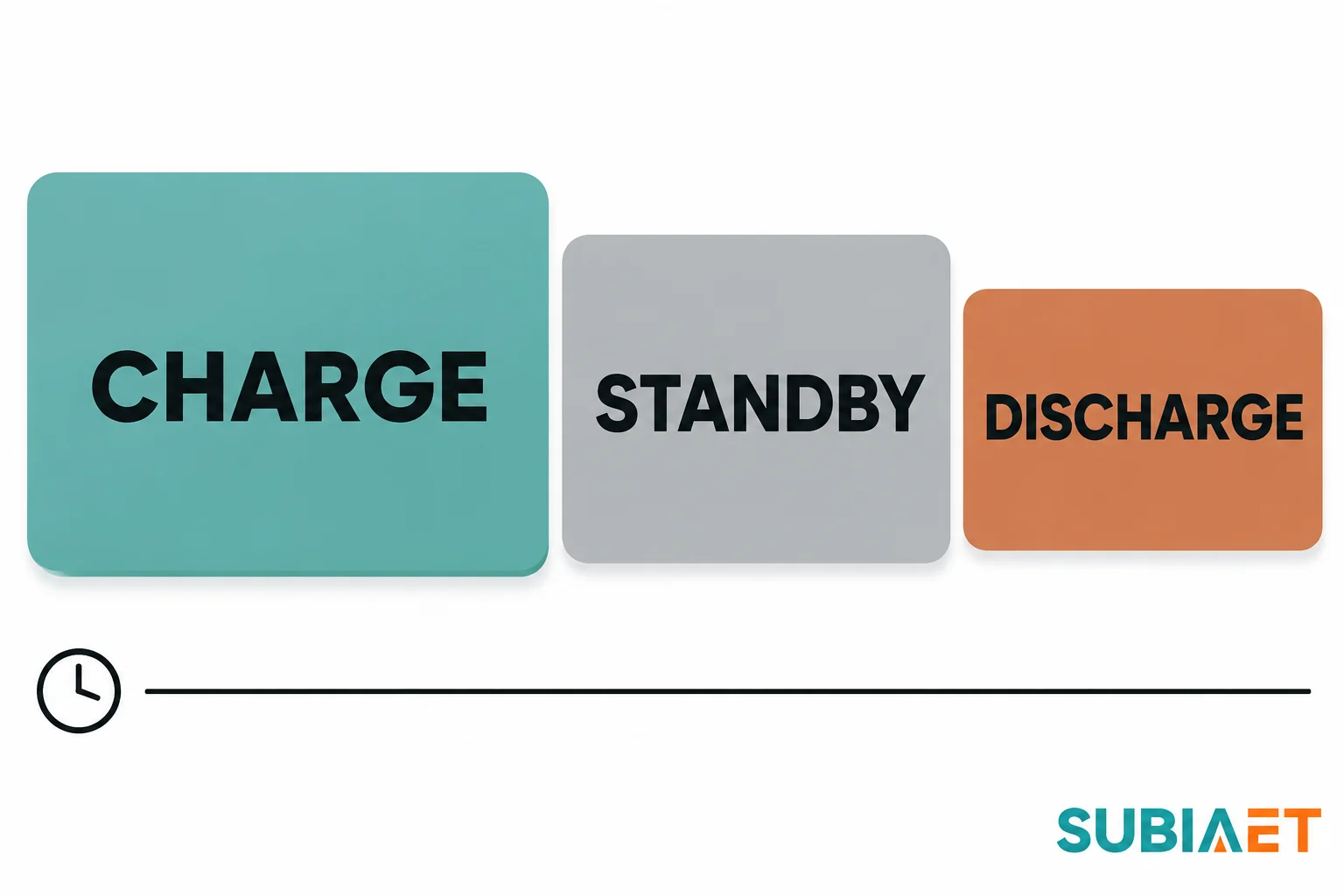
Recording the dispatch schedule means capturing the chronological order of operating points: their kVA or current magnitude, duration, repetition pattern, rest intervals, and any changes in cooling mode or ambient temperature. For example, assess charging, energized standby, discharging and any overnight reactive service in the order they occur. Core losses remain when the transformer is energized, including periods of little or no active transfer. Reactive duty can still drive winding current. Each segment contributes to the winding hot-spot temperature, and the transformer needs to meet the applicable temperature and ageing criteria for the complete cycle.
The public scope of IEC 60076-7:2018 describes loading guidance for mineral-oil-immersed power transformers, relating load and ambient conditions to operating temperature and thermal ageing. It addresses loading above nameplate rating as a subject that requires actual technical assessment of the specific transformer design, cooling configuration, and operating environment. IEC 60076-12:2008 describes a separate loading guide for dry-type transformers within the scope of IEC 60076-11, addressing insulation aging and life consumption as a function of temperature and loading for that construction type. Neither standard provides a universal overload permission or a single thermal capacity factor that applies to all units.
Harmonic currents are considered separately from the fundamental-frequency loading, because harmonics can add winding eddy losses and affect hot-spot temperature. The current spectrum must be provided to the transformer supplier, who can model the additional losses and evaluate the proposed duty against the agreed thermal limits. The presence of harmonics may require derating the transformer’s permissible fundamental load, and that derating is design-specific.
Once the operating points are defined and the dispatch sequence is understood, candidate transformer ratings can be compared at the actual system voltage. Compare the largest simultaneous apparent-power magnitudes with nameplate values and check winding current at actual voltage. If a case exceeds nameplate, require separate documented permissible duty at that current and duration. Check the site-specific thermal rating under actual cooling, ambient conditions and cyclic duty. The transformer’s impedance, winding configuration, insulation system, and cooling method all influence voltage regulation, short-circuit withstand, harmonic tolerance, and protection coordination.
Transformer impedance affects voltage drop under load and fault-current distribution. For otherwise comparable source conditions, lower transformer impedance can raise prospective through-fault current. Evaluate terminal voltage in both power directions and for both signs of reactive power where applicable. Do not infer tap range or voltage rise/drop from impedance alone. The actual impedance value, together with the tap changer type and range (if fitted), must be coordinated with the utility’s voltage regulation scheme and the PCS voltage operating window.
Short-circuit withstand capability must be verified against the applicable external through-fault cases, considering the sources on either side, current and clearing duration. Transformer inrush current affects upstream protection settings and may require coordination with reclosing schemes or capacitor-switching transients. The MVA rating alone does not establish fault withstand or protection coordination.
The SMA transformer-interface note illustrates PCS-specific constraints on the transformer, including AC voltage range, winding connection and vector group, insulation coordination for steep-fronted voltage pulses (dV/dt), and possible continued energization during overnight or off-duty periods. Some PCS configurations require a specific winding grouping or shielding arrangement to limit common-mode currents or meet electromagnetic compatibility requirements. Obtain the interface details from the current specification for the exact PCS and transformer combination.
Station service supply may be derived from the transformer’s low-voltage winding, from a separate winding, or from an independent source. If the declared terminal P and Q figures already include the station service, count it once. Verify the connection point and whether the modeled data are net or gross. If it is supplied separately, the transformer may see additional load or no auxiliary load at all, depending on the connection arrangement.
Base the thermal calculation, harmonic assessment, voltage and impedance study, and short-circuit verification on the offered design and the complete operating duty.
Fictional sizing screen only. The signed setpoints, usable energy and candidate nameplates are assumed for this example.
One transformer serves a battery storage block. At its LV terminals, P is positive for real power flowing from the BESS toward the grid, and Q is positive for reactive power supplied toward the grid. Use the stipulated net LV terminal quantities, including the assumed same-boundary station-service effects. These simultaneous P/Q pairs are separate cases at balanced, approximately sinusoidal conditions. They are not PCS nameplate maxima or grid-point values.
| Case | Signed P or energy | Signed Q or basis | Screen | Decision |
|---|---|---|---|---|
| Charging with reactive service | −2.40 MW | +0.80 Mvar | 2.53 MVA | Verify that the accepted charging and reactive capability supports this paired point. |
| Discharge with reactive service | +3.20 MW | +1.20 Mvar | 3.42 MVA | Largest of the three illustrated terminal apparent-power magnitudes. |
| Reactive-only terminal case | 0.00 MW | +1.80 Mvar | 1.80 MVA | Verify whether zero net terminal MW with this reactive output is achievable, including actual losses and auxiliary supply. |
| Comparable energy window | 8.00 MWh usable AC energy at the same LV boundary | 3.20 MW assumed constant discharge | 2.50 h arithmetic | The duration screen does not set transformer MVA or prove a dispatch schedule. |
| 3.15 MVA candidate | Compare only to the three apparent-power magnitudes | Same LV basis | Below 3.42 MVA | Does not clear the illustrated discharge case at nameplate without an independently justified permissible duty. |
| 4.00 MVA candidate | Compare only to the three apparent-power magnitudes | Same LV basis | Above 3.42 MVA | Clears arithmetic only. Confirm PCS capability, grid-point obligations, voltage/current, harmonics and cyclic thermal duty before approval. |
For the discharge case, S = √(3.20² + 1.20²) = √(10.24 + 1.44) = √11.68 ≈ 3.42 MVA. For the charging case, the magnitude of P is 2.40 MW, so S = √(2.40² + 0.80²) = √(5.76 + 0.64) = √6.40 ≈ 2.53 MVA. The reactive-only case has S = 1.80 MVA.
Comparable energy window: Assume the battery has 8.00 MWh of usable AC energy at the same LV boundary. If discharged at a constant 3.20 MW, the arithmetic estimate is 8.00 ÷ 3.20 = 2.50 h. This duration screen does not set transformer MVA, does not prove that a 2.5-hour dispatch profile is feasible under all SOC and temperature constraints, and does not account for time-varying power or reactive duty during the actual schedule.
The 3.15 MVA candidate is arithmetically smaller than the 3.42 MVA discharge case. Any exception requires independently justified permissible current and duration for the actual dispatch, ambient and cooling, as well as acceptable voltage, protection and other equipment limits. Use the supplier’s thermal model and the project studies. Keep this candidate conditional until that evidence is accepted.
The 4.00 MVA candidate clears all three illustrated apparent-power magnitudes. However, arithmetic clearance is only one check. The selection must also confirm:
The worked example shows that the transformer’s rating cannot be derived from battery MWh alone. The signed P/Q pairs at the transformer terminals govern the comparison, and additional engineering evidence closes the gap between an arithmetic shortlist and an approved specification.
A complete transformer specification for a BESS application requires coordinated input from multiple parties. The operator or project developer provides the dispatch schedule, including all operating modes, durations, and expected frequency of each cycle, as well as measured ambient temperature data for the site. The PCS vendor supplies the joint P-Q capability envelopes in both charging and discharging directions, current and voltage ranges, harmonic spectra at representative operating points, control modes, and any special requirements for transformer winding connection, shielding, or dV/dt withstand.
The grid connection engineer or utility provides the point-of-interconnection model, including the collector network impedance, any static or dynamic reactive compensation, and the grid code requirements that apply to the specific facility class and connection voltage. This information allows the project team to translate the grid-point obligation back to the transformer terminals and confirm that the selected PCS and transformer can jointly satisfy the connection agreement.
The transformer supplier uses the terminal P and Q cases, harmonic data, and dispatch sequence to perform a thermal calculation based on the offered transformer design, cooling configuration, and site ambient conditions. The supplier confirms the nameplate rating, impedance, tap range, winding connection, insulation class, cooling modes, and any design features required to meet the interface and duty requirements. The supplier also provides short-circuit withstand ratings, inrush characteristics, no-load and load losses on the agreed test basis, and design verification test results or calculations as required by the project specification and applicable standards.
Before requesting quotations, have the owner and design team agree the terminal duty, system boundaries and evidence suppliers must return. Before accepting an offer, verify that the selected equipment and controls satisfy the transformer, PCS, collector and connection-point duties.
Related resources: SUBIA’s renewable and distributed energy application overview provides context for storage integration. For foundational concepts, see why transformers are rated in kVA. Evaluating quotations should include transformer losses and total cost of ownership. Harmonic duty is covered in when to review derating or a special design. Inverter-transformer interface considerations appear in solar inverter transformer selection: voltage, vector group, and impedance. For withstand verification, see transformer short-circuit withstand: what evidence should buyers request.
No. That calculation estimates a power level at a stated boundary, but it does not directly set transformer MVA. The transformer must handle the apparent loading at each defined operating point, including simultaneous active and reactive components. A battery’s energy capacity and a transformer’s apparent-power rating are fundamentally different quantities. Use the simultaneous signed P and Q pairs at the transformer terminals to calculate the apparent power magnitude for each operating case, then compare candidate MVA ratings against those magnitudes while verifying the cyclic thermal duty separately.
The transformer’s permissible loading depends on the actual sequence, magnitude, duration, ambient conditions, and cooling mode of the cyclic duty, not merely the fact that the load alternates direction. Charging and discharging both produce losses that heat the windings. Whether a given duty cycle requires derating or permits operation above nameplate depends on the specific transformer design, the thermal time constants, the rest periods between cycles, and the ambient temperature. The transformer supplier must perform a thermal calculation using the actual dispatch schedule and the offered unit’s thermal model. There is no universal rule that daily cycling always requires derating or always permits continuous nameplate operation.
Not necessarily. Some power conversion systems can deliver rated reactive support with zero net active power at the terminals, while others cannot. The capability depends on the PCS design, control strategy, DC voltage, and AC voltage conditions. If reactive-only or idle operation is a specified mode, request the PCS vendor’s documented capability for that mode, including its reactive limit, duration and operating conditions. At zero net MW at the declared terminal, verify how losses and auxiliary loads are supplied and measured. Do not assume that the ability to provide reactive power during discharge or charge automatically extends to zero active power.
