Request a Quote
Share the equipment and project requirements. If you need help selecting a model, describe the application.
Have drawings or specifications? Email [email protected] with your project reference.

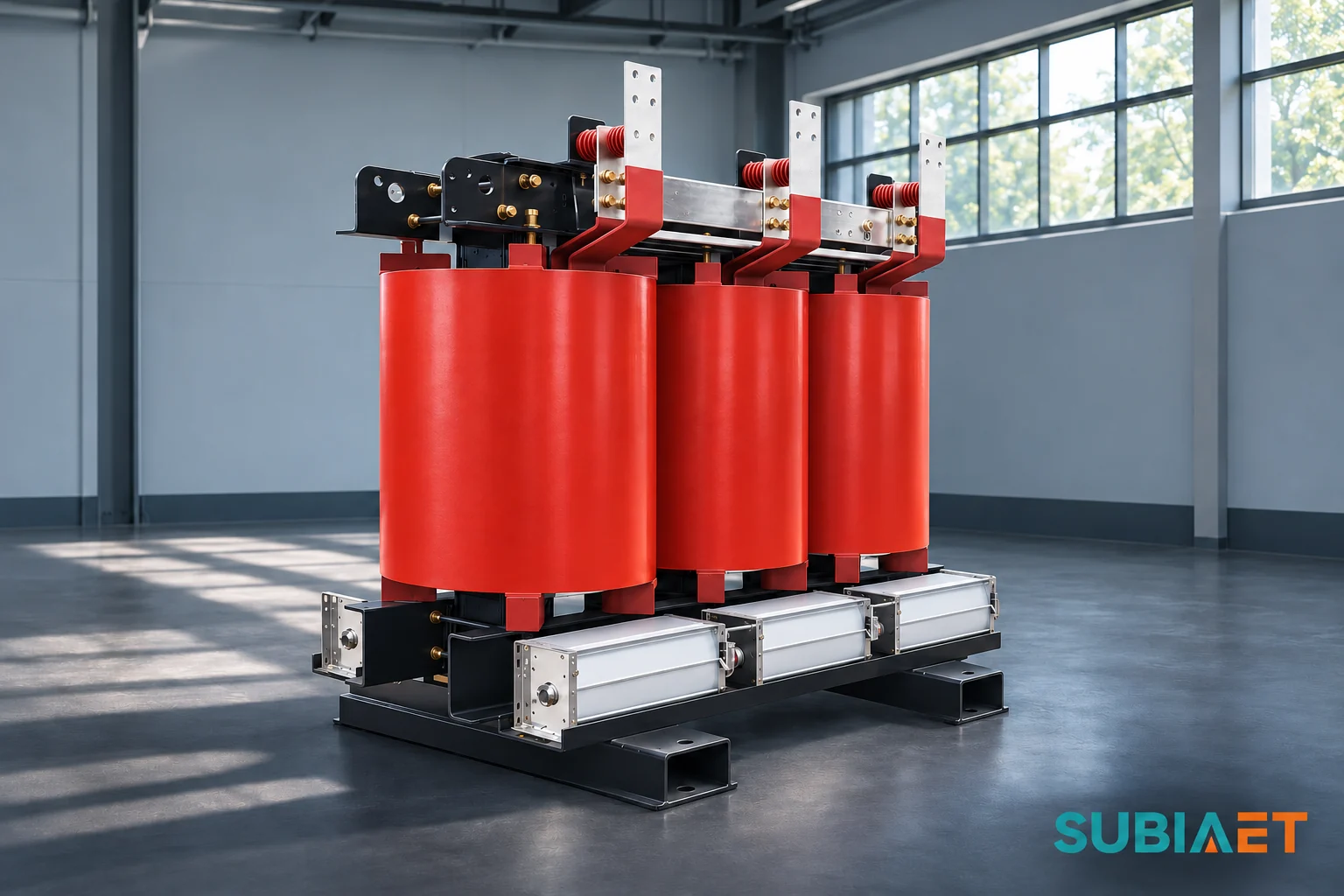
Protection coordination needs a set of configuration-specific energization cases expressed on the measurement basis the fuse, breaker, CT and relay actually use. It also needs an independent demonstration that the proposed scheme detects and clears the required faults in time, including the smallest fault it must detect. Those are two separate evidence streams, and passing one says nothing about the other. This article works through what inrush current physically is, which energization cases a network can generate, what to demand from the transformer supplier, how to put the data on the protection device’s own basis, what each protective function must be checked for separately, and how to hold an approval open when the data is not yet there.
The change in core flux follows the volt-seconds across the winding that excite the core. After de-energization, the core can retain remanent flux. Its magnitude and direction depend on the magnetic and switching history. The flux on re-energization starts from that retained value. At an unfavourable closing point, the applied voltage can drive the flux further in the same direction, taking the core into saturation and sharply reducing its effective magnetizing inductance. The CIGRE UK transformer energisation insight illustrates how the retained flux and breaker pole closing instants can affect that excursion.
The result is a large, asymmetric, decaying current drawn from the supply into the energized winding. The source impedance behind the breaker and the saturated winding impedance influence its magnitude. The waveform can start with a large unidirectional component and gradually settle toward the steady excitation current. Its decay depends on circuit losses and the transformer’s magnetic behaviour. Inrush can be offset and non-sinusoidal, and its harmonic content can change cycle by cycle.
A transformer can draw this transient with its secondary open. The magnetizing current supplies the core even at no load. With load connected, the feeder can also carry load pickup during the same event. Distinguish these currents in the coordination review:
Only the first of these is close to inrush in character, and only in the sense that both are magnetizing-branch phenomena. Inrush is a saturation transient; steady excitation is the settled state of the same branch.
Residual flux and the closing instant together decide how deep the excursion goes. Neither is predictable with certainty in service. Remanence depends on the flux at the previous interruption, which depends on the previous switching event; the closing point depends on breaker pole mechanics and control. That is why there is no universal worst closing angle to design around in the abstract — the worst combination is a property of a specific transformer, a specific residual-flux history and a specific switching device. It also means that a harmonic ratio cannot settle the question of what happened. The SEL field-case study on low second-harmonic content shows healthy magnetizing inrush with low second-harmonic content under deep saturation, and CT behaviour plus waveform processing can further change the observed quantity. Use the harmonic content alongside the event record, CT behaviour and system state.
One more distinction matters before any coordination decision: the current transient, the network RMS voltage drop it produces, and any temporary overvoltage are three different quantities with three different assessment methods. A study optimised to bound a voltage dip is not automatically bounding the current a fuse or relay sees.
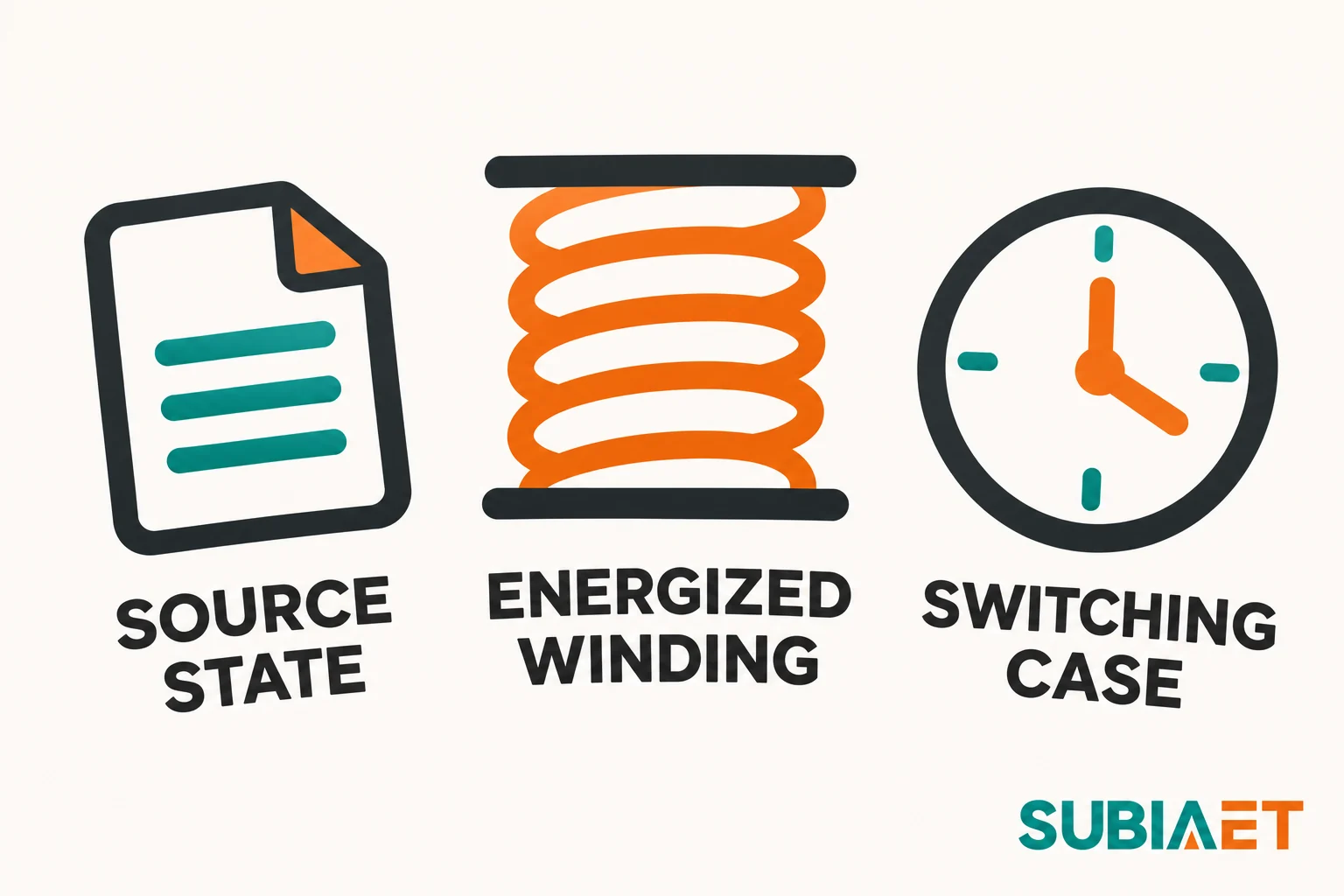
Protection coordination is approved against a set of cases, not against a transformer. The same unit can produce very different energization currents depending on how and where it is switched, and the study is only as good as the case list behind it. The inputs that define a case fall into three groups.
Source state. Which upstream source is feeding the transformer, what its impedance and topology are at the moment of switching, and what the voltage and frequency are at the terminals. Higher source impedance can limit current and increase terminal voltage depression. Current magnitude, shape and decay also depend on the transformer and switching conditions. Neither direction is automatically the worst case for every protective function — the case that produces the largest initial current may differ from the deepest dip or longest response. Include the normal and alternate source conditions that can occur.
Energized winding. Which winding is switched, at which tap, and with what connection arrangement. Energizing from the HV winding with the LV open is a different case from backfeed from the LV side, and the tap in service changes the volts-per-turn and therefore the saturation margin. Winding geometry and connection affect how the transient distributes between phases and how it appears to a CT on a given side. It is not safe to assume one winding always produces the larger inrush; that is a per-configuration result.
Switching case. Whether the poles close together or staggered, what point-on-wave each pole sees, what residual flux is assumed, whether this is a first energization or a reclose after a trip, and whether other transformers are already energized on the same bus. Reclose is a distinct case because the core state and connected load after a trip can differ from a planned de-energization. Backfeed through a downstream source is a distinct case because the energized winding, source impedance and measuring location can differ. An adjacent transformer operating in parallel is a distinct case because of sympathetic inrush: switching one unit can drive a transient magnetizing current in a neighbour already in service. It can develop differently from the initial current and affect protection at the measuring locations.
Sympathetic inrush and the voltage dip at the point of common coupling are both case-specific outcomes, not properties of the transformer alone. The UK ENA Engineering Recommendation P28 for rapid voltage change assessment does consider upstream source conditions, initial voltage, remanence, closing point and sympathetic inrush where relevant, and it treats current asymmetry and the fundamental and DC components as separate quantities with transformer-specific damping and decay assumptions. That is a power-quality framework with its own assessment windows and limits, not a current-processing definition — a conservative voltage-dip case is not automatically the maximum current a fuse or relay sees.
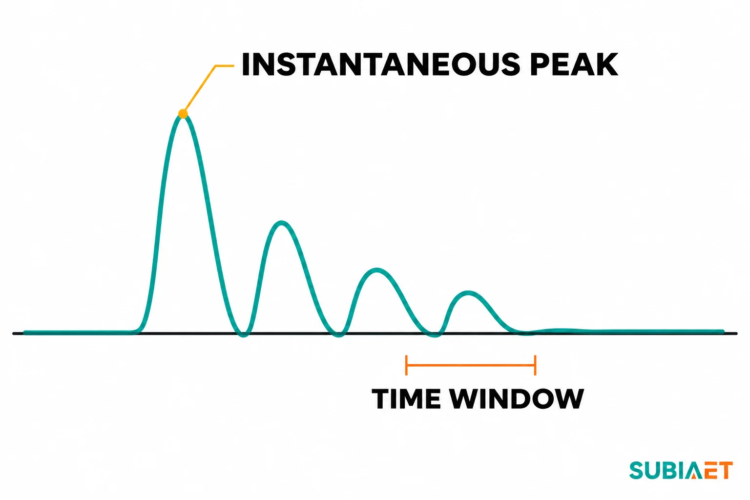
A single peak current value is one part of the supplier’s submission. The protection study needs an envelope covering the declared energization conditions for the offered configuration, with the conditions for each case and the basis for the bounds stated.
Ask for these items explicitly, in writing, as a submission rather than as an email sentence:
Push back on a submission that quotes a multiple of rated current without a trace. Multiples invite exactly the error this article is trying to prevent: comparing a peak to a curve that was never plotted in peak terms. The envelope should let the protection engineer build the case list from the supplier’s own conditions rather than guessing at them.
This is the step where most coordination reviews quietly fail. An inrush trace and a protection characteristic are both “current versus time,” but they are not automatically in the same units, on the same window, or referred to the same winding.
Instantaneous amperes describe current at a point in time. For a reported peak, record the phase, polarity or absolute-peak convention, measuring side, sample resolution and time reference. The instantaneous peak of an asymmetric event may include the offset.
RMS is defined over an interval. A full-cycle RMS is the root-mean-square of the samples across one complete power cycle; a half-cycle RMS uses a shorter window and can give a higher or lower value on a decaying offset waveform, depending on where that window falls. Both are legitimate, and they are different numbers for the same event. Any RMS figure must therefore carry its window definition and processing with it.
Fundamental or filtered estimates depend on the element and its signal processing. An element may compare the filtered fundamental, while another uses an RMS or other defined quantity. A differential relay may also calculate harmonics from its operating quantity. Obtain the definition for the actual element and distinguish a raw waveform from the relay’s filtered event data.
CT ratios and device scaling put the trace and the characteristic on the same current basis. For a conventional CT input specified in secondary amperes, account for the actual ratio once. Verify the scaling for any low-energy or sampled input and the winding used as the reference. Use the CT performance and compensation relevant to the device and scheme when the waveform itself matters.
The sinusoidal peak-to-RMS conversion assumes a pure sine wave. An offset, decaying inrush waveform does not meet that assumption. Compute RMS from the actual samples over the stated window, or use a value supplied on the required basis. For any curve comparison, identify whether it is minimum melting, pre-arcing, total clearing, definite time or inverse time, and apply the supplier’s accepted current convention and method.
The practical resolution is to ask the device manufacturer for the plotting and evaluation method that applies to their product: which current quantity the characteristic is expressed in, over what window, referred to which winding and CT ratio, and with what tolerance. Document the answer alongside the calculation, including the reference winding and the device-specific operating behaviour, so that a later reviewer can reproduce the comparison without re-deriving the conventions.
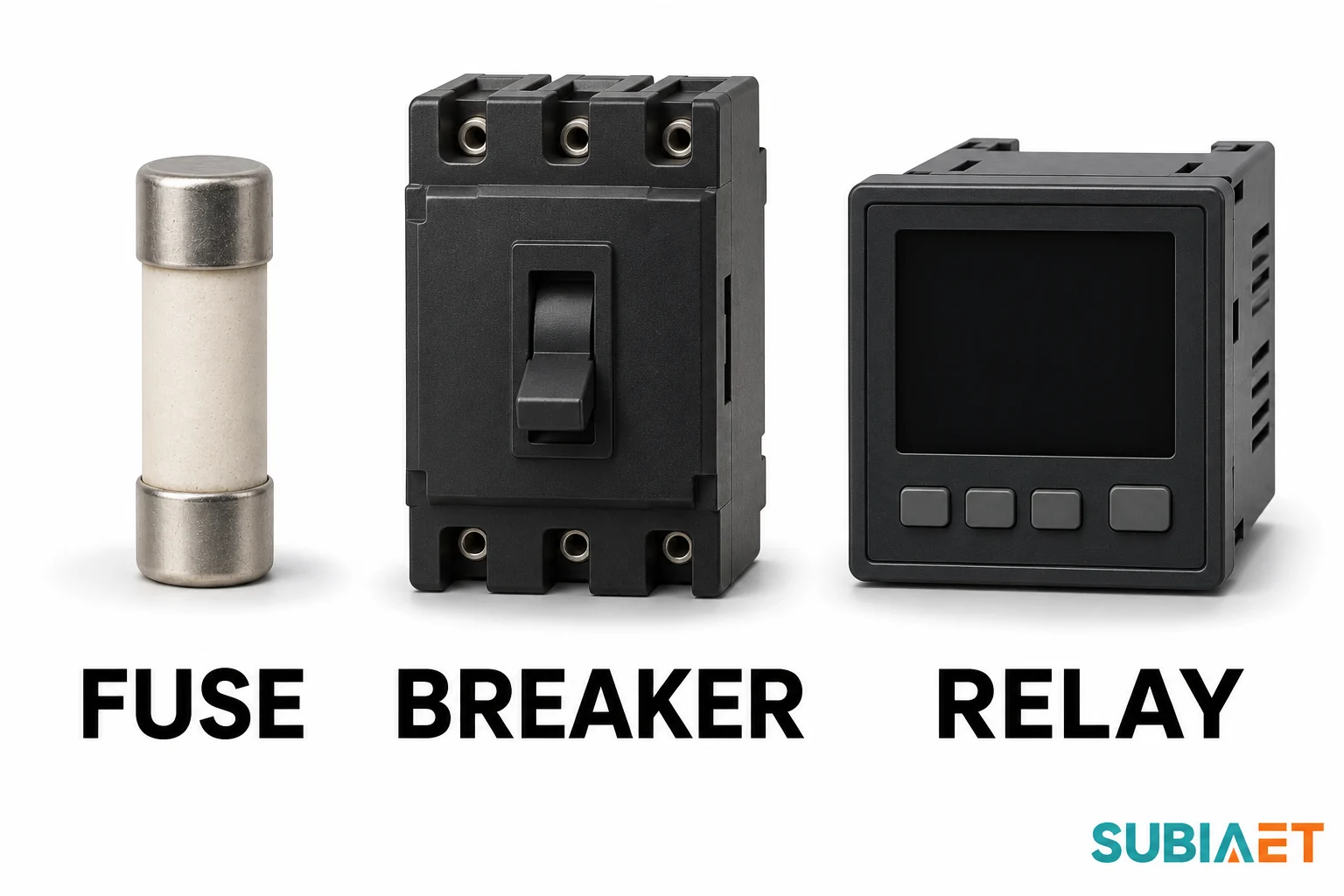
Three device families answer three different questions, and a review that treats them as interchangeable will approve something it has not checked.
Fuses. A fuse has two distinct characteristics that must not be merged. The minimum-melting or pre-arcing characteristic provides the no-melt comparison. The S&C application guide for SMD power fuses compares the inrush and hot-load duty against that minimum-melting characteristic, with preload and ambient treatment applied where the family requires it. That comparison answers ride-through: does the fuse survive the energization without melting? Use the actual fuse supplier’s method and curve revision. The maximum or published total-clearing characteristic is a separate curve with a separate purpose — fault protection and selectivity — and it answers when the circuit is actually interrupted. A minimum-melt ride-through check cannot establish total fault clearing, and any comparison of currents must be referred to a common voltage with the applicable fault treatment applied, because transformation of fault current depends on connection and fault type.
Breakers. The Schneider ComPacT NSX guide shows that the named low-voltage trip units may offer short-time pickup, short-time delay and an instantaneous element, and the availability and adjustability of each varies by trip-unit variant. Thermal memory is documented as a function separate from the instantaneous element. Check the actual integral trip unit or external relay used in the project. Also worth stating plainly: an instantaneous element has no intentional delay in its instantaneous mode. Physical interruption still takes time. Relay or trip-unit operate time is not the same as end-to-end circuit interruption, which includes the breaker’s own mechanical and arc-quenching time.
Feeder relays. The SEL-751 data sheet documents instantaneous or definite-time elements alongside inverse-time elements, selectable reset behaviour, and separate transient and steady-state pickup tolerances. Its conventional input specifications refer current to CT secondary amperes. It provides oscillographic records with raw or filtered analog data and records of element state changes. Identify which element and data format were used for the replay.
Differential functions. Percentage differential bias uses restraint derived from measured currents. An inrush function can add harmonic restraint or block operation of a specified differential element. The GE Vernova MiCOM P34x manual documents one family’s second-harmonic blocking based on the filtered differential current, with phase-specific or cross-blocking options and distinct high-set paths. The second-harmonic content of a real inrush event is model- and event-dependent. Recorded and modelled cases include healthy magnetizing events with low second-harmonic content under deep saturation, and CT behaviour plus waveform processing can shift the measured ratio further. Consequently, check the device’s actual logic and validate it for both inrush and real faults, including an internal fault during energization where the study calls for it. A broad change to harmonic blocking or restraint can affect dependability for a real fault.
Inrush ride-through and fault clearing are independent requirements. Verify that the relevant protective functions tolerate the validated energization cases and operate as required for the faults assigned to them. Use the complete device chain to establish timely interruption.
Run the required fault cases as a separate exercise with the same proposed devices and the applicable measurement and clearing conventions. Both evidence streams must close before coordination approval.
Use the fault set and operating conditions required by the project study. Maximum external fault tests the through-fault path and must be compared against the transformer’s applicable short-circuit withstand limits as well as against the device’s clearing capability. Minimum external fault cases check whether the assigned protection still operates for the low fault currents it must detect and clear. Internal fault cases check detectability and clearing for the relevant in-zone locations and source conditions, including high fault duty and minimum sensitivity where applicable. Review the differential or other elements assigned to each case, including a high-set path only where the scheme uses it. Verify internal fault during energization where the governing study requires it.
Each case must be evaluated with the CT performance that actually applies. A CT carrying a fully offset asymmetric current can saturate on the offset, and its remanence from a previous event changes what it delivers next time. Ratio alone is not enough; the class, the burden and the offset behaviour all enter. Where a CT saturates, the relay sees a distorted, possibly reduced fundamental, even if the primary fault current matches the calculation.
Main and backup clearing should be evaluated as separate scenarios rather than assumed. If the primary device fails to clear, the backup path may see a different current, at a different point in the network or after a different delay. Record the interruption time on the approved basis for each required path.
Where the utility imposes voltage-change or rapid-voltage-change criteria, those run alongside the current checks with their own assessment basis and limits. They are not a substitute for the current evaluation, and a case chosen to bound a voltage dip should not be reused as the maximum-current case.
Finally, resist the blanket trade. An inrush correction can change fault sensitivity or clearing. Re-evaluate the required fault cases against any proposed change. The correct handling is to keep both requirements visible, satisfy each on its own evidence, and record explicitly which cases are closed and which are open.
Fictional engineering review only. The case is not a setting, a product guarantee or a typical inrush multiple.
Project case. One 50 Hz three-phase transformer is energized from its HV winding at the principal tap with the LV open in the documented normal source configuration. The supplier reports one simulated scenario, with the stated residual-flux and closing assumptions. All sample amperes are primary amperes of that same HV winding and reported phase. A cycle is 20 ms at 50 Hz.
| Item | Basis | Supplied result | What it establishes |
|---|---|---|---|
| Initial peak | One simulated phase trace | 430 A instantaneous peak | Record this as a peak field only. It does not populate an RMS curve. |
| RMS history | First and fifth complete cycles, same reported phase and reference winding | 185 A RMS and 96 A RMS respectively, supplied as separate trace measurements from the simulated waveform | Two defined time windows from the single scenario. No peak-to-RMS conversion. |
| Exact feeder device replay | Evaluated by the protection engineer with the proposed CT and relay model and approved current/measurement convention | Model gives no trip for that one simulated energization trace | One scenario checks out under stated assumptions. Retain input and logic revision. |
| Other energization cases | Alternate source topology, re-energization and adjacent energized transformer | No matched waveforms or envelope supplied | Energization review remains open. Request applicable cases, including any sympathetic response. |
| Fault clearing | Minimum required fault case under the project study and its specified clearing basis | No validated response for the proposed device yet | Fault protection remains open separately. Do not infer it from the no-trip replay. |
| Release decision | Protection engineer and system owner must close the required study cases | Supplier and system engineer own missing data. Protection engineer owns verification. | Hold the coordination approval until required evidence and independent fault check are complete. |
The 430 A is the instantaneous peak from one phase of one simulated trace. The 185 A and 96 A values are RMS results calculated over the first and fifth complete cycles, respectively, using the same phase and HV winding reference. Each full cycle lasts 20 ms at the stated frequency. These are separately supplied results from the same waveform. A sinusoidal peak-to-RMS conversion cannot recover either reported window.
The replay result is genuinely useful, but its scope is narrow: under the stated residual flux, closing assumption, source configuration and tap, with that specific CT and relay model and a defined measurement convention, this one simulated trace produces no trip in the proposed replay. Retain the inputs and logic revision, and record the reported phase and other input coverage. It does not establish ride-through on a reclose, because the core state and connected load may differ. It does not establish anything about sympathetic inrush, because no adjacent energized transformer was represented. It does not establish fault clearing, because the minimum required fault response has not been validated. The example does not establish which part of the device logic led to the no-trip outcome. And it says nothing about alternate source topologies, where the source impedance changes both the magnitude and the shape of the transient.
The release decision row is the point of the exercise. Missing energization data belongs to the supplier and the system engineer. Verification against the actual device logic belongs to the protection engineer. Approval belongs to the system owner, and it stays on hold until both evidence streams are complete rather than until the most convenient one is.
The gaps in the worked example are ordinary, and they close the same way in most projects: assign each input an owner, state what the evidence must contain, and set the two points at which it is checked. Nothing in this checklist is a switching instruction; it is a record of what has to exist before coordination is approved.
| Input | Owner | What the evidence must contain | Design freeze | Final as-built |
|---|---|---|---|---|
| Inrush envelope | Transformer supplier | Configuration and revision identifier; energized winding and tap; rated-current reference; per-phase instantaneous peaks; traces with time base; RMS/algorithm window definitions; point-on-wave, residual flux, voltage and source assumptions; tested versus simulated; limiting-case rationale; repeated cases | Required | Re-confirm against as-built tap, connection and revision |
| Energization case list | System or utility engineer | Source topology and impedance per case; voltage and frequency at closing; switching mode including staggered pole closing; reclose and backfeed cases; adjacent energized units and sympathetic inrush relevance | Required | Confirm against final network configuration |
| Voltage-change criteria | System or utility engineer | Applicable assessment basis and limits where the utility requires them, kept distinct from current evaluation | Required where applicable | Confirm applicability unchanged |
| Device characteristics and logic | Switchgear, fuse or relay provider | Exact family and variant; firmware revision; element set and curve basis; instantaneous, definite-time and inverse-time definitions; tolerances; CT ratio and reference winding; harmonic restraint and blocking logic | Required | Confirm firmware and variant match what was studied |
| CT performance | Switchgear provider with protection engineer | Ratio, class, burden, saturation behaviour under offset current, remanence considerations | Required | Confirm installed CTs match |
| Energization verification | Protection engineer | Case-by-case replay against approved device logic and measurement convention; retained inputs and logic revision; open cases listed | Required | Retained with as-built revision |
| Fault clearing verification | Protection engineer | Required external and internal fault cases and relevant low and high fault duties, approved clearing basis, main and backup scenarios and applicable through-fault limits | Required | Reassess if the hardware, configuration or network assumptions change |
| Commissioning and approval record | Commissioning lead, protection engineer and system owner | Installed equipment, settings and study revision checked against the approved design, with applicable verification records. Name the owner of each open case and the condition for release. | Hold if a required study case is open | Record approved closure and verify the as-built scheme before service release |
Compare the as-built condition with the approved design at the second checkpoint. A tap change, a firmware revision, a substituted CT, an added parallel transformer or a different upstream source can affect part of the study. Assess the applicable impact, update the study or approved disposition where required, and keep the installed equipment and settings traceable to the record. Re-confirming at as-built is cheaper than discovering the mismatch after a nuisance trip.
The supplier owns the transformer data and the protection engineer owns the coordination assessment. The commissioning lead confirms the installed equipment, logic and settings match the approved basis and records any deviations for review. Assign an owner and a release condition to every outstanding item.
Related reading:
Inrush is a temporary magnetizing current caused by core saturation after a change in applied voltage, including energization with the secondary open. Fault current flows into a fault path and depends on the actual fault and network. Their waveforms can overlap in magnitude or appearance at a protection element. Check recorded currents, voltages and device behaviour, and verify inrush ride-through and fault clearing as separate study cases.
A fuse curve uses the manufacturer’s defined current and time basis. Obtain the accepted representation of inrush duty for that fuse, along with any relevant preload and ambient treatment. Compare on a common voltage reference. A single asymmetric peak or its sinusoidal peak-to-RMS conversion cannot supply the curve input. Use minimum melting to check inrush ride-through and the appropriate total-clearing characteristic to check fault interruption.
A healthy magnetizing event can show low second-harmonic content, and CT behaviour and relay processing can affect the reported ratio. Review the waveform, relay event record, CT response and switching assumptions together. Use the approved device-specific fault and energization checks to establish how the protection should behave.
The approval record should bring together the validated energization cases and separate evidence for detecting and clearing the required faults. Include the applicable main and backup cases, CT performance, clearing time basis and as-built disposition. A single simulated no-trip replay covers one scenario. List the remaining cases, their owners and the release condition.
