Request a Quote
Share the equipment and project requirements. If you need help selecting a model, describe the application.
Have drawings or specifications? Email [email protected] with your project reference.


When you receive quotations for an indoor low-voltage power switchgear and controlgear assembly, ask two questions. Does the design evidence cover the offered configuration? Does the routine verification record match the unit that will ship? Design verification covers the applicable characteristics of the design. Routine verification covers the manufactured assembly. The two verification roles can belong to the same company or to different companies. Agree on the evidence you need at each buying stage.
Buying an assembly means you need evidence that covers the quoted arrangement and a traceable as-built record for the unit that ships. This guide explains which IEC 61439 parts apply, how to check design coverage against your actual configuration, who owns verification when changes occur, what a routine record should show and where component certificates and factory acceptance tests fit. A worked example with two bids at the same headline ratings shows how the evidence changes the release decision, and the final section provides copy-ready procurement requests for tender, manufacture and shipment milestones.
Design verification addresses a representative design or configuration. It demonstrates that an arrangement of busbars, supports, enclosures, cable entries, protective devices and auxiliaries meets the applicable characteristics when built and loaded in a defined way. The original manufacturer develops the design, performs applicable design verification and supplies selection and assembly instructions. The original manufacturer role attaches to the design itself. One company can be both the original manufacturer of a design family and the assembly manufacturer building a specific order.
Routine verification applies to each manufactured assembly. The assembly manufacturer builds the actual configuration and performs the applicable routine checks during or after manufacture on each assembly or relevant transportable unit. The checks address the as-built unit’s construction and performance against the applicable requirements and design. Request a traceable record for the delivered assembly as part of procurement.
Design verification. The object is a design or configuration, supported by evidence appropriate to each characteristic. The original manufacturer is responsible for its design verification. Ask for the design family, applicable reports, coverage schedule and limitations. At tender or design review, confirm the design coverage available and agree when any outstanding verification must be closed.
Routine verification. The object is the manufactured assembly or the applicable transportable units. The assembly manufacturer is responsible for the applicable checks during or after manufacture. For shipment release, request the assembly or transport-unit identifier, drawing revision, criteria, results, exception closeout and sign-off.
Testing a representative arrangement is one permitted design verification route. The applicable product part, edition and characteristic determine when reference-design comparison or assessment is permitted. The BEAMA verification guide, covering the 2021 UK adoption, notes that verification of a bespoke feature can take place during manufacture, including alongside routine verification. The evidence still addresses the design of that feature. A design test report has a defined coverage scope, and passing routine checks leaves any unsupported variant to be assessed separately.
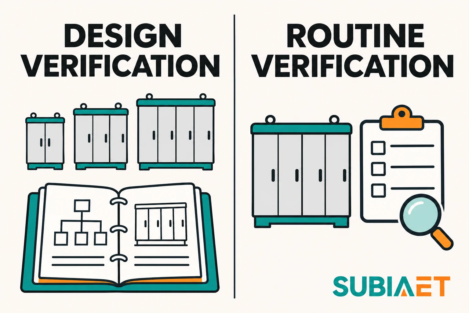
When one company performs both roles, keep the records tied to their respective objects. Ask for the applicable design evidence and an as-built routine record that identifies the shipped assembly.
IEC 61439-1:2020 supplies general definitions, service conditions, construction requirements, technical characteristics and verification requirements. For assembly conformity, use the applicable product part from Part 2 onward together with the cited Part 1 provisions. The IEC public synopsis distinguishes product-standard tests for drives, uninterruptible power supplies and power electronic converters from verification of their incorporation into an assembly. It also identifies group rated current as an edition change relevant to temperature-rise verification. The current publisher copy includes two corrigenda.
IEC 61439-2:2020 is the specific product part for power switchgear and controlgear assemblies within the published scope. Its public synopsis identifies a temperature-rise route combining comparison with a reference design and calculation for certain naturally cooled assemblies. It also describes additions concerning verification and ingress protection for certain actively cooled assemblies. For the method used on the offered design, ask the manufacturer to identify the applicable provision and show that its conditions are met.
IEC TR 61439-0:2022 gives guidance on the system and application information the specifier provides to the assembly manufacturer. The third edition assumes conformity to the applicable product part and supersedes the 2013 second edition. Use it to specify interfaces, service conditions and functional requirements before deciding which design evidence applies.
Verify the edition, national adoption reference and any contract-specific edition in your project documents. Separately, confirm that the assembly scope matches the product part. An LV PSC assembly covered by Part 2 is not the same as a component tested to its own device standard, an empty enclosure without functional units, medium-voltage switchgear or assemblies for other dedicated applications covered by different product parts. Do not assume that all low-voltage panels fall under the same part or that the general IEC 61439 family name is assembly-specific design evidence.
Ask the builder for the offered drawing, ratings and a coverage schedule by design characteristic. The schedule should identify the design family, issue, general arrangement, busbar system and supports, functional units, enclosure and cable-entry arrangements, ratings, loaded arrangement and applicable service assumptions. Match these details to the quoted configuration. If the offered arrangement does not appear in the supplied evidence, the gap must be closed before you proceed.
Different characteristics permit different verification routes. Testing a representative arrangement, comparing with a tested reference design, and assessment each have their own applicability and limits. The BEAMA guide’s Table 1 for the 2021 UK adoption lists assessment for incorporating switching devices and components, testing for power-frequency withstand design verification, and testing, reference-design comparison or assessment for temperature rise, subject to the relevant conditions. For short-circuit withstand, it lists testing or comparison. A calculation under the described short-circuit comparison route still compares with a tested reference and must meet the route’s conditions.
Take temperature rise, short-circuit withstand and enclosure protection as examples of distinct evidence paths. Temperature-rise verification for a loaded arrangement can support a group rated current for a main circuit under stated simultaneous loading and layout conditions in the same section. The Schneider Electric paper on assembly current ratings shows an example where enclosure ingress-protection configuration and circuit position changed the temperature-rise results. Share the actual load profiles and circuit positions with the assembly manufacturer, then check the limits shown in the applicable evidence.
Short-circuit withstand requires assembly evidence for the offered busbar and protective-device arrangement. A component breaking rating describes the device on its stated basis. The 2023 BEAMA guide to the 2021 UK adoption separately addresses thermal substitution and short-circuit coverage. The limited thermal comparison it describes depends on an essentially unchanged physical arrangement and on the substitute’s power loss and terminal temperature rise being no greater on the stated comparison basis. Check fault performance, enclosure protection and any other affected characteristics separately.
Enclosure protection evidence should cover the actual cable-entry arrangement. A revised entry might be a documented option under existing evidence. If its applicability cannot be demonstrated, obtain the relevant verification for the affected characteristic. Apply the appropriate route to the exact edition and configuration.
Seek a coverage matrix that maps each characteristic to the referenced reports and identifies any limitations. Where design documents are proprietary, agree on access to relevant excerpts or summaries that allow you to confirm coverage without requiring full handover of the manufacturer’s design database. Contractual document access and format are procurement choices, not universal IEC mandates.
Changes within an approved verified option remain covered when the conditions of that option are met. Arrangements outside existing coverage require new or extended verification of the affected characteristics. Where the assembly manufacturer develops and introduces its own uncovered design change, it takes the original manufacturer’s verification responsibility for that change. Where another original manufacturer supplies the changed design and its verification, identify that role and link its evidence to the final assembly.
The assembly manufacturer closes verification gaps by showing that the change falls within an existing verified variant, providing the applicable evidence when it is responsible for the changed design, or obtaining it from the original manufacturer of the new arrangement. Document the affected characteristics, applicable verification and allocation of responsibilities.
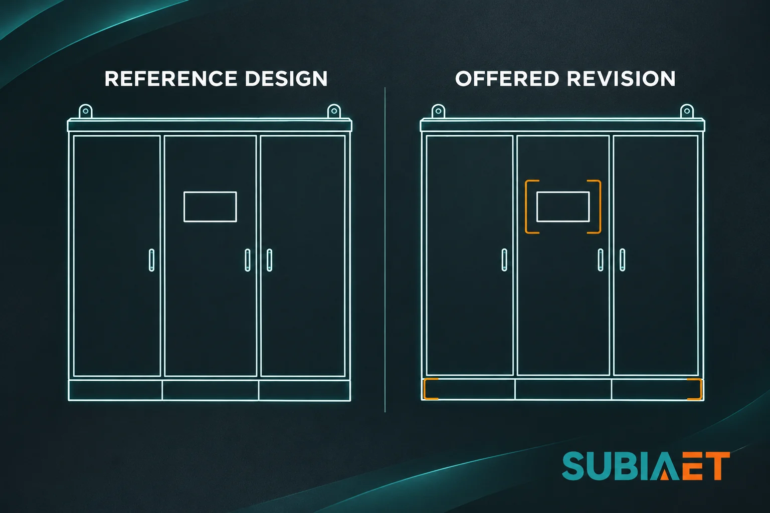
For breaker changes, busbar supports, cable-entry revisions, ventilation modifications and internal partitions, trace the characteristics the change affects. A breaker substitution can affect temperature rise and short-circuit duty. Busbar support changes may affect short-circuit mechanical withstand. Cable-entry revisions may affect ingress protection or the terminal and conductor arrangement. Ventilation changes may affect both temperature rise and ingress protection, particularly for actively cooled assemblies. Internal partitions can affect separation, clearances, access and thermal conditions. Check the applicable evidence for those changes.
Use requests for information, substitution approval, drawing and bill-of-materials revision control, and evidence sign-off to manage the affected characteristics. The builder issues an RFI describing the change, the affected characteristics and the proposed evidence. The party responsible for the changed design substantiates the verification. The buyer or project reviewer checks the submittal against the agreed acceptance conditions and records the decision before affected work proceeds. Update the drawing and bill of materials and record which verified arrangement or additional evidence covers the change.
Do not accept a statement that the new device has the same rating as proof that all characteristics remain verified. Ratings are not the only design input, and a thermal argument does not independently establish short-circuit or other coverage. Obtain the applicable evidence for each affected characteristic, confirm that the conditions of the verification route are met, and tie the evidence to the revised drawing and BOM before releasing manufacture.
Routine verification is performed on each manufactured assembly or relevant transportable unit. It includes applicable construction inspections and performance checks. Construction checks can confirm that the as-built unit matches the reference drawing, that busbars, supports, protective devices, auxiliaries and cable entries are correctly incorporated, that clearances and creepage distances meet requirements, and that connections and markings are correct. Applicable checks also cover protective circuits, dielectric properties, wiring and function. Confirm the methods that apply to the offered configuration and edition, including how each applicable check or test is recorded.
As procurement practice, request that the routine record identifies the assembly or applicable transportable units by serial number, tag or other traceable identifier, references the applicable drawing revision, states the inspection and test criteria, records the results, documents any exceptions and their corrective action, and carries date and sign-off by the responsible verifier. This level of detail allows you to tie the record to the delivered unit and compare the as-built configuration with design coverage. An order number is useful when its mapping to the delivered assembly is explicit.
Preserve the distinction between a sample form and a release record. A blank checklist shows what will be inspected and tested. A completed record for a specific assembly shows what was actually checked, what the results were, any deviations found, how they were resolved and who signed off. Where instrument traceability is relevant to the contract, ask for instrument identification and applicable calibration records.
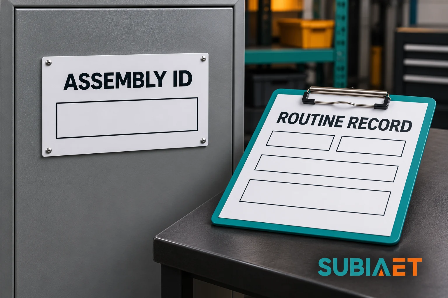
The historical ABB Technical Application Paper No. 11 distinguishes nameplate serial identity from the routine report model that includes order number, type designation, assembly identification number, inspection and test checks with results, and verifier fields. Your contract may specify the format. Request traceable evidence for every delivered assembly or applicable transportable unit, linked to the design revision and carrying the actual results and sign-off. Several units can appear in one package if their identities and applicable results can be distinguished.
The routine report records whether the as-built assembly met the defined acceptance criteria. It shows which checks were performed, identifies exceptions and their resolution, and provides traceability to the delivered assembly. When a test parameter is relevant to acceptance, record it or reference the agreed method, using the applicable verification requirements. Operating instructions and safety procedures are separate documents.
Component certificates, assembly design reports, routine verification records and factory acceptance tests address different objects and serve different purposes. A circuit breaker or enclosure certificate supports the claims it identifies within its stated scope and edition. The assembly design evidence addresses whether the arrangement incorporating those components meets the applicable assembly characteristics. The routine verification record shows what was checked on the manufactured unit and the results. Factory acceptance testing can witness or incorporate selected activities, confirm functions if specified, and provide a contract hold point.
The FAT may witness routine construction checks and performance tests if the contract so specifies. When FAT incorporates routine activities, the combined package still needs to identify the delivered assembly, reference the applicable design and drawing revision, record the checks and results, document exceptions and closeout, and carry the appropriate sign-off. A signed FAT witness sheet records the activities and equipment it identifies. Hunter Water’s STS 500 specification separately calls for routine verification documentation under its Australian/New Zealand requirements and a contractual FAT with representative involvement and automation checks where applicable. Agree how a combined package will document both sets of applicable evidence.
A builder might present a component certificate, a design family declaration or a sample routine form as evidence. Check what the certificate or declaration identifies and how it maps to the offered revision. If a design family declaration names a system but leaves the offered arrangement unlinked, ask for the evidence or controlled mapping that establishes coverage. A blank routine form shows what will be checked. Before release, obtain the applicable design coverage, a completed as-built routine record tied to the delivered assembly identifier, and any contractually required FAT evidence.
Factory acceptance and marking can support the documentation trail. If the offered arrangement is outside the design evidence, passing the routine checks and signing the FAT leave the design gap open. Apply the appropriate design verification to that characteristic and keep the as-built routine evidence separately identifiable, even when both activities are documented in one package.
Third-party witnessing and access to full proprietary design reports depend on the project and applicable jurisdiction. Some projects specify independent verification or certification. Others rely on the manufacturer’s documentation and the buyer’s right to review relevant evidence. Check any local conformity assessment requirements and agree the level of review, evidence access, format and third-party involvement in the contract. Ask what each declaration or witness record covers and how it relates to the supplied configuration.
A factory is buying one indoor low-voltage power switchgear and controlgear assembly for its main distribution room. Bid A follows its documented reference arrangement. Bid B offers an alternate incomer and revised cable entry. Both quote the same headline ratings.
| Check | Bid A | Bid B | Buyer action |
|---|---|---|---|
| Assembly and drawing identity | Offered arrangement and drawing revision trace to the stated design family. | The general certificate names a system family but does not identify the offered revision. | Ask both builders for the offered drawing, ratings and a coverage schedule by design characteristic. |
| Temperature-rise coverage | The coverage schedule identifies the offered loaded arrangement and applicable operating assumptions. | The alternate incomer and connection arrangement are absent from the thermal evidence supplied. | Hold the affected variant until the builder identifies the applicable verification route and supporting evidence. |
| Short-circuit coverage | The design record identifies the supported busbar and protective-device arrangement. | The alternate incomer has a component breaking rating, with no matching assembly evidence supplied. | Require assembly evidence for the offered arrangement and any conditions of the applicable verification route. |
| Enclosure and cable entry | The offered entry arrangement is listed in the enclosure evidence. | The revised cable entry is not identified in the supplied evidence. | Check that the final entry details are within the enclosure evidence or obtain verification of the affected characteristic. |
| Routine verification and FAT | The planned routine record can be matched to the assembly ID. A signed as-built record is still due. | The completed routine record submitted for release carries a different assembly ID. The FAT witness sheet is signed. | Obtain the correct as-built routine record, tie witness evidence to the delivered assembly and close exceptions. |
| Release decision | Eligible to progress with the verified arrangement, subject to as-built and contract closeout. | Affected manufacture or shipment remains on hold at the relevant milestone until the evidence gaps are closed. | Release only after applicable design coverage, matching routine records and agreed contract acceptance are in the file. |
Bid A provides design coverage that matches the offered drawing, ratings and loaded arrangement. The routine record is planned and will be tied to the assembly identifier. The buyer can proceed with Bid A, subject to receiving the signed as-built routine report before shipment and closing any contractual acceptance items.
Bid B quotes the same headline ratings but offers an alternate incomer and revised cable entry. The general certificate does not identify the offered revision. The alternate incomer and connection arrangement are absent from the thermal evidence. The short-circuit coverage does not address the offered busbar and protective-device arrangement. The revised cable entry is not in the supplied enclosure evidence. The completed routine record submitted for release carries a different assembly ID, and although the FAT witness sheet is signed, the FAT does not replace the missing as-built routine record for the delivered unit.
A routine pass does not resolve a design-evidence gap. If the arrangement is outside existing coverage, apply the appropriate verification route to the affected characteristics. An unrelated assembly ID leaves shipment on hold because the buyer cannot tie the routine evidence to the delivered unit. A signed FAT witness sheet records the activities and unit it identifies. Check the full package for traceable routine results as well as the agreed witness scope.
The buyer holds Bid B at the relevant milestone until the builder provides applicable design coverage, matches the routine evidence to the delivered assembly and closes any exceptions. If the builder demonstrates that the alternate incomer and revised entry are within a verified variant, supplies a correct as-built record for the delivered unit, and meets the FAT requirements, Bid B can progress. An identifier mismatch needs a documented resolution. If evidence for the actual unit is missing, obtain the applicable verification for that unit.
The case shows how evidence affects procurement at successive milestones. A conformity conclusion depends on the applicable edition, the verification routes and their conditions, and the actual assembly.
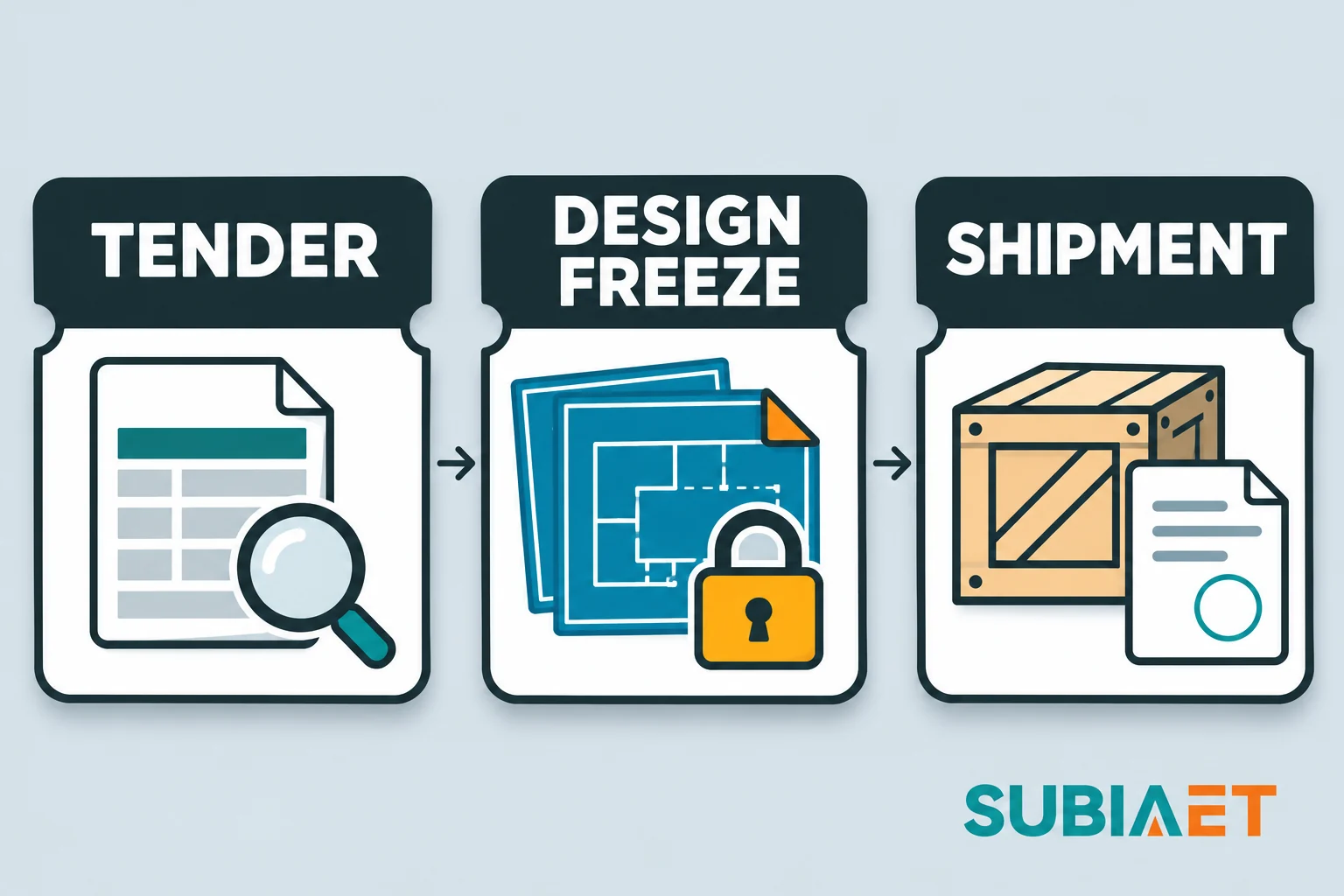
Request evidence at three distinct stages: tender comparison, design approval before affected manufacture and release before shipment.
Request the offered drawing, headline ratings, a coverage schedule by design characteristic, the design family and issue, and the identification of the applicable IEC 61439 parts and edition. The coverage schedule should map each characteristic to the verification route, reference the supporting reports or certificates, and state any limitations or conditions. This allows you to compare bids on an equal basis and identify any gaps before award.
Ask how the builder will handle changes during manufacture, who owns verification for substitutions, and what drawing and BOM revision control will apply. Clarify the routine verification format, the assembly or transport-unit identifier that will tie the record to the delivered unit, and the FAT scope if applicable. Agree on confidential evidence access and the level of detail you will receive.
Require that any proposed design change, device substitution or entry revision be submitted as an RFI before affected work proceeds. The RFI should describe the proposed change, identify the affected characteristics, state the proposed verification route and provide the applicable evidence or a schedule for obtaining it. Review the RFI, confirm the list of affected characteristics is complete, verify that the proposed route is applicable and that the conditions are met, and approve or reject the substitution.
Update the applicable drawing and bill-of-materials revision and obtain evidence sign-off that confirms which verified arrangement covers the change or which additional verification closes the gap. Agree a hold point for affected manufacture in the project’s approval plan.
Require the completed as-built routine verification record, tied to the assembly or transport-unit identifier, referencing the applicable drawing revision, recording the inspection and test results, documenting any exceptions and their corrective action, and carrying date and sign-off. Obtain the contractually required FAT evidence, tied to the delivered assembly, and close any open items.
Before authorizing shipment, confirm that the assembly identifier matches the routine record, the applicable design coverage is in the file, and the contract acceptance criteria are met. Agree the separate scope of site commissioning, final connection and system integration checks for the installed equipment.
Include the following in your technical specification and terms:
The assembly manufacturer shall provide design verification evidence for the offered arrangement under the applicable IEC 61439 product part and edition. Identify the design family, issue, general arrangement, ratings, loaded arrangement and service assumptions. Map each characteristic to the verification route, supporting evidence and limitations. Before affected work proceeds, submit any proposed design change or device substitution with the updated drawing and bill of materials, affected characteristics and applicable evidence. Perform routine verification on each manufactured assembly or applicable transportable unit and provide a completed record tied to the delivered assembly identifier. Reference the drawing revision, record the criteria and results, document exceptions and their resolution, and include date and sign-off. For specified FAT activities, record the agreed witness or functional scope, results and closeout for the identified equipment. If one package documents routine verification and FAT, identify the applicable checks and their results in that package.
Adjust the wording to match your project requirements and legal framework. The principle remains: design evidence that covers the offered configuration, approved changes before affected manufacture, and a traceable as-built routine record before shipment.
For further context on low-voltage switchgear families, review the overview of electrical switchgear functions and boundaries. The substation FAT and transformer evidence guide addresses factory acceptance for a packaged substation. LV switchboard internal separation explains how access and terminal protection are separate specification decisions. Transformer room and substation ventilation covers site room ventilation, which is distinct from assembly temperature-rise verification.
First check whether the substitute is already covered by a verified option and what approvals the contract requires. For an uncovered breaker change, identify each affected characteristic. A permitted thermal comparison may depend on the physical arrangement, power loss and terminal temperature rise. Fault and enclosure coverage need their own review where affected. Ask the builder to identify who owns verification of the changed design and to provide evidence for the actual revised configuration. Hold affected work or shipment at the agreed milestone until the evidence and approval are in place.
Check the mark or listing against its stated scope. It may refer to a component, a design family or a particular product and rating. For the actual purchase, match the applicable assembly design verification to the offered configuration, and tie the completed routine verification record to the unit that ships. Ask the supplier what each declaration or mark covers and how it relates to those two records.
Agree on a middle ground that protects the manufacturer’s intellectual property while giving you the information needed to confirm coverage. Request a coverage schedule that maps each characteristic to the verification route, identifies the supporting report by reference number and date, and states any limitations, without requiring full handover of the proprietary design database. Negotiate access to relevant excerpts or summaries that show the applicable ratings, arrangements and conditions, redacting any manufacturing details or proprietary calculations the manufacturer wishes to protect. You may also agree on third-party review, where an independent engineer reviews the full design evidence under a confidentiality agreement and confirms to you that the offered configuration is within the verified envelope. The key is to obtain enough information to make an informed decision without demanding unrestricted access to the manufacturer’s entire design library. Clarify the evidence format and access provisions in the contract before award, and treat confidentiality as a negotiation point rather than a reason to proceed without confirmation.
Use the verification route allowed for the characteristic and edition. The BEAMA guide’s UK-adoption table lists examples where design verification uses testing, reference comparison or assessment, with different choices for different characteristics. Ask for the method, scope and supporting evidence for the actual assembly. Where a test is needed, confirm that the test arrangement or permitted representative sample covers the configuration offered.
Ask for a controlled mapping from the assembly and transport-section identifiers to the drawing revision and applicable verification results. One record package can cover the lineup when it distinguishes the individual sections and the applicable checks. Hold shipment if the mapping is unresolved. If a record belongs to another assembly, obtain the correct record or have the responsible manufacturer complete and document the applicable verification for the actual assembly.
