Request a Quote
Share the equipment and project requirements. If you need help selecting a model, describe the application.
Have drawings or specifications? Email [email protected] with your project reference.


A transformer is rated in kVA because its electrical duty depends on the voltage and current it must carry. The voltage rating reflects the winding design, insulation and intended frequency. The current rating reflects heating under specified conditions. Apparent power accounts for the full RMS load current, including current associated with reactive power.
For example, an 80 kW load at a power factor of 0.80 needs 100 kVA. The longer answer is what the rest of this article covers: what each of the three quantities measures, where the rating comes from physically, what changes when power factor falls at a fixed real power, and where a single hand calculation has to give way to real project sizing.
The rating conditions are the starting point throughout. A rating only means something together with the voltage, frequency, temperature rise, cooling and ambient conditions it was established under. Changes to those conditions can affect the usable rating.
Real power, written in kW, is the rate at which energy is actually transferred and converted at the point you are measuring. For a motor, the measured electrical input supplies both shaft power and internal losses. Check whether the kW in a load list is input or output before using it to calculate demand. In a single AC circuit it is the average of the instantaneous voltage-times-current product over a cycle.
For a single-phase circuit, apparent power in kVA is the product of RMS voltage and RMS current at that same point, divided by 1,000. The three-phase formula also accounts for the phase arrangement. It does not ask what the load does with the energy. It only asks how much voltage and how much current are present.
Power factor is the ratio between the two:
PF = P / S = kW / kVA
Three conditions matter for that ratio to be meaningful. Use consistent RMS quantities and the real power measured at the same point in the circuit and over the same interval. When the voltage and current are sinusoidal, the same relationship can be drawn as a right triangle, and the power factor equals the cosine of the phase angle between them. Schneider Electric’s power triangle explanation
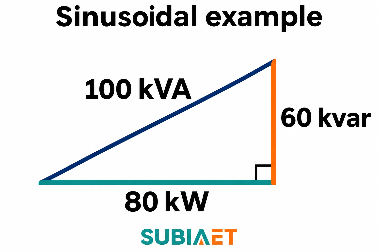
Take a load drawing 80 kW of real power with a lagging power factor of 0.80. From PF = P/S, the apparent power is 80 / 0.80 = 100 kVA. The reactive component follows from the triangle:
Q = √(S² − P²) = √(100² − 80²) = √(10,000 − 6,400) = √3,600 = 60 kvar
So the example is a triangle with 80 kW along the horizontal, 60 kvar vertically and 100 kVA on the hypotenuse. The lagging direction means the current reaches its peak after the voltage does, as in a sinusoidal inductive load.
Two traps sit in that triangle. The first is arithmetic: 80 kW and 60 kvar do not add up to 140 of anything. They are perpendicular components, which is exactly why the hypotenuse is smaller than their sum. Adding them directly overstates the apparent power in this example.
The second trap is conceptual: 0.80 power factor is not 80% efficiency. Efficiency compares real power out with real power in — both in kW — and accounts for losses as heat. Power factor compares real power with apparent power at a single point and says nothing about how much energy the transformer itself wastes. In a hypothetical case, a transformer can be 98% efficient while the connected load has a power factor of 0.80, because the numbers describe different things.
Reactive power in an inductive load represents energy exchanged between the source and the load’s magnetic field. The reactive component contributes to the RMS current flowing through the supplying conductors and windings. That RMS current produces I²R loss in the winding resistance.
The rating pairs a voltage and a current on a specified side of the transformer. Use RMS quantities for the calculation.
For a single-phase circuit:
S (kVA) = V × I / 1,000, with V in volts and I in amperes
For a balanced three-phase rating:
S (kVA) = √3 × V_LL × I_L / 1,000, with V_LL the line-to-line RMS voltage in volts and I_L the RMS line current in amperes
The same formula run in reverse gives the rated current on either side: divide the volt-amperes by the rated voltage on the side you are checking. For balanced three-phase equipment, use that side’s rated line-to-line voltage and also divide by √3. That is why a 100 kVA transformer has a small current on the high-voltage side and a large one on the low-voltage side with the same rated kVA at a different voltage. For example, a hypothetical 100 kVA, 11 kV to 400 V three-phase transformer has a rated line current of about 5.25 A on the 11 kV side and 144.34 A on the 400 V side. Schneider Electric’s rated-current formulas
Two loss mechanisms help explain why operating voltage and current both matter.

Core loss exists whenever the transformer is energised, even with no load connected. In a laminated steel core, it comes from the alternating flux in the steel laminations — hysteresis as the magnetic domains reverse each cycle, and eddy currents circulating in the sheet steel. Its magnitude depends on the operating voltage, the frequency and the core design: the grade and thickness of the lamination steel, the flux density it is run at, and how the sheets are stacked and insulated.
Winding resistance loss appears as current flows. At a fixed resistance it is proportional to the square of the current — double the current and you quadruple that loss term. Real windings add eddy and stray loss components that are not strictly I²R, so estimating load loss purely from current is an approximation rather than an exact result. Actual operating temperature also depends on cooling and service conditions. Eaton’s current-based load-loss estimate
The key point is that at a fixed voltage and phase arrangement, a given kVA corresponds to a given line-current magnitude. A winding rated for 144 A does not get to carry more current because the load happens to be unity power factor. It carries what the load draws, and heats accordingly.
Temperature rise is one consideration in the kVA rating. Read the nameplate with the equipment’s specified voltage, frequency, cooling, ambient and duty conditions. A transformer in a hot, poorly ventilated room, or one running at altitude where air is thinner, is not operating under the same conditions as the one the rating describes. Eaton’s medium-voltage transformer fundamentals
One honest qualification belongs here. It would be too strong to say that transformer losses are entirely independent of power factor. The dominant reason for the kVA rating is that the current magnitude is set by apparent power, and the resistance loss follows that current. The total loss also depends on the transformer’s design and the actual current waveform. Harmonic currents can change the thermal duty even when the RMS current looks acceptable.
The same kVA basis can describe the electrical duty for different mixes of motors, rectifiers and resistive heaters. For a specific installation, use the expected load profile and the manufacturer’s rating conditions to confirm what the transformer can serve.
The cleanest way to see why the distinction matters is to hold real power and voltage fixed and let power factor move.
Assume a sinusoidal, balanced load at a fixed 400 V line-to-line RMS, drawing a fixed 80 kW of real electrical power at the measurement point. Keep all readings on the same side for the comparison.
At PF 1.00: S = 80 / 1.00 = 80 kVA. The line current is 80,000 / (√3 × 400) = 80,000 / 692.8 = 115.47 A.
At PF 0.80 lagging: S = 80 / 0.80 = 100 kVA. The line current is 100,000 / (√3 × 400) = 144.34 A.
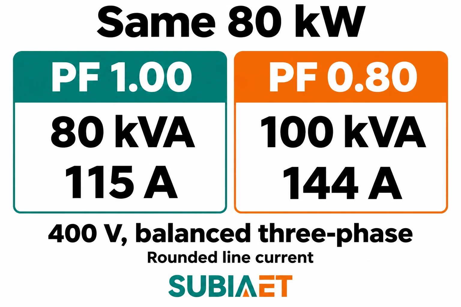
The current rose by 144.34 / 115.47 = 1.25, or 25% before rounding, at exactly the same 80 kW of useful power. In the example, real power stays the same as the power factor changes.
The percentage change in resistance loss is larger than the change in current. Resistance loss in the winding scales with the square of the current, so at a fixed resistance the loss term rises by 1.25² ≈ 1.56 — roughly 56% more. That is the mechanism behind the whole rating convention in one line: the same electrical input kW can increase the winding resistance loss when the load draws more current at a lower power factor.
Read the rating backwards and the same arithmetic explains what kVA means as a capacity. At 100 kVA the calculation gives 100 kW at unity power factor and 80 kW at a power factor of 0.80. Both cases have the same current at the same voltage in this calculation. Confirm actual equipment suitability using its specified conditions.
The 100 kVA result describes the assumed 80 kW load at a power factor of 0.80. It ignores load diversity, future growth, harmonic content, ambient temperature, altitude, cooling arrangement, motor starting duty and the difference between coincident peak demand and installed capacity. A real selection has to account for all of those, and a transformer that is generously sized for the arithmetic may still be wrong for the installation for reasons other than apparent power. Compare the loss data and service conditions for the actual candidates.
A nameplate rating describes equipment capability under stated conditions. Demand is the electrical duty the loads draw together. It can rise in the morning, peaks when the largest loads coincide, drops at night and varies with production schedule, season and weather.
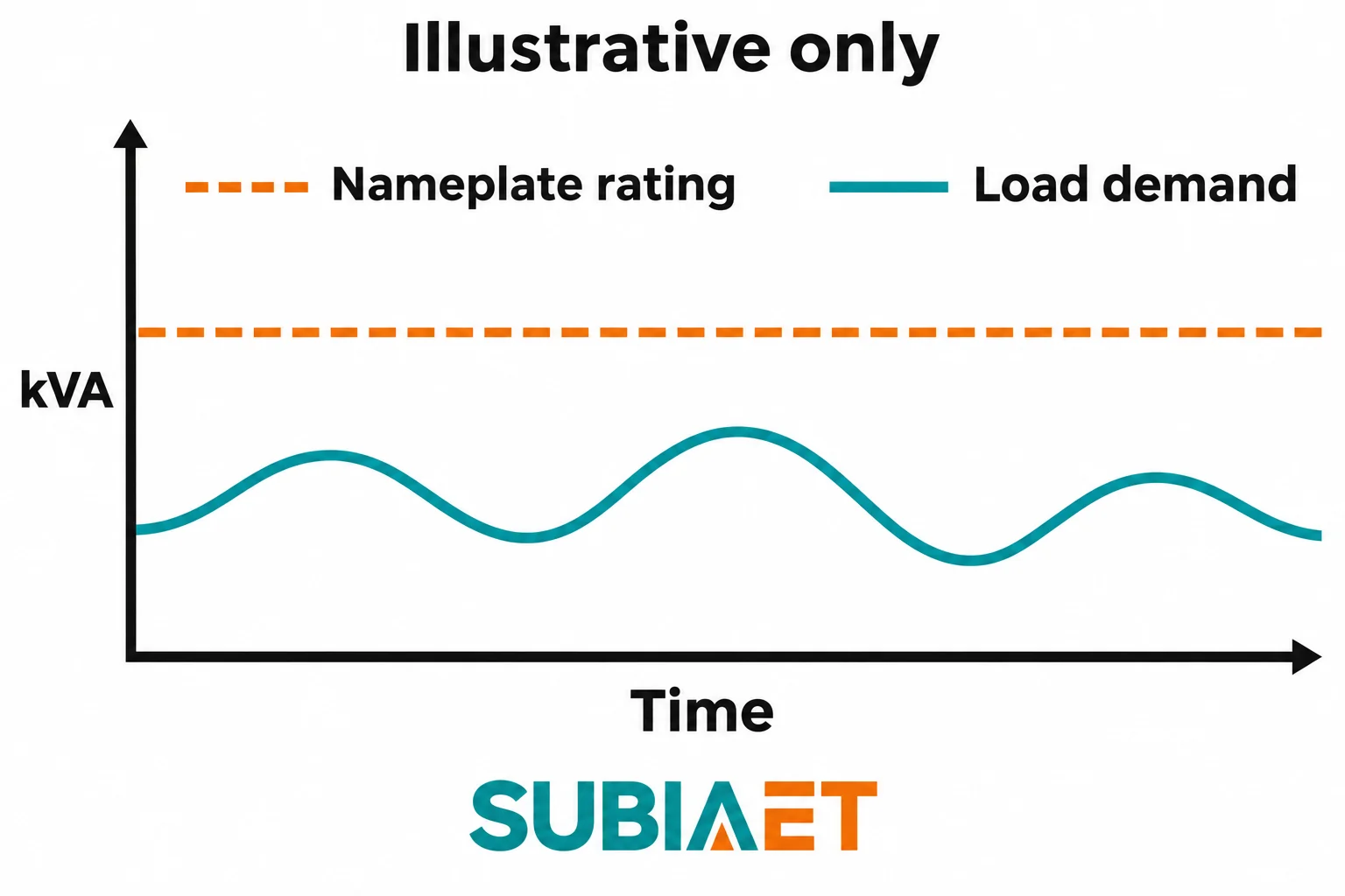
The comparison that matters is between the transformer’s rated apparent power and the coincident apparent power demand at the same point, measured over an interval that captures the real peak. Separate loads can reach their maximum demand at different times. Alongside that, look at the per-phase RMS current. Current is what heats the winding, and current is what the rating formula was built from.
Imbalance. The formula √3 × V_LL × I_L assumes a balanced load. When phases are unevenly loaded, the average or a single line current can look acceptable while one phase runs above its share. Winding heating is local, so the individual phase currents deserve inspection rather than a single averaged figure.
Distortion. With non-linear loads the current waveform is no longer sinusoidal, and the power triangle stops being a complete description. True power factor uses active and apparent power with RMS quantities taken over the full waveform; displacement factor uses only the fundamental component. The two can diverge significantly — a load with a displacement factor near unity can still have a much lower true power factor once harmonic current is included. For rating comparisons, true power factor is the relevant figure, and the thermal implications for the transformer under distorted current need to be verified using the actual waveform. Schneider Electric’s guide to true and displacement power factor
Starting duty. Motor starting currents, energisation inrush and similar short-duration events are a separate check from the continuous kVA rating. Motor starting can cause voltage drop and transformer inrush can affect protection operation. The magnitude and duration of each event matter. Treating a starting current as if it were a continuous demand, or ignoring it entirely, both misrepresent the situation.
For a project where these factors genuinely matter — a plant expansion adding a large motor group, or a distribution board feeding drive-heavy equipment — the working method is to build the demand case first, then compare candidate ratings against it under the actual ambient and cooling conditions. That process is set out in more detail in the guide to transformer sizing for a factory expansion, which takes the question from load inventory through to a rated capacity. The 400 V example above is deliberately too short to serve as that calculation; it isolates one variable so the ratio between kW, kVA and current is visible.
If you are preparing an enquiry or reviewing a nameplate, three figures should travel together: the real power the load actually consumes, the power factor it presents, and the resulting apparent power and current at the point of connection. Supplying only one of them leaves the other two to be guessed, so record any assumed values as assumptions. For the 400 V example, record 80 kW electrical input, PF 0.80 lagging, 100 kVA and 144.34 A per line at the same measurement point. Log a different operating interval separately if the load mix and power factor change.
The transformer family pages give the structure of the range if you are matching a rating to an application: oil-immersed transformers for the conventional distribution role, dry-type transformers where the installation favours a dry insulation system, and the full transformers index for the rest of the series. To place the rating question in a wider context, what an electrical transformer is and how it works covers the induction principle behind the windings, and the role of a distribution transformer in the power system explains where the equipment sits between the network and the load.
The kVA rating describes voltage and current capability under stated conditions. For the same kW, a load with lower power factor draws more current at the same voltage. Winding heating is one reason that current matters.
Yes. At unity power factor, kW and kVA have the same numerical value at the measurement point. A resistive load with sinusoidal supply is one example.
Use kVA alongside the voltage, phase and frequency, then compare the expected demand, starting conditions, harmonics and site cooling with the selected design.
Power factor is real power divided by apparent power at one point. Efficiency compares real output power with real input power. Both use ratios, with different quantities in their denominators.
At fixed real power and voltage in a balanced system, current increases as power factor falls. In the 400 V example, a drop from 1.00 to 0.80 raises the current from about 115 A to about 144 A.
